Content .. 1455 1456 1457 1458 ..
Nissan Qashqai (2007-2010). Manual - part 1457
DEF-4
< FUNCTION DIAGNOSIS >
REAR WINDOW DEFOGGER SYSTEM
FUNCTION DIAGNOSIS
REAR WINDOW DEFOGGER SYSTEM
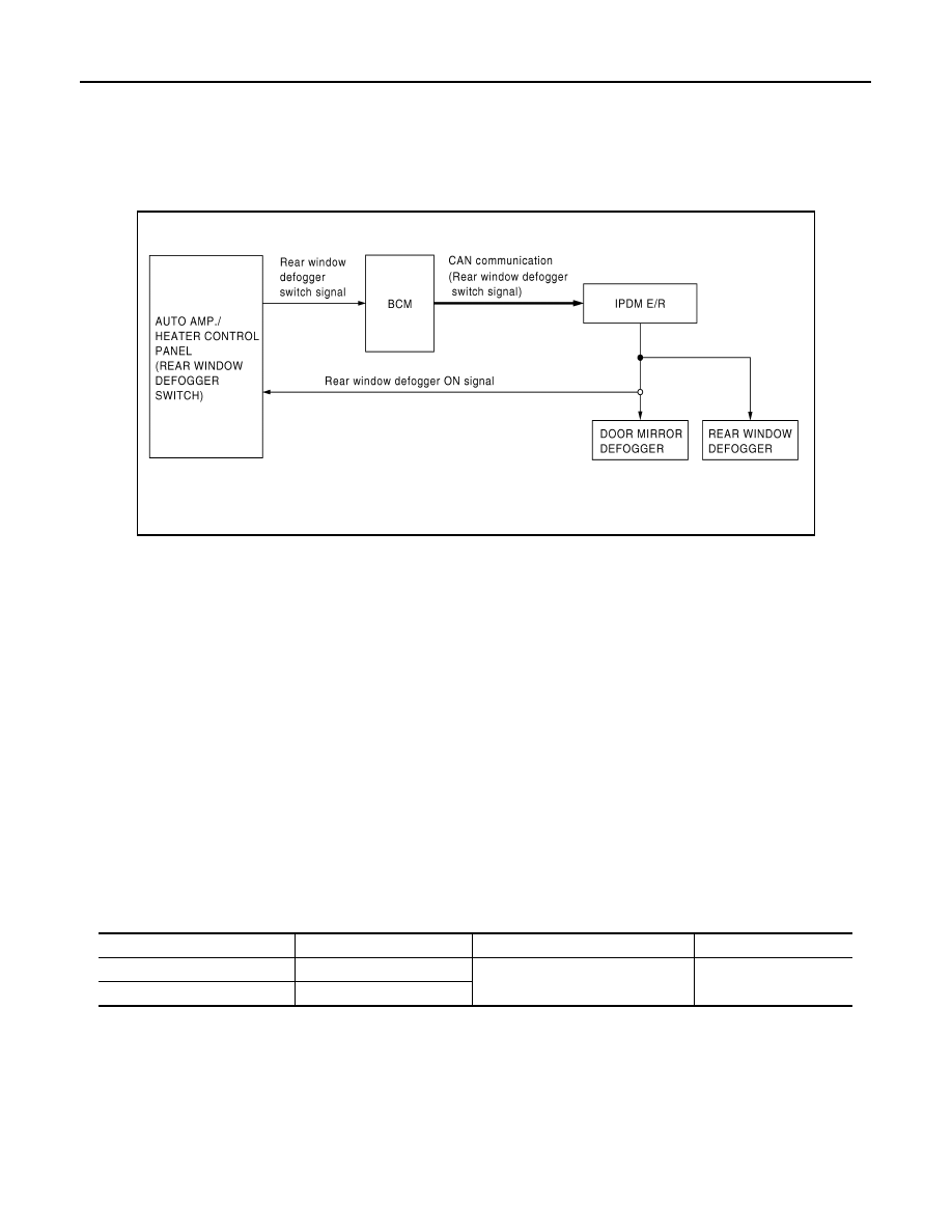
System Diagram
INFOID:0000000000951258
System Description
INFOID:0000000000951259
OPERATION DESCRIPTION
• BCM detects that the rear window defogger switch is turned ON when the ignition switch is ON, and then
transmits the rear window defogger switch signal to IPDM E/R via CAN communication for approximately 15
minutes.
• IPDM E/R turns rear window defogger relay ON when it receives the rear window defogger switch signal.
Then, it transmits the rear window defogger ON signal to ECM via CAN communication.
• The power is supplied to the rear window defogger and door mirror defogger (with mirror defogger) when the
rear window defogger relay is turned ON.
TIMER FUNCTION
• BCM transmits the rear window defogger switch signal to IPDM E/R for approximately 15 minutes when the
rear window defogger switch is turned ON with the ignition switch ON. Then, IPDM E/R operates the rear
window defogger and door mirror defogger (with mirror defogger).
• The timer is cancelled if the rear window defogger switch is pressed again during timer operation. BCM
stops the output of rear window defogger switch signal. The same reaction also occurs during timer opera-
tion if the ignition switch is turned OFF.
INPUT/OUTPUT SIGNAL CHART
*: With mirror defogger
Component Parts Location
INFOID:0000000000951260
JMLIA0030GB
Switch
Input signal to BCM
BCM function
Acutuator
Rear window defogger switch
Defogger switch signal
Rear window defogger & Door mir-
ror defogger
*
control
Rear window defogger
Door mirror defogger
*
Ignition switch
Ignition signal