Nissan Qashqai (2007-2010). Manual - part 31
 

  Index      Nissan     Nissan Qashqai - service and repair manual 2007 - 2010 year


Search            copyright infringement  


Content   ..  29  30  31  32   ..


Nissan Qashqai (2007-2010). Manual - part 31


EM-72

< ON-VEHICLE REPAIR >

[HR16DE]

OIL SEAL

REMOVAL

1.

Remove the following parts:
• Front fender protector (RH): Refer to 

EXT-21, "Exploded View"

.

• Drive belt: Refer to 

EM-16, "Removal and Installation"

.

• Crankshaft pulley: Refer to 

EM-46, "Exploded View"

.

2.

Remove front oil seal using a suitable tool.

CAUTION:

Be careful not to damage front timing chain case and crankshaft.

INSTALLATION

1.

Apply new engine oil to both oil seal lip and dust seal lip of new front oil seal.

2.

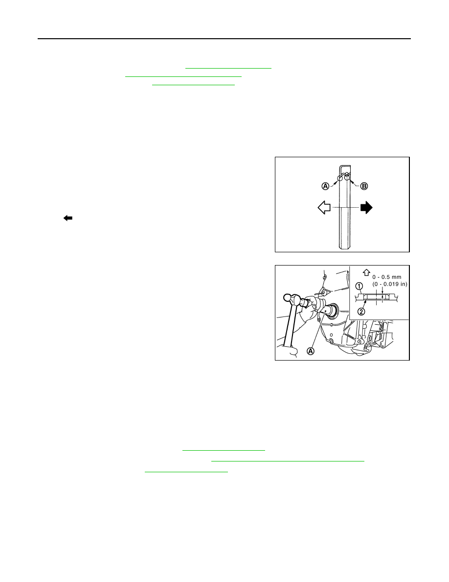
Install front oil seal.
• Install front oil seal so that each seal lip is oriented as shown in

the figure.

• Using a suitable drift, press-fit until the height of front oil seal

(2) is level with the mounting surface.

- Suitable drift (A): outer diameter 50 mm (1.97 in), inner diame-

ter 44 mm (1.73 in).

• Make sure the garter spring is in position and seal lips not

inverted

CAUTION:

• Be careful not to damage front timing chain case and

crankshaft.

• Press-fit straight and avoid causing burrs or tilting oil seal.

3.

Install in the reverse order of removal, for the rest of parts.

REAR OIL SEAL

REAR OIL SEAL : Removal and Installation

INFOID:0000000000893867

REMOVAL

1.

Remove transaxle assembly. Refer to 

TM-23, "Exploded View"

.

2.

Remove clutch cover and clutch disk. Refer to 

CL-16, "HR16DE, MR20DE : Exploded View"

3.

Remove flywheel. Refer to 

EM-93, "Exploded View"

.

4.

Remove rear oil seal with a suitable tool.

CAUTION:

Be careful not to damage crankshaft and cylinder block.

INSTALLATION

1.

Apply the liquid gasket lightly to entire outside area of new rear oil seal.
Use Genuine Liquid Gasket or equivalent.

A

: Dust seal lip

B

:  Oil  seal  lip

: Engine outside

: Engine inside

PBIC3485J

1

: Front cover

: Engine outside

PBIC3729E

OIL SEAL

EM-73

< ON-VEHICLE REPAIR >

[HR16DE]

C

D

E

F

G

H

I

J

K

L

M

A

EM

N

P

O

2.

Install rear oil seal so that each seal lip is oriented as shown in
the figure.

• Press-fit rear oil seal with a drift outer diameter 113 mm (4.45

in) and inner diameter 90 mm (3.54 in) (commercial service
tool) (A).

CAUTION:

• Be careful not to damage crankshaft and cylinder block.
• Press-fit oil seal straight to avoid causing burrs or tilt-

ing.

• Never touch grease applied onto oil seal lip.

• Press in rear oil seal (1) to the position as shown in the figure.

3.

After press-fitting rear oil seal, completely wipe off any liquid gasket protruding to rear end surface side.

4.

Install in the reverse order of removal, for the rest of parts. 

A

: Dust seal lip

B

:  Oil  seal  lip

: Engine outside

: Engine inside

PBIC3485J

PBIC3660E

A

: Rear end surface of cylinder block

PBIC3761E

EM-74

< ON-VEHICLE REPAIR >

[HR16DE]

CYLINDER HEAD

CYLINDER HEAD

Exploded View

INFOID:0000000000943691

REMOVAL

DISASSEMBLY

1.

Cylinder head assembly 

2.

Cylinder head bolt

3.

Washer

4.

Cylinder head gasket

A.

Refer to 

EM-75

Refer to 

GI-4, "Components"

 for symbols in the figure.

PBIC3731E

PBIC3734E

CYLINDER HEAD

EM-75

< ON-VEHICLE REPAIR >

[HR16DE]

C

D

E

F

G

H

I

J

K

L

M

A

EM

N

P

O

Removal and Installation

INFOID:0000000000894029

REMOVAL

1.

Release fuel pressure. Refer to 

EC-357, "Inspection"

.

2.

Drain engine coolant and engine oil. Refer to 

CO-9, "Draining"

 and 

LU-7, "Draining"

.

CAUTION:

• Perform this step when the engine is cold.
• Never spill engine coolant and engine oil on drive belt.

3.

Remove the following components and related parts.
• Front fender protector (RH): Refer to 

EXT-21, "Exploded View"

.

• Alternator: Refer to 

CHG-25, "HR16DE MODELS : Exploded View"

.

• Exhaust front tube: Refer to 

EX-5, "Exploded View"

.

• Exhaust manifold: Refer to 

EM-32, "Exploded View"

.

• Intake manifold: Refer to 

EM-29, "Exploded View"

.

• Fuel tube and fuel injector: Refer to 

EM-35, "Exploded View"

.

• Water outlet: Refer to 

CO-21, "Exploded View"

.

• Drive belt: Refer to 

EM-16, "Removal and Installation"

.

• Front cover: Refer to 

EM-46, "Exploded View"

.

• Camshaft: Refer to 

EM-55, "Exploded View"

.

4.

Remove cylinder head loosening bolts in reverse order as
shown in the figure with cylinder head wrench (commercial ser-
vice tool). 

5.

Remove cylinder head gasket.

INSTALLATION

1.

Install new cylinder head gasket.

2.

Tighten cylinder head bolts in numerical order as shown in the
figure with the following procedure to install cylinder head.

CAUTION:

If cylinder head bolts are re-used, check their outer diame-
ters before installation. Refer to “Cylinder Head Bolts Outer
Diameter”.

a.

Apply new engine oil to threads and seating surfaces of mount-
ing bolts.

b.

Tighten all bolts.

1.

Spark plug

2.

Valve collet

3.

Valve spring retainer

4.

Valve spring

5.

Valve spring seat

6.

Valve oil seal

7.

Valve guide (EXH)

8.

Valve guide (INT)

9.

Cylinder head

10. Valve seat (EXH)

11.

Valve (EXH)

12. Valve seat (INT)

13. Valve 

(INT)

A.

Refer to 

EM-76

B.

Refer to 

EM-76

Refer to 

GI-4, "Components"

 for symbols in the figure.

A

: EXH side

B

: INT side

: Engine front

PBIC3732E

A

: EXH side

B

: INT side

: Engine front

PBIC3732E


Content   ..  29  30  31  32   ..