Nissan Qashqai (2007-2010). Manual - part 30
 

  Index      Nissan     Nissan Qashqai - service and repair manual 2007 - 2010 year


Search            copyright infringement  


Content   ..  28  29  30  31   ..


Nissan Qashqai (2007-2010). Manual - part 30


EM-68

< ON-VEHICLE REPAIR >

[HR16DE]

CAMSHAFT

2.

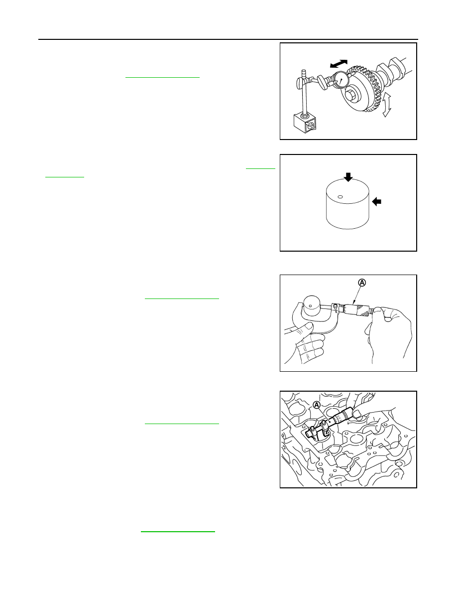
Measure the camshaft sprocket runout with a dial indicator.
(Total indicator reading)

• If it exceeds the limit, replace camshaft sprocket.

Valve Lifter 

Check if surface of valve lifter has any wear or cracks.
• If anything above is found, replace valve lifter. Refer to 

EM-116,

"Camshaft"

.

Valve Lifter Clearance

VALVE LIFTER OUTER DIAMETER
Measure the outer diameter of valve lifter with a micrometer (A).

VALVE LIFTER HOLE DIAMETER
Measure the diameter of valve lifter hole of cylinder head with an
inside micrometer (A).

VALVE LIFTER CLEARANCE
• (Valve lifter clearance) = (Valve lifter hole diameter) – (Valve lifter outer diameter)

• If out of the standard, referring to the each standard of valve lifter outer diameter and valve lifter hole diame-

ter, replace either or both valve lifter and cylinder head.

INSPECTION AFTER INSTALLATION

Limit:

Refer to 

EM-116, "Camshaft"

.

KBIA1493J

KBIA0182E

Standard:

Refer to 

EM-116, "Camshaft"

.

PBIC3185J

Standard:

Refer to 

EM-116, "Camshaft"

.

PBIC3184J

Standard:

Refer to 

EM-116, "Camshaft"

.

CAMSHAFT

EM-69

< ON-VEHICLE REPAIR >

[HR16DE]

C

D

E

F

G

H

I

J

K

L

M

A

EM

N

P

O

Inspection for Leaks

The following are procedures for checking fluids leak, lubricates leak.

• Before starting engine, check oil/fluid levels including engine coolant and engine oil. If less than required

quantity, fill to the specified level. Refer to 

MA-21, "Fluids and Lubricants"

.

• Use procedure below to check for fuel leakage.
- Turn ignition switch “ON” (with engine stopped). With fuel pressure applied to fuel piping, check for fuel leak-

age at connection points.

- Start engine. With engine speed increased, check again for fuel leakage at connection points.
• Run engine to check for unusual noise and vibration.

NOTE:
If hydraulic pressure inside timing chain tensioner drops after removal/installation, slack in the guide may
generate a pounding noise during and just after engine start. However, this is normal. Noise will stop after
hydraulic pressure rises.

• Warm up engine thoroughly to make sure there is no leakage of fuel, or any oil/fluids including engine oil and

engine coolant.

• Bleed air from lines and hoses of applicable lines, such as in cooling system.
• After cooling down engine, again check oil/fluid levels including engine oil and engine coolant. Refill to the

specified level, if necessary.

Summary of the inspection items:

*: Transmission/transaxle/CVT fluid, power steering fluid, brake fluid, etc.

Inspection of Camshaft Sprocket (INT) Oil Groove

CAUTION:

• Perform this inspection only when DTC P0011 is detected in self-diagnostic results of CONSULT-III

and it is directed according to inspection procedure of EC section. Refer to 

EC-87, "Diagnosis

Description"

.

• Check when engine is cold so as to prevent burns from the splashing engine oil.

1.

Check engine oil level. Refer to 

LU-6, "Inspection"

.

2.

Perform the following procedure so as to prevent the engine from being unintentionally started while
checking.

a.

Release the fuel pressure. Refer to 

EC-357, "Inspection"

.

b.

Remove intake manifold. Refer to 

EM-29, "Exploded View"

.

c.

Disconnect ignition coil and injector harness connectors. Refer to 

EM-43, "Exploded View"

.

3.

Remove intake valve timing control solenoid valve. Refer to 

EM-46, "Exploded View"

.

4.

Crank engine, and then make sure that engine oil comes out
from intake valve timing control solenoid valve hole (A). End
crank after checking.

WARNING:

Be careful not to touch rotating parts (drive belts, idler pul-
ley, and crankshaft pulley, etc.).

CAUTION:

• Prevent splashing by using a shop cloth so as to prevent

the worker from injury from engine oil and so as to prevent engine oil contamination.

• Prevent splashing by using a shop cloth so as to prevent engine oil from being splashed to

engine and vehicle. Especially, be careful not to apply engine oil to rubber parts of drive belts,
engine mounting insulator, etc. Wipe engine oil off immediately if it is splashed.

Items

Before starting engine

Engine running

After engine stopped

Engine coolant

Level

Leakage

Level

Engine oil

Level

Leakage

Level

Other oils and fluid*

Level

Leakage

Level

Fuel

Leakage

Leakage

Leakage

1

:  Plug

:Engine front

PBIC3706E

EM-70

< ON-VEHICLE REPAIR >

[HR16DE]

CAMSHAFT

5.

Perform the following inspection if engine oil does not come out from intake valve timing control solenoid
valve oil hole of the cylinder head.
• Remove oil filter, and then clean it. Refer to 

EM-65, "Inspection"

.

• Clean oil groove between oil strainer and intake valve timing control solenoid valve. Refer to 

LU-3,

"Engine Lubrication System"

 and 

LU-3, "Engine Lubrication System Schematic"

.

6.

Remove components between intake valve timing control solenoid valve and camshaft sprocket (INT),
and then check each oil groove for clogging.
• Clean oil groove if necessary. Refer to 

LU-3, "Engine Lubrication System"

 and 

LU-3, "Engine Lubrica-

tion System Schematic"

.

7.

After inspection, install removed parts in the reverse order.

OIL SEAL

EM-71

< ON-VEHICLE REPAIR >

[HR16DE]

C

D

E

F

G

H

I

J

K

L

M

A

EM

N

P

O

OIL SEAL

VALVE OIL SEAL

VALVE OIL SEAL : Removal and Installation

INFOID:0000000000893865

REMOVAL

1.

Remove camshafts. Refer to  

EM-55, "Exploded View"

.

2.

Remove valve lifters. Refer to  

EM-55, "Exploded View"

.

3.

Rotate crankshaft, and set piston whose valve oil seal is to be removed to TDC. This will prevent valve
from dropping into cylinder.

CAUTION:

When rotating crankshaft, be careful to avoid scarring front cover with timing chain.

4.

Remove valve collet. 
• Compress valve spring with the valve spring compressor, the

attachment and the adapter [SST: KV10116200] (A). Remove
valve collet with a magnet hand (B).

CAUTION:

Be careful not to damage valve lifter holes.

5.

Remove valve spring retainer, valve spring and valve spring seat. Refer to 

EM-74, "Exploded View"

.

6.

Remove valve oil seal with the valve oil seal puller [SST:
KV10107902] (A).

INSTALLATION

1.

Apply new engine oil to valve oil seal joint surface and seal lip.

2.

Press in valve oil seal to the height “H” shown in the figure with
the valve oil seal drift [SST: KV10115600] (A).

3.

Install in the reverse order of removal, for the rest of parts. 

FRONT OIL SEAL

FRONT OIL SEAL : Removal and Installation

INFOID:0000000000893866

PBIC3727E

PBIC3728E

Height “H”

: 13.2 - 13.8 mm (0.520 - 0.543 in)

PBIC3211J


Content   ..  28  29  30  31   ..