Lexus NX450H+ (2024 year). Manual in english - page 10
 

  Index      Manuals     Lexus NX450H+ (2024 year). Manual in english


Search            copyright infringement  


Content      ..     8      9      10      11     ..


Lexus NX450H+ (2024 year). Manual in english - page 10


If the temperature inside the vehicle is high, such as after the vehicle has been parked
in the sun

About connected external devices

Depending on the connected external device, charging may occasionally be suspended
and then start again. This is not a malfunction.

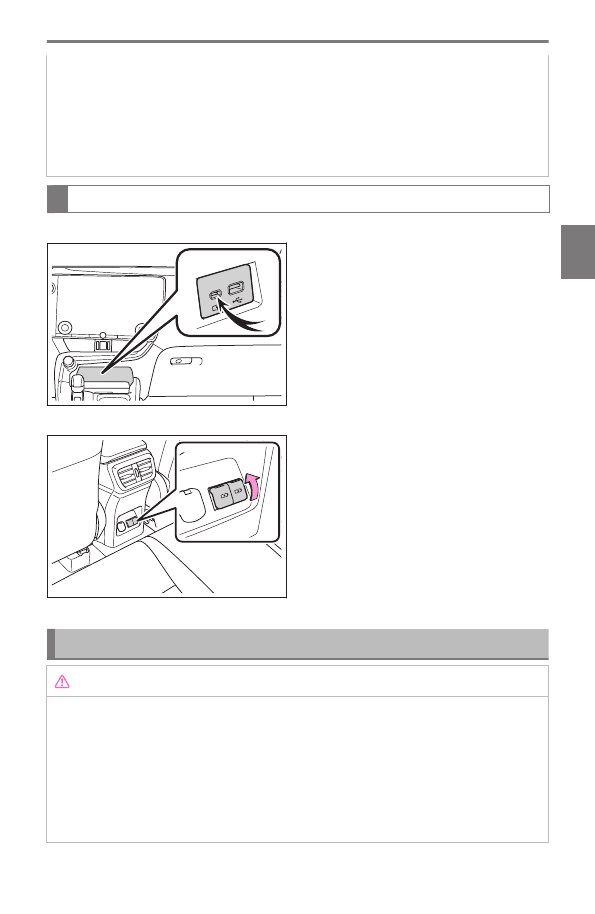
Use the USB charging port

▶ 

Instrument panel

▶ 

On the rear console

Open the lid.

Function and operation of the power outlet (12 VDC)

NOTICE

To prevent damage to the power outlet (12 VDC)

Do not insert foreign objects into the ports.

Do not spill water or other liquids into the ports.

When the power outlets (12 VDC) are not in use, close the lids. If a foreign object or
liquid enters a port may cause a short circuit.

Do not apply excessive force to or impact the power outlets (12 VDC) ports.

4-5. Using the interior features

311

4

Interior feat

ur

es

NOTICE

To prevent 12-volt battery discharge

Do not use the power outlets (12 VDC) for a long period of time with the hybrid system
stopped.

The power outlet can be used to supply power for devices which operate on 12
VDC at less than 10A (power consumption of 120 W).

When connecting multiple devices, make sure that the total power consumption of all the
connected devices is less than 120 W.

INFORMATION

The power outlet can be used when

The power switch is in ACC or ON.

When stopping the hybrid system

Disconnect electrical devices with charging functions, such as mobile battery packs.
If such devices are left connected, the hybrid system may not stop normally.

Using the accessory sockets (12 VDC)

▶ 

Instrument panel

Remove the cap.

▶ 

On the rear console

4-5. Using the interior features

312

Open the lid.

▶ 

In the luggage compartment

Open the lid.

Function and operation of the wireless charger

A portable device, such as a smartphone or mobile battery, can be charged by
just placing it on the charging area, provided the device is compatible with the Qi
wireless charging standard created by the Wireless Power Consortium.

WARNING

Caution while driving

When charging a portable device while driving, for safety reasons, the driver should not
operate the portable device.

Precautions for when driving

Do not charge small, lightweight portable devices, such as wireless earbuds, while driv-
ing. Lightweight devices may fly off of the charging tray, possibly leading to an accident.

Caution regarding interference with electronic devices

People with implantable cardiac pacemakers, cardiac resynchronization therapy pace-
makers or implantable cardioverter defibrillators, as well as any other electrical medical
device, should consult their physician about the usage of the wireless charger.
Operations of the wireless charger may have an affect on medical devices.

To prevent damage or burns

Observe the following precautions.
Failure to do so may result in the possibility of fire, equipment failure or damage, or burns
due to heat.

Do not put any metallic objects between the charging area and the portable device
while charging.

Do not attach metallic objects, such as aluminum stickers, to the charging area.

4-5. Using the interior features

313

4

Interior feat

ur

es

WARNING

Do not charge portable devices with aluminum stickers or other metallic objects
attached to the side which touches the charging area.

Do not store items on the wireless charger instead of in an auxiliary box.

Do not apply force or impact to the wireless charger.

Do not disassemble, modify or remove the wireless charger.

Do not attempt to charge portable devices which are not compatible with the Qi
wireless charging standard.

Do not allow magnetic objects to come near the wireless charge

Do not perform charging if the charging area is dirty

Do not cover the wireless charger with a cloth or other object while charging.

NOTICE

Preventing malfunction and corruption of data

Do not bring magnetic cards, such as credit cards, or magnetic recording media, etc.,
close to the charger while charging, otherwise, data may be erased.
Additionally, do not bring precision instruments such as wrist watches, close to the
wireless charger, as such objects may malfunction.

Do not perform charging with a contactless smart card, such as a credit card, between
the charging surface of a portable device and the charging area. The IC chip in the
card may become extremely hot, possibly damaging the portable device or smart
card.Failure to do so may result in the possibility of fire, equipment failure or damage,
or burns due to heat.
Be extra careful to not charge a portable device with a case or cover which a
contactless smart card can be inserted.

Do not leave portable devices in the vehicle. The temperature inside the vehicle may
become high, when in direct sunlight, possibly damaging the device.

To prevent 12-volt battery discharge

When the hybrid system is stopped, do not use the wireless charger for longer than
necessary.

INFORMATION

The wireless charger can be operated when

The power switch is in ACC or ON.

4-5. Using the interior features

314

About connected portable devices

Portable devices compatible with the Qi wireless charging standard can be charged
by the wireless charger. However, compatibility with all devices which meet the Qi
wireless charging standard is not guaranteed.

The wireless charger is designed to supply low power electricity (5 W or less) to a
cellular phone, smartphone, or other portable device.

Failure to do so may result in the possibility of fire,However, portable devices, such as
the following, can be charged with more than 5 W.

7.5 W charging compatible iPhones can be charged at 7.5 W or less.

Portable devices which conform to WPC Ver 1.2.4 (Extended Power profile) can be
charged at 10 W or less.

Using the smart access system with push-button start

Charging will be suspended for the smart access system with push-button start to detect
the electronic key during charging such as when the electronic key has been brought
outside the vehicle. When the electronic key is detected, charging will automatically start
again.

If a cover or accessory is attached to the portable device

Do not charge a portable device if a cover or accessory which is not Qi compatible is
attached.
Even if a device is “Qi” compatible, charging may not be possible if a cover or accessories
are attached. (

 P.317

Charging precautions

While charging, the wireless charger and the portable device will become warm. This is
not a malfunction.
If a portable device becomes warm while charging and charging stops due to the
protection function of the portable device, wait until the portable device cools down and
charge it again.
Also, to decrease the temperature inside the wireless charger, a fan may operate. This
does not indicate a malfunction.

Sound generated during operation

Operation sounds may be heard when the power switch is pressed to change to ACC or
ON, or when a portable device is being detected. This does not indicate a malfunction.

“Qi” symbol

The “Qi” logo is a trademark of the Wireless Power Consortium.

4-5. Using the interior features

315

4

Interior feat

ur

es

Names of the parts of the wireless charger


A

Operation indicator light

B

Charging area

C

Charging tray

Use the wireless charger

Place a portable device on the charging tray.

Depending on the portable device, its charging coil
may not be in the center of the device. In this case,
place the portable device so that its charging coil is
centered in the charging area.
While charging, the operation indicator light on the
charging tray (orange) will be illuminated.
If charging does not begin, move the portable de-
vice as close to the center of the charging area as possible.
When charging is complete, the operation indicator light on the charging tray (green)
will illuminate.

INFORMATION

AM radio broadcast linked function during charging

During charging, if noise occurs when listening to the AM radio, the charging
frequency is automatically changed to reduce the noise.

When automatically seeking AM radio stations, charging will be suspended to
prevent charging noise from being detected as a radio station. Charging will
resume automatically when seek tuning is stopped.

Recharging function

If a certain amount of time has elapsed since charging completed and the portable
device has not been moved, the wireless charger will restart charging.

If a portable device is moved significantly within the charging area, the charging coil
may disconnect and charging may temporarily be stopped. However, if a charging

4-5. Using the interior features

316

coil is detected within the charging area, the charging coil inside the wireless
charger will move near the other coil and charging will resume.

Rapid charging function

Portable devices, such as the following, can be rapidly charged.

Rapid charging capable devices which conform to WPC Ver1.2.4 EPP (Extended
Power profile)

7.5 W charging capable iPhones (iPhone 8 and later)

Situations in which the wireless charger may not operate correctly

In the following situations, the wireless charger may not operate correctly:

When a portable device is fully charged

When a portable device is being charged by a wired connection.

When there is foreign matter between the charging area and portable device

When the temperature of a portable device becomes high while charging

When the temperature near the charging tray is 95 °F (35 °C) or more due to
being in direct sunlight, etc.

When a portable device is placed with its charging surface facing up

When a portable device is not centered on the charging area

When a portable device is larger than the charging tray

When a foldable portable device is placed outside of the charging area

When the vehicle is near a TV tower, electric power plant, fuel station, radio station,
large display, airport, or other facility that generates strong radio waves or electrical
noise

The electronic key is not inside the vehicle

When the any of the following objects are between or attached to a portable device
and cause a gap of 0.08 in. (2 mm) or more between the charging surface of a
portable device and the charging area:

Thick cases or covers

Thick decorations

Cases or covers which the charging surface is not flat, but is grooved or changes
in thickness

Accessories, such as finger rings, straps, etc.

When the portable device is in contact with, or is covered by any of the following
metallic objects:

Cards covered with metal, such as aluminum foil

Cigarette boxes that have aluminum foil inside

4-5. Using the interior features

317

4

Interior feat

ur

es

Metallic wallets or bags

Coins

Heat packs

Recorded media such as CDs and DVDs

Metallic decorations

Metallic cases or covers

When wireless keys (that emit radio waves) other than those of your vehicle are
being used nearby

When 2 or more portable devices are placed on the charging tray at the same time

In situations other than above, if the wireless charger does not operate properly
or the operation indicator light blinks continuously, the wireless charger may be
malfunctioning.
Contact your Lexus dealer.

Wireless charger operation indicator light status

The operation indicator light of the wireless charger indicates the operating state
of the wireless charger as follows:

Operation indicator light

State

Charging tray

Center dis-

play

Off

Disappear The Wireless charger is off

Green (illumi-

nated)

Gray

Standby (charging is possible)

(1)

Charging is complete

(2)

Orange (illu-

minated)

Blue

A portable device has been placed on the charging area
(identifying the portable device)

Charging

(1)

While in standby, charging power is not output. If a metal object is placed on the

charging tray in this state, the object will not heat up.

(2)

Depending on the portable device, the operation indicator light may stay illuminated

(orange) after charging has completed.


Using the armrest

4-5. Using the interior features

318

NOTICE

Do not apply excessive load to the armrest. Doing so may damage the armrest.

Fold down the armrest for use.

Assist grip functions and operation

WARNING

Do not use the assist grip when getting in or out of the vehicle or rising from your seat.

NOTICE

Do not hang any heavy object or put a heavy load on the assist grip.

An assist grip installed on the ceiling can be used
to support your body while sitting on the seat.

Locations of coat hooks

WARNING

Do not hang coat hangers or other hard or sharp objects on the hook. If the SRS curtain
shield airbags deploy, these items may become projectiles, causing death or serious
injury.

4-5. Using the interior features

319

4

Interior feat

ur

es

The coat hooks are provided with the rear assist
grips.

Using the vanity mirrors

Slide the cover to open.

The vanity light turns on when the cover is opened.

NOTICE

Do not leave the vanity lights on longer than necessary with the hyprid system
stopped. Doing so may lead to the 12-volt battery becoming discharged.

INFORMATION

Automatic light off function

When the power switch is off, if the vanity lights are turned on, they will be turned off
automatically after 20 minutes.

4-5. Using the interior features

320

Using the luggage compartment

Using the cargo hooks

The cargo hooks are provided for securing loose items.

Raise the hook to use.

WARNING

To avoid injury, when the cargo hooks are not in use, make sure to return them to their
stowed position.

4-6. Using the luggage compartment

321

4

Interior feat

ur

es

Using the cargo net hooks

The cargo net can be hung using the cargo net hooks.

Raise the hook to use.

WARNING

To avoid injury, when the cargo net hooks are not in use, make sure to return them to
their stowed position.

4-6. Using the luggage compartment

322

Using the grocery bag hooks

Push the grocery back hook to use.

NOTICE

Do not hang objects heavier than 8.8 lb. (4 kg) on the grocery bag hooks.
Doing so may damage the grocery bag hook.

4-6. Using the luggage compartment

323

4

Interior feat

ur

es

Deck board

Opening the deck board

WARNING

If a deck board has been opened or removed, return it to its original position before
driving. Otherwise, in the event of sudden braking or an accident, a deck board or stored
items may fly out and strike an occupant.

1

Open the back door.

2

Open the deck board.

▶ 

Pattern A

▶ 

Pattern B

4-6. Using the luggage compartment

324

▶ 

Pattern C

Storing items in the deck under tray

The following items can be stowed.

Accessories

Warning reflector

*1

*1 : 

A warning reflector itself is not included as an original equipment.

4-6. Using the luggage compartment

325

4

Interior feat

ur

es

Stowing the luggage cover

1

Unhook each cord.

2

Pull the lever upwards and fold the deck
board.

3

Remove the luggage cover.

If a rear seat seatback is reclined, remove the
luggage cover after moving the seatback to the
upright position.

4

Fold the luggage cover

4-6. Using the luggage compartment

326

5

Lift the deck board and stow the luggage
cover in the deck under tray.

WARNING

Do not stow items on the luggage cover. In the event of sudden braking or
swerving, the items may fly about and strike an occupant.

Do not allow children to climb on the luggage cover. Doing so may damage the
luggage cover.

4-6. Using the luggage compartment

327

4

Interior feat

ur

es

4-6. Using the luggage compartment

328

5

Vehicle status information and indicators

5-1. Functions and displays of the

meter

Warning lights and indica-

tors.............................................

330

Gauges and meters (except

F SPORT models)................

337

Gauges and meters (F

SPORT models)....................

344

5-2. Functions of the displays

Multi-information display

(vehicles without a head-
up display) 
...............................

349

Multi-information display

(vehicles with a head-up
display)
.......................................

351

Head-up display.......................

353

Displayed content ...................

356

5-3. Changing the settings of the

displays

Changing the instrument

panel light brightness..........

369

Changing settings for the

head-up display.....................

370

329

5

Vehicle st

at

us information and indicator

s

Functions and displays of the meter

Warning lights and indicators

The warning lights and indicators on the instrument cluster and outside rear view
mirrors inform the driver of the status of the vehicle’s various systems.
For the purpose of explanation, the following illustrations display all warning lights
and indicators illuminated.

▶ 

Vehicles without a head-up display

▶ 

Vehicles with a head-up display

List of warning lights

Warning lights inform the driver of malfunctions in the indicated vehicle’s systems.

5-1. Functions and displays of the meter

330

(U.S.A.)

(Canada)
(red)

Brake system warning light

(1)

(yellow)

Brake system warning light

(1)

High coolant temperature warning light

(2)

Hybrid system overheat warning light

(2)

Charging system warning light

(2)

Low engine oil pressure warning light

(2)

(U.S.A.)

(Canada)

Malfunction indicator lamp

(1)

SRS warning light

(1)

(U.S.A.)

(Canada)

ABS warning light

(1)

Inappropriate pedal operation warning
light

(2)

5-1. Functions and displays of the meter

331

5

Vehicle st

at

us information and indicator

s

(red)

Electric power steering system warning
light

(1)

(yellow)

Electric power steering system warning
light

(1)

Low fuel level warning light

Driver’s and front passenger’s seat belt re-
minder light

Rear passengers’ seat belt reminder light
(vehicles without a head-up display)

Rear passengers’ seat belt reminder light
(vehicles with a head-up display)

Tire pressure warning light

(1)

(yellow)

LDA indicator

(yellow)

LTA indicator

(yellow)

PDA indicator

Intuitive parking assist OFF indicator

*(1)

(yellow)

Cruise control indicator

(yellow)

Dynamic radar cruise control indicator

* : 

If equipped

5-1. Functions and displays of the meter

332

Driving assist information indicator

(1)

PCS warning light

(1)

Slip indicator

(1)

(U.S.A.)
(flashes)

(Canada)
(flashes)

Parking brake indicator

(flashes)

Brake hold operated indicator

(1)

(1)

These lights come on when the power switch is turned to ON to indicate that a system

check is being performed. They will turn off after the hybrid system is on, or after a few

seconds. There may be a malfunction in a system if the light does not come on, or turn

off. Have the vehicle inspected by your Lexus dealer.

(2)

This light illuminates on the multi-information display.


WARNING

Should a safety system light such as the ABS and SRS warning light not come on when
you start the hybrid system, this could mean that these systems are not available to help
protect you in an accident, which could result in death or serious injury. Have the vehicle
inspected by your Lexus dealer immediately if this occurs.

 Related Links 

If a warning light turns on/flashes(P. 654)

List of indicators

The indicators inform the driver of the operating state of the vehicle’s various
systems.

5-1. Functions and displays of the meter

333

5

Vehicle st

at

us information and indicator

s

Turn signal indicator

(U.S.A.)

Headlight indicator

(Canada)

Tail light indicator

Headlight high beam indicator

AHS indicator

*(1)

AHB indicator

*(1)

Front fog light indicator

PCS warning light

(1)(3)

(green/white)

Cruise control indicator

(green/white)

Dynamic radar cruise control indicator

(green/white)

LDA indicator

(green/white)

LTA indicator

Outside rear view mirror indicators

(2)

Intuitive parking assist OFF indicator

*(1)(3)

* : 

If equipped

5-1. Functions and displays of the meter

334

Driving assist information indicator

(1)(3)

(flashes)

Slip indicator

(1)

VSC OFF indicator

(1)(3)

"READY" indicator

(U.S.A.)

(Canada)

Parking brake indicator

Brake hold standby indicator

(1)

Brake hold operated indicator

(1)

EV indicator

Low outside temperature indicator

(4)

[AIR BAG ON/OFF] indicator

(5)

(green/white)

PDA indicator

AUTO EV/HV mode indicator

EV drive mode indicator

HV drive mode indicator

5-1. Functions and displays of the meter

335

5

Vehicle st

at

us information and indicator

s

Hybrid battery charge mode indicator

Eco drive mode indicator

Sport mode indicator

(6)

Sport S mode indicator

(7)

Sport S+ mode indicator

(7)

Custom mode indicator

(7)

Trail Mode indicator

(1)

These lights come on when the power switch is turned to ON to indicate that a system

check is being performed. They will turn off after the hybrid system is on, or after a few

seconds. There may be a malfunction in a system if the light does not come on, or turn

off. Have the vehicle inspected by your Lexus dealer.

(2)

This light illuminates on the outside rear view mirrors.

(3)

This light comes on when the system is turned off.

(4)

When the outside temperature is approximately 37°F (3°C) or lower, this indicator

will flash for approximately 10 seconds, then stay on.

(5)

This light illuminates on the front interior/personal lights.

(6)

Except F SPORT models

(7)

F SPORT models


 Related Links 

Customizable features(P. 783)

5-1. Functions and displays of the meter

336

Gauges and meters (except F SPORT models)

▶ 

Vehicles without a head-up display

A

SOC (State of Charge) gauge

Displays the amount of charge remaining in the traction battery.
When the gauge is in the green zone, EV driving is possible. When the gauge is in the
blue zone, EV driving is no longer possible (in this situation, the vehicle switches to HV
mode). Charge the hybrid battery (traction battery) to allow EV driving.

B

Clock

Automatically adjusts the time by using the GPS time information (GPS clock). For
details, refer to "MULTIMEDIA OWNER'S MANUAL".

C

Tachometer

Displays the engine speed in revolutions per minute
Hybrid System Indicator
Displays hybrid system output or regeneration level.
Speedometer
Depending on the selected drive mode or certain settings, the display will change.

D

Shift position/shift range

E

Outside temperature

Displays the ambient temperature within the range of -40°F (-40°C) to 140°F
(60°C).

F

Fuel gauge

Displays the quantity of fuel remaining in the tank.

G

Odometer and trip meter display

H

Multi-information display

5-1. Functions and displays of the meter

337

5

Vehicle st

at

us information and indicator

s

Presents the driver with a variety of vehicle data and displays warning messages if a
malfunction occurs .

I

Background color of driving mode

Background color changes according to the driving mode.

▶ 

Vehicles with a head-up display

A

SOC (State of Charge) gauge

Displays the amount of charge remaining in the traction battery.
When the gauge is in the green zone, EV driving is possible. When the gauge is in the
blue zone, EV driving is no longer possible (in this situation, the vehicle switches to HV
mode). Charge the hybrid battery (traction battery) to allow EV driving.

B

Clock

Automatically adjusts the time by using the GPS time information (GPS clock). For
details, refer to "MULTIMEDIA OWNER'S MANUAL".

C

Navigation system estimated time of arrival display

Displays the estimated time of arrival according to the navigation system.

D

Tachometer

Displays the engine speed in revolutions per minute
Hybrid System Indicator
Displays hybrid system output or regeneration level.
Analog speedometer
Depending on the selected drive mode or certain settings, the display will change.

E

Shift position/shift range

F

Digital speedometer

G

Outside temperature

5-1. Functions and displays of the meter

338

Displays the ambient temperature within the range of -40°F (-40°C) to 140°F
(60°C).

H

Fuel gauge

Displays the quantity of fuel remaining in the tank.

I

Odometer and trip meter display

J

Multi-information display

Presents the driver with a variety of vehicle data and displays warning messages if a
malfunction occurs .

K

Background color of driving mode

Background color changes according to the driving mode.

L

EV driving range

Displays the EV driving range with charge remaining in the hybrid battery (traction
battery).

M

Distance to empty

Displays the driving range with remaining fuel.

INFORMATION

The meters and display illuminate when

The power switch is in ON.

Engine speed

On hybrid electric vehicles, engine speed is precisely controlled in order to help improve
fuel efficiency and reduce exhaust emissions etc.
There are times when the engine speed that is displayed may differ even when vehicle
operation and driving conditions are the same.

Outside temperature display

In the following situations, the correct outside temperature may not be displayed, or
the display may take longer than normal to change:

When stopped, or driving at low speeds (less than 16 mph [25 km/h])

When the outside temperature has changed suddenly (at the entrance/exit of a
garage, tunnel, etc.)

When "--" or "E" is displayed, the system may be malfunctioning.
Take your vehicle to your Lexus dealer.

EV driving range

*

When the air conditioning system is operating, 

 is displayed next to the

EV driving range and the EV driving range with the air conditioning system on is
displayed.

5-1. Functions and displays of the meter

339

5

Vehicle st

at

us information and indicator

s

The EV driving range may shorten even when not driving due to power consumption
by the system.

Distance to empty

*

This distance is computed based on your average fuel consumption. As a result, the
actual distance that can be driven may differ from that displayed.

When only a small amount of fuel is added to the tank, the display may not be updated.
When refueling, turn the power switch off. If the vehicle is refueled without turning the
power switch off, the display may not be updated.

Liquid crystal display

Small spots or light spots may appear on the display.
This phenomenon is characteristic of liquid crystal displays, and there is no problem
continuing to use the display.

Free/Open Source Software Information

This product contains Free/Open Source Software (FOSS). The license information
and/or the source code of such FOSS can be found at the following URL.

https://www.denso.com/global/en/opensource/meter/toyota/

WARNING

Allow the interior of the vehicle to warm up before using the liquid crystal information
display. At extremely low temperatures, the information display monitor may respond
slowly, and display changes may be delayed.
For example, there is a lag between the driver’s shifting and the new gear number
appearing on the display. This lag could cause the driver to downshift again, causing rapid
and excessive engine braking and possibly an accident resulting in death or injury.

NOTICE

To prevent the engine or components from being damaged, observe the following
precautions.

Do not let the indicator needle of the tachometer enter the red zone, which indicates
the maximum engine speed.

The engine may be overheating if "Engine Coolant Temp High Stop in a Safe Place
See Owner's Manual" is shown on the multi-information display. In this case, imme-
diately stop the vehicle in a safe place, and check the engine after it has cooled
completely.

 Related Links 

Customizable features(P. 783)

* : 

If equipped

5-1. Functions and displays of the meter

340

Hybrid system indicator

The hybrid system indicator displays the hybrid system output or regeneration
level.
The displayed content of the hybrid system indicator are different in EV mode or
AUTO EV/HV mode and HV mode.
This illustration is for explanation only and may differ depending on the specifica-
tions of the vehicle.


A

Charge area

Shows regeneration status.
Regenerated energy will be used to charge the
hybrid battery (traction battery).
When used in this manual, "regeneration" refers
to the conversion of energy created by the
movement of the vehicle into electrical energy.

B

Eco area

Shows that the vehicle is being driven in an Eco-
friendly manner.
By keeping the indicator needle within Eco area,
more Eco-friendly driving can be achieved.

C

Power area

Shows that an Eco-friendly driving range is be-
ing exceeded (during full power driving etc.)

D

Hybrid Eco area (HV mode)

Shows that gasoline engine power is not being
used very often.
The gasoline engine will automatically stop and
restart under various conditions.

E

EV driving area (EV mode or AUTO
EV/HV mode)

Shows that the vehicle is driven using only the
electric motor (traction motor).

Changing between the tachometer/hybrid system indicator/speedom-
eter displays

Depending on the current drive mode or settings, the displays will change as
follows. Settings can be changed on the center display.

5-1. Functions and displays of the meter

341

5

Vehicle st

at

us information and indicator

s

Vehicles without a head-up display

Tachometer

The tachometer will be displayed in the following situations when the meter display type
setting is set to display type 1 or display type 3.

When the tachometer setting is set to always display the tachometer

When the tachometer setting is set to change according to the driving mode and
sport mode is selected

Hybrid System Indicator

The hybrid system indicator will be displayed in the following situations when the meter
display type setting is set to display type 1 or display type 3.

When the tachometer setting is set to always display the hybrid system indicator

When the tachometer setting is set to change according to the driving mode and a
driving mode other than sport mode is selected

Speedometer

Always displayed.
The display will change between a digital speedometer and/or analog speedometer
depending on the meter display type setting.

Vehicles with a head-up display

Tachometer

Displayed when the meter display type setting is set to display type 1.
F SPORT models: Also displayed in the following situations when the setting is set to
display type 3.

When the tachometer setting is set to always display the tachometer

When the tachometer setting is set to change according to the driving mode and
sport mode is selected

Hybrid System Indicator

Displayed when the meter display type setting is set to display type 1.
F SPORT models: Also displayed in the following situations when the setting is set to
display type 3.

When the tachometer setting is set to always display the hybrid system indicator

When the tachometer setting is set to change according to the driving mode and a
driving mode other than sport mode is selected

Speedometer

A digital speedometer is always displayed.
When the meter display type setting is set to display type 2, an analog speedometer will
also be displayed.

5-1. Functions and displays of the meter

342


Content      ..     8      9      10      11     ..