Lexus RZ (2023 year). Manual in english - page 2


  Index      Manuals     Lexus RZ (2023 year). Manual in english


Search            copyright infringement  


Content      ..      1      2      3      ..


Lexus RZ (2023 year). Manual in english - page 2


57

1

1-3. Charging with the EV system

Be

fore
 driving

During DC charging

The current charging condition can be 

checked on the multi-information display.

The actual charging time may differ from 

that displayed on the DC charger during 

charging.

There may be occasions the radio cannot 

be heard due to noise occurrence during 

DC charging

As the battery approaches full charge, 

the charging speed will decrease and it 

will take longer to complete charging.

The time to complete charging may 

change, or charging may stop before 

reaching the upper limit of the charge 

capacity, due to the remaining charge of 

the traction battery, the outside tempera-

ture, the specifications of the charger 

(stand), etc.

It is recommended to avoid frequent DC 

charging to prevent a decline in the trac-

tion battery capacity.

Quickly move from the DC charging 

space for other users after the DC charg-

ing is completed.

Depending on the specifications of DC 

charger used, charging may be stopped 

before fully charged.

If DC charging is performed while the 

traction battery is extremely cold, such as 

in cold weather, steam may come out of 

the motor compartment or dew may be 

formed on the hood. This is because the 

heat, generated while the traction battery 

is warmed, causes snow, ice, or frost to 

evaporate. This is not a malfunction.

How to set the DC charging power

You can change the DC charging power 
limit on the center display.

*

 (

P.618)

*

: The settings cannot be changed when 

the power switch is in ACC.

Max

125kW

100kW

75kW

50kW

The maximum power when charging is lim-

ited to the selected power or less.
If Max is selected, the vehicle will be 

charged with the maximum power that can 

be charged.

Changing the “Charging Limit” settings

P.53

If “Check Charging System Close 

Charging Port Lid See Owner’s Man-

ual” is displayed on the multi-informa-

tion display

P.518

WARNING

Warnings for DC charging

Be sure to observe the following when 

using DC charging.

Failure to do so may cause an accident 

that could lead to death or serious injury.

Check that the DC charger and DC 

charging inlet are not damaged. If 

there is any damage to the DC charg-

ing inlet, do not perform a DC charge 

and have it inspected immediately at 

any authorized Lexus retailer or Lexus 

authorized repairer, or any reliable 

repairer.

Do not touch the terminals of the DC 

charging connector or inlet with 

metallic sharp tips (wires and needles), 

or allow a short circuit to occur with 

foreign objects.

Do not insert anything other than the 

DC charging connector into the DC 

charging inlet.

Check that the DC charging cable is 

not coiled up or pinned underneath 

heavy objects.
58

1-3. Charging with the EV system

1

Operate the DC charger to stop 
the charging.

DC charging connector will be unlocked 

automatically when charging is completed.

2

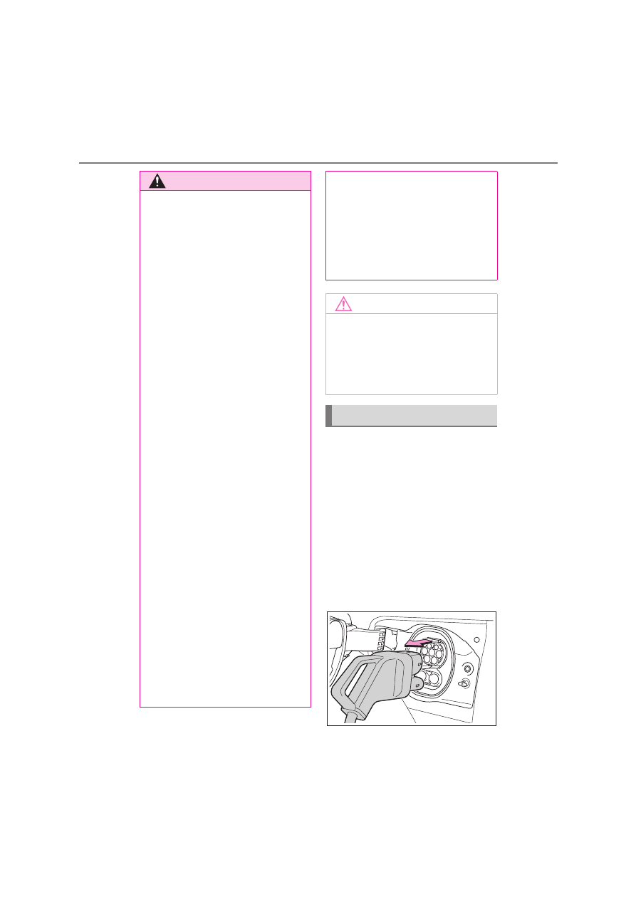
Remove the DC charging connec-
tor.

The DC charging connector shape and 

treatment will differ depending on the type 

of DC charger. Perform the operations in 

accordance to handling procedures of the 

DC charger.
Return the removed DC charging connec-

tor to its original position.

WARNING

Be sure the DC charging inlet makes 

direct contact with the DC charging 

connector.

Do not connect conversion adapters, 

extension cords, etc., between the DC 

charging connector and DC charging 

inlet.

When DC charging is interrupted, fol-

low the handling procedures of the 

DC charger. Immediately stop the DC 

charging when there is an outbreak of 

heat, smoke, strange noises or smells, 

etc., during charging.

Check that the DC charging connec-

tor and DC charging inlet do not have 

foreign objects or snow or ice 

attached to it. If anything is attached to 

the inlet, be sure to completely remove 

the material before connecting the DC 

charging connector.

Do not charge the vehicle when there 

is a possibility of lightning. If you notice 

lightning while charging the vehicle, do 

not touch the vehicle and the DC 

charging cable.

Do not get the DC charging inlet ter-

minals wet.

Close the hood when using DC charg-

ing. The cooling fan may suddenly start 

to run. Keep hands and clothing (espe-

cially a tie, a scarf or a muffler) away 

from the fan. Failure to do so may 

cause the hands or clothing to be 

caught, resulting in serious injury.

When connecting the DC charging 

connector

Follow the handling procedures of the 

DC charger to connect the DC charging 

connector. If the connector is not con-

nected properly, the system cannot rec-

ognize the connection, and it may be 

possible to start the EV system.

After charging is completed, make sure 

to remove the DC charging connector 

from the DC charging inlet before start-

ing the EV system.

If the vehicle is started off with the con-
nector still connected, it could lead to an 
accident, possibly resulting in death or 
serious injury.

NOTICE

When using DC charging

Make sure to follow the handling proce-

dures of the DC charger. If the proce-

dures are not followed properly, the 

vehicle and the DC charger may be 

damaged.

After charging

59

1

1-3. Charging with the EV system

Be

fore
 driving

3

Close the DC charging inlet cap, 
and then close the charging port 
lid.

When DC charging cannot be stopped

If charging cannot be stopped from the DC 

charger side due to a malfunction, etc.
You can also stop DC charging by pressing 

the door unlock button (on the electronic 

key, or driver’s door) three times at 1 to 2 

seconds intervals.

If the DC charging connector cannot be 

unlocked

P.570

After DC charging

Even if the traction battery is charged to the 

upper limit value that is set, the level of 

charge displayed on the DC charger may 

be lower than the actual one.

Calendar settings

The current date and time is automatically 

set using GPS. However, if the automatic 

setting of the clock is turned off on the 

center display, it will be necessary to manu-

ally set the date and time. For details, refer 

to the “MULTIMEDIA OWNER’S MAN-

UAL”.
If the calendar settings check screen is dis-

played when an attempt was made to regis-

ter a charge schedule, check that the 

correct date is set. If it is incorrect, be sure 

to correct it.
If the calendar information is wrong, the 

charging schedule function will not operate 

normally.

When registering the charging sched-
ule, the following settings can be 
changed.

Select the charging mode

One of the two following charging 
modes can be selected.

“Start at set time”

Starts charging at the set time

*

 and fin-

ishes charging when fully charged.

“Start and stop at set times”

AC charging is performed according 
to the set start time and stop time.

*

NOTICE

Caution after DC charging

Be sure to attach the DC charging inlet 

cap to the DC charging inlet and then 

close the charging port lid after remov-

ing the DC charging connector from the 

inlet. If the DC charging inlet cap or 

charging port lid is not closed, foreign 

materials may get into the inlet and the 

EV system may be malfunctioning.

Using the charging schedule 
function

AC charging can be carried out at 
the desired time by registering the 
charging schedule.

Settings of the charging sched-
ule function

60

1-3. Charging with the EV system

*

: There might be a slight error in the tim-

ing when charging starts due to the state 
of the traction battery.

Repeated setting

The periodic charging schedule can be 
set by selecting your desired day of the 
week. Select one or more day of the 
week to do the charging schedule.

Turning “Charge Now” on and off

To start charging without changing the 
charging schedule setting, turn 
“Charge Now” on to temporarily can-
cel the charging schedule and enable 
charging after connecting the AC 
charging connector.

*

*

: If the charging connector is removed 

during charging while the charging 
schedule is registered and “Charge 
Now” is on, “Charge Now” turns off.

“Next charging event”

Of the registered charging schedules, 
the closest charging schedule after the 
current time is called the “Next charg-
ing event”.
For charging schedule, AC charging 
will be performed according to the 
Next charging event.

The charging schedule can be regis-
tered on the center display. (

P.61)

Charging schedule

The charging schedule cannot be set 

while driving.

A maximum of 15 charging schedules 

can be registered.

If the charging mode is set to “Start and stop 

at set times” and the start time and stop time 

are set to the same time, charging will be 

performed for 24 hours from the start time.
The charging schedule function cannot be 

used when using DC charging.

To make sure that the charging schedule 

function operates correctly

Check the following items.

Adjust the clock to the correct time

*

The calendar is set to the correct date

*

Check that the power switch is turned off

After registering the charging schedule, 

connect the AC charging connector

The charging start time is determined 
based on the charging schedule at the time 
that the AC charging connector was con-
nected.

Connect the AC charging connector 

before the start time

When the charging mode is set to “Start at 
set time”, if you connect the AC charging 
connector after the set start time, the next 
charging schedule will be referenced.
When the charging mode is “Start and stop 
at set times”, if you connect the AC 
charging connector after the start time, 
charging will start immediately and 
charging will be performed until the stop 
time.

After connecting the AC charging con-

nector, check that the charging indicator 

of the charging port flashes (

P.50)

Do not use an socket that has a power cut 

off function (including a timer function)

Use an socket that constantly supplies 
electricity. For sockets where the power is 
cut off due to a timer function, etc., 
charging may not be carried out according 
to plan if the power is cut off during the set 

Registering the charging sched-
ule

61

1

1-3. Charging with the EV system

Be

fore
 driving

time.

*

: For the setting procedure for the clock 

and calendar, refer to “MULTIMEDIA 
OWNER’S MANUAL”.

When the AC charging connector 

remains connected to the vehicle

When the charging mode is set to “Start 

at set time”, even if multiple consecutive 

charging schedules are registered, the 

next charge will not be carried out 

according to the charging schedule until 

the AC charging connector is removed 

and reconnected after charging com-

pletes. Also, when the traction battery is 

fully charged, charging according to the 

charging schedule will not be carried out.

If the charging stop time is reached 

before the traction battery is fully 

charged and the charging mode is set to 

“Start and stop at set times”, the nearest 

charging schedule after the stop time is 

updated as the next charging schedule, 

and charging is repeated until the battery 

is fully charged.

Smartphone-linked operation (if 

equipped)

It may be necessary to use a smartphone 

with a dedicated app to change the charg-

ing settings.

When charging schedules are ignored

When the following operations are per-

formed while the charging schedule is on 

standby, charging schedule is temporarily 

canceled and charging is started.

When turning My Room Mode on 

(

P.64)

When turning “Charge Now” on 

(

P.63, 63)

When an operation that temporarily can-

cel charging using the charging schedule 

(

P.52)

Battery heater (

P.44)/Battery 

Cooler (

P.44)

Depending on the temperature of the trac-

tion battery, the traction battery heater or 

traction battery cooler may be activated 

and the charging indicator may light up 

while the timer is waiting for charging.

Setting operations related to the 
charging schedule are performed on 
the charging schedule screen.

Displaying the charging schedule 
screen

1

With the power switch in ON, 
select 

 on the center display.

Charging schedule settings cannot be 

changed when the power switch is in ACC.

2

Select “Charging schedule”.

How to read the charging schedule 
screen

Charging schedules

Displays the week-long registered charg-
ing schedule in a list using icons.

“Add” switch

Select to add a new item to the charging 
schedule. (

P.62)

“Edit” switch

Select to change or delete registered items 
on the charging schedule. (

P.62)

“Charge now” switch

Each time the button is selected, “Charge 
now” switches between on and off. 

Setting operations on center dis-
play

A

B

C

D

62

1-3. Charging with the EV system

(

P.62)

Registering the charging schedule

1

Display the “Charging schedule” 
screen. (

P.61)

2

Select “Add”.

The “Add event” screen will be displayed 

on the screen.

3

Change the schedule to the 
desired time.

Charging mode

Select “Start at set time” or “Start and stop 
at set times” to set the desired charging 
mode.
• When “Start at set time” is selected
Set the charging start time, and select 
“OK”.
• When “Start and stop at set times” is 

selected

Set the charging start time and stop time, 
and select “OK”.

Repeated settings

Select the day of the week and select 
“OK”.
When turned on, the charging schedule is 
repeated on that day. It is possible to turn 
more than one day on.

4

After setting operations are com-
plete, press “Save”.

The charging schedule is registered 
and an icon is added to the schedule.
To cancel registration of the charging 
schedule, select 

.

After setting operations are complete, 
when the power switch is turned off 
and the AC charging connector is con-
nected to the vehicle, charging is car-

ried out according to the charging 
schedule settings.

Switching charging schedules 
between on and off

1

Display the charging schedule 
screen. (

P.61)

2

Press “Edit”.

The “Events” screen will be displayed on 

the screen.

3

From the items displayed on the 

screen, select 

 or 


in the row of the charging schedule 
you wish to change.

If the charging schedule you wish to 
change is not displayed on the screen, 
scroll the list up and down to display it.
Each time the button is pressed, the 
charging schedule switches between 
on and off.

Changing the registered charging 
schedules

1

Display the “Charging schedule” 
screen. (

P.61)

2

Press “Edit”.

The “Events” screen will be displayed on 

the screen.

3

Press “Edit” on the “Events” screen.

4

From the items displayed on the 
screen, press the charging sched-
ule you wish to change.

Changing registered items:

Change the desired settings as described 
in step 

3

 to step 

4

 of the “Registering 

the charging schedule” procedure. 

(

P.62)

63

1

1-3. Charging with the EV system

Be

fore
 driving

When a setting is changed, its icon on the 
calendar also changes.

Deleting registered items:

Select “Delete”.
A deletion confirmation message will be 
displayed.
Press “Delete” to delete the selected 
charging schedule.
To cancel deletion, press “Cancel” or the 
return button.
When a charging schedule is deleted, its 
icon is also deleted from the calendar.

Turning “Charge now” on

1

Display the charging schedule 
screen. (

P.61)

2

Select 

 of “Charge now”.

Each time the button is pressed, 
“Charge now” switches between on 
and off.
After setting operations are complete, 
charging starts when the AC charging 
connector is connected.

Changing Next Event

If the customize content “ACC custom-
ise” is not set to OFF, the ending screen 
will not be displayed. If it is this case, 
check the settings on the center dis-
play. (

P.61)

Turn the power switch off.
Next event will be displayed according 
to the charging schedule settings.

When press “OK”, close Next 
charging event screen.

When press “Charge Now”, charge 

now is turned on.

When all charging schedules are turned 

off

The icon is not displayed on the charging 

schedule screen.
The icon will be displayed by turning it ON 

on the “Events” screen.

When charging schedule setting opera-

tions are canceled

When the vehicle is in the following condi-

tions, charging schedule setting operations 

are canceled.

The power switch is turned off before the 

settings are confirmed

The vehicle starts off

A display with a higher priority than that 

of the charging schedule setting is shown

“Next charging event”

After charging completes, the “Next charg-

ing event” on the display will not change 

until the AC charging cable is removed, 

after charging is performed according to 

the “Next charging event”.

Setting “Charge Now” to on

1

Turn the power switch off.

The closing display screen is displayed on 

the multi-information display.

(If the door is opened while waiting for 

charging schedule, the same screen will be 

displayed.)

NOTICE

While performing the setting opera-

tion

When performing the setting operation 

while the EV system is stopped, be care-

ful that the 12-volt battery will not be dis-

charged.

Setting operations on 
multi-information display

64

1-3. Charging with the EV system

2

Vehicles without a head-up display: 
Press 

 of the meter control 

switch.

*1

Vehicles with a head-up display: 
Press the steering wheel switch at 
the position where “Yes” is dis-
played on the multi-information dis-
play.

After setting operations are complete, 
charging starts when the AC charging 
connector is connected.

*1

: Each time 

 is pressed, “Charge 

now” will turn on/off.

When the power switch is turned off

When the power switch is turned off, the 

charging schedule (next scheduled charg-

ing) will be displayed on the closing display 

and the registered details can be 
checked.

*2

*2

: The closing display screen may not be 

displayed during charging.

1

Connect the charge cable to the 
vehicle to start charging.

AC Charging: 

P.50

DC Charging: 

P.55

2

Turn the power switch to ON while 
charging.

My Room Mode settings is automatically 

displayed on the center display.

3

Select “Yes”.

My Room Mode is started and it is possible 

to use the air conditioning system, audio 

system, etc.
When not using My Room Mode, select 

“No”.
To disable My Room Mode, turn the power 

switch off.
My Room Mode will automatically be off 

when DC charging is completed.

When a door is unlocked while using My 

Room Mode

If a door is unlocked while using My Room 

Mode, the AC charging connector will be 

unlocked and My Room Mode will be 

stopped. In order to use My Room Mode 

again, reconnect the AC charging cable 

and start My Room Mode (

P.64). When 

using My Room Mode with public charging 

station, operation to start charging using 

the charger may be required again before 

starting My Room Mode.

NOTICE

While performing the setting opera-

tion

When performing the setting operation 

while the EV system is stopped, be care-

ful that the 12-volt battery will not be dis-

charged.

Using My Room Mode

When the charging cable is con-
nected to the vehicle, electrical 
components such as the air condi-
tioning system and audio system 
can be used by the power supply 
from an external power source.

Starting My Room Mode

65

1

1-3. Charging with the EV system

Be

fore
 driving

Meter display while charging

After turning the power switch to ON while 

charging, the power switch automatically 

turns off if My Room Mode is not selected 

within approximately 100 seconds.

When using My Room Mode the follow-

ing may occur

When the remaining charge of the trac-

tion battery drops to the lower limit, the 

air conditioning system automatically 

stops. In that case, the air conditioning 

system cannot operate until the remain-

ing charge of the traction battery 

increases. Turn off the power switch once, 

then use My Room Mode after the 

remaining charge of the traction battery 

increases.

The charging time of the traction battery 

gets longer.

Noise may be heard from the radio 

depending on conditions of the radio 

wave.

The surrounding area of the onboard 

traction battery charger in the motor 

compartment may become hot.

The electric power steering system warn-

ing light (yellow) may turn on, but this is 

not a malfunction.

Using My Room Mode during DC 

charging

When using My Room mode during DC 

charging, the amount of charge at the time 

of charge completion will be lower than 

when not using it.
In addition, when DC charging in an envi-

ronment with low outside temperatures and 

high humidity, the air conditioner prioritizes 

dehumidification of the vehicle interior. This 

may lead to even lower charge at the time 

of completion.
When prioritizing the amount of charge, 

turn off the cooling and dehumidification 

functions. (

P.185, 209)

When a charging schedule is registered

When My Room Mode starts while the 

charging schedule is on standby, charging 

schedules are ignored and charging starts.

WARNING

Warnings for using My Room Mode

Observe the following precautions.

Failure to do so may result in death or a 

serious health hazard.

Do not leave children, people who 

need care, or pets inside the vehicle. 

The temperature inside the vehicle 

may become high or low due to fea-

tures such as the automatic shut-off. 

The children, people who need care, 

or pets left inside the vehicle may suf-

fer heatstroke dehydration or hypo-

thermia. Also, since the wipers, etc., 

can be operated, there may be acci-

dental operation, possibly leading to 

an accident.

Use the mode after sufficiently check-

ing the vicinity of the vehicle for safety 

hazards.

66

1-4. For safe driving with children on board

1-4.For safe driving with children on board

1

Unlock

2

Lock

These locks can be set to prevent children 
from opening the rear doors. Push down 
on each rear door switch to lock both rear 
doors.

Door opening method when using a 

child-protector lock

Unlock the door and press the door opener 

switch of the door handle and open the 

door. If it is necessary to open the door from 

inside the vehicle, open the rear side win-

dow and press the door opener switch of 

the door handle and open the door.

Riding with children

Observe the following precautions 
when children are in the vehicle.
Use a child restraint system appro-
priate for the child, until the child 
becomes large enough to properly 
wear the vehicle’s seat belt.

It is recommended that children 
sit in the rear seats to avoid acci-
dental contact with the rotary 
shifter, wiper switch, etc.

Use the rear door child-protector 
lock or the window lock switch to 
avoid children opening the door 
while driving or operating the 
power window accidentally. 
(

P.66, 110)

Do not let small children operate 
equipment which may catch or 
pinch body parts, such as the 
power window, hood, back door, 
seats etc.

WARNING

When children are in the vehicle

Never leave children unattended in the 

vehicle, and never allow children to have 

or use the key.

Children may be able to start the vehicle 

or shift the vehicle into neutral. There is 

also a danger that children may injure 

themselves by playing with the windows, 

or other features of the vehicle. In addi-

tion, heat build-up or extremely cold 

temperatures inside the vehicle can be 

fatal to children.

Preventing the rear doors from 
being opened from the inside of 
the vehicle (child-protector 
lock)

The door cannot be opened from 
inside the vehicle when the lock is 
set.

67

1

1-4. For safe driving with children on board

Be

fore
 driving

Points to remember: P.67
When using a child restraint system: 
P.68
Child restraint system compatibility for 
each seating position: P.71
Child restraint system installation 
method
• Fixed with a seat belt: P.78
• Fixed with an ISOFIX lower anchor-

age: P.79

• Using a top tether anchorage: P.80

Prioritize and observe the warn-
ings, as well as the laws and regula-
tions for child restraint systems.

Use a child restraint system until the 
child becomes large enough to 
properly wear the vehicle’s seat belt.

Choose a child restraint system 
appropriate to the age and size of 
the child.

Note that not all child restraint sys-
tems can fit in all vehicles.
Before using or purchasing a child 
restraint system, check the compati-
bility of the child restraint system 
with seat positions. (

P.71)

Child restraint systems

Before installing a child restraint 
system in the vehicle, there are pre-
cautions that need to be observed, 
different types of child restraint sys-
tems, as well as installation meth-
ods, etc., written in this manual.

Use a child restraint system when 
riding with a small child that can-
not properly use a seat belt. For 
the child’s safety, install the child 
restraint system to a rear seat. Be 
sure to follow the installation 
method that is in the operation 
manual enclosed with the 
restraint system.

The use of a Lexus genuine child 
restraint system is recom-
mended, as it is safer to use in this 
vehicle. Lexus genuine child 
restraint systems are made specif-
ically for Lexus vehicles. They can 
be purchased at a Lexus dealer.

Table of contents

Points to remember

WARNING

When a child is riding

Observe the following precautions.

Failure to do so may result in death or 

serious injury.

For effective protection in automobile 

accidents and sudden stops, a child 

must be properly restrained, using a 

seat belt or child restraint system 

which is correctly installed. For installa-

tion details, refer to the operation man-

ual enclosed with the child restraint 

system. General installation instruction 

is provided in this manual.

Lexus strongly urges the use of a 

proper child restraint system that con-

forms to the weight and size of the 

child, installed on the rear seat. 

According to accident statistics, the 

child is safer when properly restrained 

in the rear seat than in the front seat.

68

1-4. For safe driving with children on board

When installing a child restraint 
system to a front passenger seat

For the safety of a child, install child 
restraint systems to a rear seats. When 
installing child restraint system to a 
front passenger seat is unavoidable, 
adjust the seat as follows and install the 
child restraint system.

Move the seat fully rearward.

Move the seat height to the upper 
most position.

Adjust the seatback angle to the 
most upright position.

When installing a forward-facing child 
seat, if there is a gap between the child seat 
and the seatback, adjust the seatback 
angle until good contact is achieved.

If the head restraint interferes with 
your child restraint system, and the 
head restraint can be removed, 
remove the head restraint.

Otherwise, put the head restraint in the 
upper most position.

WARNING

Holding a child in your or someone 

else’s arms is not a substitute for a child 

restraint system. In an accident, the 

child can be crushed against the wind-

shield or between the holder and the 

interior of the vehicle.

Handling the child restraint system

If the child restraint system is not prop-

erly fixed in place, the child or other pas-

sengers may be seriously injured or even 

killed in the event of sudden braking, sud-

den swerving, or an accident.

If the vehicle were to receive a strong 

impact from an accident, etc., it is pos-

sible that the child restraint system has 

damage that is not readily visible. In 

such cases, do not reuse the restraint 

system.

Depending on the child restraint sys-

tem, installation may be difficult or 

impossible. In those cases, check 

whether the child restraint system is 

suitable for installment in the vehicle. 

(

P.71) Be sure to install and observe 

the usage rules after carefully reading 

the child restraint system fixing 

method in this manual, as well as the 

operation manual enclosed with the 

child restraint system.

Keep the child restraint system prop-

erly secured on the seat even if it is not 

in use. Do not store the child restraint 

system unsecured in the passenger 

compartment.

If it is necessary to detach the child 

restraint system, remove it from the 

vehicle or store it securely in the lug-

gage compartment.

When using a child restraint sys-
tem

69

1

1-4. For safe driving with children on board

Be

fore
 driving

WARNING

When using a child restraint system

Observe the following precautions.

Failure to do so may result in death or 

serious injury.

Never use a rear-facing child restraint 

system on the front passenger seat 

when the airbag manual on-off switch 

is on. (

P.82)

The force of the rapid inflation of the 

front passenger airbag can cause 

death or serious injury to children in 

the event of an accident.

There is a label(s) on the passenger 

side sun visor, indicating it is forbidden 

to attach a rear-facing child restraint 

system to the front passenger seat.

Details of the label(s) are shown in the 

illustration below.

70

1-4. For safe driving with children on board

WARNING

WARNING

Only put a forward-facing child 

restraint system on the front seat when 

unavoidable. When installing a for-

ward-facing child restraint on the front 

passenger seat, move the seat as far 

back as possible. Failing to do so may 

result in death or serious injury if the 

airbags deploy (inflate).

Do not allow the child to lean his/her 

head or any part of his/her body 

against the door or the area of the seat, 

front or rear pillars, or roof side rails 

from which the SRS side airbags or 

SRS curtain shield airbags deploy even 

if the child is seated in the child 

restraint system. It is dangerous if the 

SRS side airbags and curtain shield 

airbags inflate, and the impact could 

cause death or serious injury to the 

child.

When a junior seat is installed, always 

ensure that the shoulder belt is posi-

tioned across the center of the child’s 

shoulder. The belt should be kept away 

from the child’s neck, but not so that it 

could fall off the child’s shoulder.

Use child restraint system suitable to 

the age and size of the child and install 

it to the rear seat.

71

1

1-4. For safe driving with children on board

Be

fore
 driving

Child restraint system compatibil-
ity for each seating position

Compatibility of each seating position 
with child restraint systems (

P.72) 

displays the type of child restraint sys-
tems that can be used and possible 
seating positions for installation using 
symbols. Also, the recommended child 
restraint system that is suitable for your 
child can be selected.
Otherwise, check [Recommended 
child restraint systems information] for 
recommended child restraint systems. 
(

P.76)

Check the selected child restraint sys-
tem together with the following 
[Before confirming the compatibility of 
each seating position with child 
restraint systems].

Before confirming the compatibil-
ity of each seating position with 
child restraint systems

1

Checking the child restraint system 
standards.
Use a child restraint system that 
conforms to UN(ECE) R44

*1

 or 

UN(ECE) R129

*1, 2

.

The following approval mark is dis-
played on child restraint systems 
which are conformed.
Check for an approval mark 
attached to the child restraint sys-
tem.

Example of the displayed regulation num-
ber

UN(ECE) R44 approval mark

*3

The weight range of the child who is 
applicable for an UN(ECE) R44 
approval mark is indicated.

UN(ECE) R129 approval mark

*3

The height range of the child who is 
applicable as well as available 
weights for an UN(ECE) R129 
approval mark is indicated.

WARNING

If the driver’s seat interferes with the 

child restraint system and prevents it 

from being attached correctly, attach 

the child restraint system to the 

right-hand rear seat (left-hand drive 

vehicles) or the left-hand rear seat 

(right-hand drive vehicles).

Child restraint system compati-
bility for each seating position

A

B

72

1-4. For safe driving with children on board

2

Checking the category of the child 
restraint system.
Check the approval mark of the 
child restraint system for which of 
the following categories the child 
restraint system is suitable.
Also, if there are any uncertainties, 
check the user’s guide included 
with the child restraint system or 
contact the retailer of the child 
restraint system.

• “universal”
• “semi-universal”
• “restricted”
• “vehicle specific”

*1

: UN(ECE) R44 and UN(ECE) R129 

are U.N. regulations for child restraint 
systems.

*2

: The child restraint systems mentioned in 

the table may not be available outside of 
the EU area.

*3

: The displayed mark may differ depend-

ing on the product.

Compatibility of each seating posi-
tion with child restraint systems

Left-hand drive vehicles

Right-hand drive vehicles

73

1

1-4. For safe driving with children on board

Be

fore
 driving

*1

: Move the front seat fully rearward. If the 

passenger seat height can be adjusted, 
move it to the upper most position.

*2

: Adjust the seatback angle to the most 

upright position. When installing a for-
ward-facing child seat, if there is a gap 
between the child seat and the 
seatback, adjust the seatback angle 
until good contact is achieved.

*3

: If the head restraint interferes with your 

child restraint system, and the head 
restraint can be removed, remove the 
head restraint.
Otherwise, put the head restraint in the 
upper most position.

*4

: Not suitable for child restraint systems 

with support leg.

*5

: Applicable for KIDFIX i-SIZE only.

When securing some types of child 
restraint systems in rear seat, it may not 
be possible to properly use the seat 
belts in positions next to the child 
restraint without interfering with it or 
affecting seat belt effectiveness. Be 
sure your seat belt fits snugly across 
your shoulder and low on your hips. If it 
does not, or if it interferes with the child 
restraint, move to a different position. 
Failure to do so may result in death or 
serious injury.

When installing a child restraint in 
the rear seats, adjust the front seat 
so that it does not interfere with the 
child or child restraint system.

When installing a child seat with 
support base, if the child seat inter-
feres with the seatback when latch-
ing it into the support base, adjust 
the seatback rearward until there is 
no interference.

If the seat belt shoulder anchor is 
ahead of the child seat belt guide, 
move the seat cushion forward.

Deactivation of front passenger 
airbag.
Activation of front passenger 
airbag.
Never use a rearward-facing child 
restraint system on the front pas-
senger seat when the airbag man-
ual on-off switch is on.
Suitable for “universal” category 
child restraint system fixed with 
the seat belt.
Suitable for forward-facing “uni-
versal” category child restraint 
system fixed with the seat belt.
Suitable for recommended child 
restraint systems given on recom-
mended child restraint systems 
information (

P.76).

Suitable for i-Size and ISOFIX 
child restraint system.

Includes a top tether anchorage 
point.

74

1-4. For safe driving with children on board

When installing a junior seat, if the 
child in your child restraint system is 
in a very upright position, adjust the 
seatback angle to the most comfort-
able position. And if the seat belt 
shoulder anchor is ahead of the 
child seat belt guide, move the seat 
cushion forward.

Detail information for child restraint systems installation

Seating position

Seat position number

*2

Airbag manual on-off 

switch

ON

OFF

Left

Center

Right

Seating position suita-

ble for universal belted 

(Yes/No)

Yes

For-

ward-fac-

ing only

Yes

*1

Yes

*1

Yes

*1

Yes

*1

i-Size seating position 

(Yes/No)

No

No

Yes

No

Yes

Seating position suita-

ble for lateral fixture 

(L1/L2/No)

No

No

No

No

No

Suitable rearward fac-

ing fixture 

(R1/R2X/R2/R3/No)

No

No

R1, R2X, 

R2, R3

No

R1, R2X, 

R2, R3

Suitable forward facing 

fixture 

(F2X/F2/F3/No)

No

No

F2X, F2, F3

No

F2X, F2, F3

Suitable junior seat fix-

ture (B2/B3/No)

B2, B3

Belt fixa-

tion only

B2, B3

Belt fixa-

tion only

B2, B3

No

B2, B3

75

1

1-4. For safe driving with children on board

Be

fore
 driving

*1

: All universal categories (group 0, 0+, I, II and III).

*2

: Not suitable for child restraint systems with support leg.

LEXUS suggests the users to use 

 and 

 seating positions.

ISOFIX child restraint systems are divided into different “fixture”. The child 
restraint system can be used in the seating positions for “fixture” mentioned in the 
table above. For kind of “fixture” relation, confirm the following table.
If your child restraint system has no kind of “fixture” (or if you cannot find informa-
tion in the table below), please refer to the child restraint system “vehicle list” for 
compatibility information or ask the retailer of your child seat.

Mass 

groups

Child weight

Size 

class

Fixture

Description

0

up to 10 kg 

(22 lb.)

E

R1

Rearward-facing infant seat

F

L1

Left lateral-facing infant seat (Carrycot)

G

L2

Right lateral-facing infant seat (Carrycot)

0+

up to 13 kg 

(28 lb.)

C

R3

Full-size, rearward-facing child restraint 

systems

D

R2

Reduced-size, rearward-facing child 

restraint systems

R2X

Reduced-size, rearward-facing child 

restraint systems

E

R1

Rearward-facing infant seat

I

9 to 18 kg (20 

to 39 lb.)

A

F3

Full-height, forward-facing child restraint 

systems

B

F2

Reduced-height, forward-facing child 

restraint systems

B1

F2X

Reduced-height, forward-facing child 

restraint systems

C

R3

Full-size, rearward-facing child restraint 

systems

D

R2

Reduced-size, rearward-facing child 

restraint systems

76

1-4. For safe driving with children on board

Recommended child restraint systems information

*1

: Be sure attach the seat belt through the SecureGuard.

*2

: LEXUS recommends to use with lower anchorages.

The child restraint systems mentioned in the table may not be available outside the 

EU countries and United Kingdom.

When using the child restraint sys-
tem with SecureGuard, be sure to 
guide the lap belt into SecureGuard 

 as shown in the illustration.

II

15 to 25 kg 

(34 to 55 lb.)

B2, B3

Junior seat

III

22 to 36 kg 

(48 to 79 lb.)

Recommended child 

restraint system

Size

Direction of 

travel

Fixation

fixed with 

lower anchor-

ages

fixed with a 

seat belt

MAXI COSI PEARL 

360 & FAMILYFIX 

360 BASE

40 to 105 cm (16 

to 41 in.)

Rear-

ward-facing

Yes

Not applica-

ble

Up to 17.5 kg (Up 

to 38 lb.)

> 15 month & 76 

to 105 cm (30 to 

41 in.)

Forward-fac-

ing

Up to 17.5 kg (Up 

to 38 lb.)

LEXUS KIDFIX 

i-SIZE

*1, 2

100 to 150 cm 

(39 to 59 in.)

Forward-fac-

ing use only

Yes

Yes

15 to 36 kg (34 to 

79 lb.)

Mass 

groups

Child weight

Size 

class

Fixture

Description

A

77

1

1-4. For safe driving with children on board

Be

fore
 driving

Confirm with the operation manual enclosed with the child restraint system about 
the installation of the child restraint system.

Child restraint system installation method

Installation method

Page

Seat belt attachment

P.78

ISOFIX lower anchorages 

attachment

P.79

Top tether anchorage 

attachment

P.80

78

1-4. For safe driving with children on board

Installing child restraint system 
using a seat belt

Install the child restraint system in 
accordance to the operation manual 
enclosed with the child restraint sys-
tem.
If the child restraint system on hand is 
not within the “universal” category (or 
the necessary information is not in the 
table), refer to the “Vehicle List” pro-
vided by the child restraint system 
maker for various possible installation 
positions, or check the compatibility 
after asking the retailer of the child 
seat. (

P.71)

1

If installing the child restraint sys-
tem to the front passenger seat is 
unavoidable, refer to P.68for the 
front passenger seat adjustment.

2

Adjust the seatback angle to the 
most upright position.

When installing a forward-facing child 

seat, if there is a gap between the child seat 

and the seatback, adjust the seatback 

angle until good contact is achieved.

3

If the head restraint interferes with 
the child restraint system installa-
tion and the head restraint can be 
removed, remove the head 
restraint. Otherwise, put the head 
restraint in the upper most position. 
(

P.130)

4

Run the seat belt through the child 
restraint system and insert the plate 
into the buckle. Make sure that the 

belt is not twisted. Securely fix the 
seat belt to the child restraint sys-
tem in accordance to the directions 
enclosed with the child restraint 
system.

5

If your child restraint system is not 
equipped with a lock-off (a seat belt 
locking feature), secure the child 
restraint system using a locking clip.

6

After installing the child restraint 
system, rock it back and forth to 
ensure that it is installed securely. 
(

P.79)

Removing a child restraint system 
installed with a seat belt

Press the buckle release button and 
fully retract the seat belt.

When releasing the buckle, the child 
restraint system may spring up due to the 
rebound of the seat cushion. Release the 
buckle while holding down the child 

Child restraint system fixed with 
a seat belt

79

1

1-4. For safe driving with children on board

Be

fore
 driving

restraint system.
Since the seat belt automatically reels itself, 
slowly return it to the stowing position.

When installing a child restraint system

You may need a locking clip to install the 

child restraint system. Follow the instruc-

tions provided by the manufacturer of the 

system. If your child restraint system does 

not provide a locking clip, you can purchase 

the following item from any authorized 

Lexus retailer or Lexus authorized repairer, 

or any reliable repairer: Locking clip for 

child restraint system

(Part No. 73119-22010)

ISOFIX lower anchorages 
(ISOFIX child restraint system)

Lower anchorages are provided for the 
outboard seats. (Buttons displaying the 
location of the anchorages are 
attached to the seats.)

Installation with ISOFIX lower 
anchorages (ISOFIX child 
restraint system)

Install the child restraint system in 
accordance to the operation manual 
enclosed with the child restraint sys-
tem.
If the child restraint system on hand is 
not within the “universal” category (or 
the necessary information is not in the 
table), refer to the “Vehicle List” pro-

WARNING

When installing a child restraint sys-

tem

Observe the following precautions.

Failure to do so may result in death or 

serious injury.

Do not allow children to play with the 

seat belt. If the seat belt becomes 

twisted around a child’s neck, it may 

lead to choking or other serious inju-

ries that could result in death. If this 

occurs and the buckle cannot be 

unfastened, scissors should be used to 

cut the belt.

Ensure that the belt and plate are 

securely locked and the seat belt is not 

twisted.

Shake the child restraint system left 

and right, and forward and backward 

to ensure that it has been securely 

installed.

After securing a child restraint system, 

never adjust the seat.

When a junior seat is installed, always 

ensure that the shoulder belt is posi-

tioned across the center of the child’s 

shoulder. The belt should be kept away 

from the child’s neck, but not so that it 

could fall off the child’s shoulder.

Follow all installation instructions pro-

vided by the child restraint system 

manufacturer.

Child restraint system fixed with 
ISOFIX lower anchorages

80

1-4. For safe driving with children on board

vided by the child restraint system 
maker for various possible installation 
positions, or check the compatibility 
after asking the retailer of the child 
seat. (

P.71)

1

Adjust the seatback angle to the 
most upright position.

When installing a forward-facing child 

seat, if there is a gap between the child seat 

and the seatback, adjust the seatback 

angle until good contact is achieved.

2

If the head restraint interferes with 
the child restraint system installa-
tion and the head restraint can be 
removed, remove the head 
restraint. Otherwise, put the head 
restraint in the upper most position. 
(

P.130)

3

Check the positions of the exclu-
sive fixing bars, and install the child 
restraint system to the seat.

The bars are installed in the clearance 

between the seat cushion and seatback.

4

After installing the child restraint 
system, rock it back and forth to 
ensure that it is installed securely. 
(

P.79)

Top tether anchorages

Top tether anchorages are provided 
for the outboard seats.
Use top tether anchorages when fixing 
the top strap.

Top tether anchorages
Top strap

WARNING

When installing a child restraint sys-

tem

Observe the following precautions. 

Failure to do so may result in death or 

serious injury.

After securing a child restraint system, 

never adjust the seat.

When using the lower anchorages, be 

sure that there are no foreign objects 

around the anchorages and that the 

seat belt is not caught behind the child 

restraint system.

Follow all installation instructions pro-

vided by the child restraint system 

manufacturer.

Using a top tether anchorage

A
B

81

1

1-4. For safe driving with children on board

Be

fore
 driving

Fixing the top strap to the top 
tether anchorages

Install the child restraint system in 
accordance to the operation manual 
enclosed with the child restraint sys-
tem.

1

Remove the head restraint if it inter-
feres with your child restraint sys-
tem. (

P.130)

If the head restraint cannot be removed, 

raise it to the uppermost position.

2

Latch the hook onto the top tether 
anchorage and tighten the top 
strap.

Make sure the top strap is securely latched. 

(

P.79)

When installing the child restraint system 

with the head restraint being raised, be 

sure to have the top strap pass underneath 

the head restraint.

Hook
Top strap

A
B

WARNING

When installing a child restraint sys-

tem

Observe the following precautions.

Failure to do so may result in death or 

serious injury.

Firmly attach the top strap and make 

sure that the belt is not twisted.

Do not attach the top strap to anything 

other than the top tether anchorage of 

the seat the child restraint system is 

installed to.

After securing a child restraint system, 

never adjust the seat.

Follow all installation instructions pro-

vided by the child restraint system 

manufacturer.

When installing the child restraint sys-

tem with the head restraint being 

raised, after the head restraint has 

been raised and then the top tether 

anchorage has been fixed, do not 

lower the head restraint.

82

1-4. For safe driving with children on board

This system deactivates the following 
SRS airbags:

SRS front passenger airbag

SRS front passenger knee airbag

Only deactivate the airbags when 
using a child restraint system on the 
front passenger seat.

“PASSENGER AIR BAG” indica-
tor

“PASSENGER AIR BAG” and “ON” indi-
cator light turns on when the airbag system 
is on, and about after 60 seconds they go 
off. (only when the power switch is in ON).

Airbag manual on-off switch

Insert the key into the cylinder and turn 
to the “OFF” position.

The “OFF” indicator light turns on (only 
when the power switch is in ON).

“PASSENGER AIR BAG” indicator 

information

If any of the following problems occur, it is 

possible that there is a malfunction in the 

system. Have the vehicle inspected by any 

authorized Lexus retailer or Lexus author-

ized repairer, or any reliable repairer.

The “OFF” indicator does not illuminate 

when the airbag manual on-off switch is 

set to “OFF”.

The indicator light does not change when 

the airbag manual on-off switch is 

switched to “ON” or “OFF”.

Airbag manual on-off system

A

B

Deactivating the airbags for the 
front passenger

83

1

1-4. For safe driving with children on board

Be

fore
 driving

WARNING

When installing a child restraint sys-

tem

For safety reasons, always install a child 

restraint system in a rear seat. In the 

event that the rear seat cannot be used, 

the front seat can be used as long as the 

airbag manual on-off system is set to 

“OFF”.

If the airbag manual on-off system is left 

on, the strong impact of the airbag 

deployment (inflation) may cause serious 

injury or even death.

When a child restraint system is not 

installed on the front passenger seat

Ensure that the airbag manual on-off sys-

tem is set to “ON”.

If it is left off, the airbag may not deploy in 

the event of an accident, which may 

result in serious injury or even death.

84

1-5. Entering/exiting the vehicle

1-5.Entering/exiting the vehicle

The following keys are provided with 
the vehicle.

Electronic keys

• Operating the smart entry & start sys-

tem (

P.87)

• Operating the wireless remote control 

function (

P.94)

Mechanical keys
Key number plate
Card key (electronic key) (if 
equipped)

Operating the smart entry & start system 
(

P.87)

Key types

NOTICE

To prevent key damage

Observe the following precautions

Do not drop the keys, subject them to 

strong shocks or bend them.

Do not expose the keys to high tem-

peratures for long periods of time.

Do not get the keys wet or wash them 

in an ultrasonic washer, etc.

A

B
C
D

Do not attach metallic or magnetic 

materials to the keys or place the keys 

close to such materials.

Do not disassemble the keys.

Do not attach a sticker or anything else 

to the surface of the electronic key.

Do not place the keys near objects that 

produce magnetic fields, such as TVs, 

audio systems and induction cookers.

Do not place the keys near medical 

electrical equipment such as low-fre-

quency therapy equipment or micro-

wave therapy equipment, and do not 

receive medical attention with the keys 

on your person.

Carrying the electronic key on your 

person

Carry the electronic key 10 cm (3.9 in.) 

or more away from electric appliances 

that are turned on. Radio waves emitted 

from electric appliances within 10 cm 

(3.9 in.) of the electronic key may inter-

fere with the key, causing the key to not 

function properly.

Handling the card key

If the battery or card key terminals get 

wet, the battery may corrode and the 

card key may stop working.If the key is 

dropped into water, or if drinking 

water, etc., is spilled on the key, imme-

diately remove the battery cover and 

wipe the battery and terminals. (To 

remove the battery cover, lightly grasp 

and pull it.) If the battery is corroded, 

have any authorized Lexus retailer or 

Lexus authorized repairer, or any relia-

ble repairer replace the battery.

Do not crush the battery cover or use 

a screwdriver to remove the battery 

cover. Forcibly removing the battery 

cover may bend or damage the key.

If the battery cover is frequently 

removed, the battery cover may 

become loose.

85

1

1-5. Entering/exiting the vehicle

Be

fore
 driving

Handling the card key

The mechanical key that is stored inside 

the card key should be used only if a 

problem arises, such as when the card 

key does not operate properly.

If the battery cover is not installed and the 

battery falls out or if the battery was 

removed because the key got wet, rein-

stall the battery with the positive terminal 

facing the Lexus emblem.

The card key is not waterproof.

When riding in an aircraft

When bringing an electronic key onto an 

aircraft, make sure you do not press any 

buttons on the electronic key while inside 

the aircraft cabin. If you are carrying an 

electronic key in your bag, etc., ensure that 

the buttons are not likely to be pressed acci-

dentally. Pressing a button may cause the 

electronic key to emit radio waves that 

could interfere with the operation of the air-

craft.

Electronic key battery depletion

The standard battery life is 1 to 2 years. 

(The card key battery life is from one year 

to one year and a half.)

If the battery becomes low, an alarm will 

sound in the cabin when the EV system 

stops.

As the electronic key always receives 

radio waves, the battery will become 

depleted even if the electronic key is not 

used. The following symptoms indicate 

that the electronic key battery may be 

depleted. Replace the battery when nec-

essary.

• The smart entry & start system or the 

wireless remote control does not oper-

ate.

• The detection area becomes smaller.

• The LED indicator on the key surface 

does not turn on.

You can replace the battery by yourself 

(

P.552). However, as there is a danger 

that the electronic key may be damaged, 

it is recommended that replacement is 

carried out ask any authorized Lexus 

retailer or Lexus authorized repairer, or 

any reliable repairer for details.

To avoid serious deterioration, do not 

leave the electronic key within 1 m (3 ft.) 

of the following electrical appliances that 

produce a magnetic field:

• TVs

• Personal computers

• Cellular phones, cordless phones and 

battery chargers

• Table  lamps

• Induction cookers

Battery-saving function

The battery-saving function will be acti-

vated in order to prevent the electronic key 

battery and the 12-volt battery from being 

discharged while the vehicle is not in opera-

tion for a long time.

In the following situations, the smart entry 

& start system may take some time to 

unlock the doors.

NOTICE

When installing the battery, make sure 

to check the direction of the bat-

tery.Installing the battery in the wrong 

direction may cause the battery to 

deplete rapidly.

The surface of the card key may be 

damaged, or its coating may peel off in 

the following situations:

• The card key is carried together with 

hard objects, such as coins and keys.

• The card key is scraped with a sharp 

object, such as the tip of a mechanical 

pencil.

• The surface of the card key is wiped 

with thinner or benzene.

86

1-5. Entering/exiting the vehicle

• The electronic key has been left in an 

area of approximately 3.5 m (11 ft.) of the 

outside of the vehicle for 10 minutes or 

longer.

• The smart entry & start system has not 

been used for 5 days or longer.

If the smart entry & start system has not 

been used for 14 days or longer, the 

doors cannot be unlocked at any doors 

except the driver’s door. In this case, take 

hold of the driver’s door handle, or use 

the wireless remote control or the 

mechanical key, to unlock the doors.

Electronic key battery-saving mode

When battery-saving mode is set, battery 

depletion is minimized by stopping the 

electronic key from receiving radio 

waves.

While pressing and holding 

 on the 

electronic key, press 

 twice. The indica-

tor on the electronic key will flash 4 times 

and battery-saving mode will be entered.
The smart entry & start system cannot be 

used while the electronic key is in bat-

tery-saving mode. Battery saving mode 

can be cancelled by pressing any switch on 

the electronic key.

Electronic keys that will not be used for 

long periods of time can be set to the bat-

tery-saving mode in advance.

When electronic key function stops

If the position of the electronic key has not 

changed for a certain amount of time such 

as when the electronic key is left some-

where, the function of the electronic key 

stops to reduce depletion of the battery.

Confirmation of the registered key 

number

The number of keys already registered to 

the vehicle can be confirmed. Ask any 

authorized Lexus retailer or Lexus author-

ized repairer, or any reliable repairer for 

details.

87

1

1-5. Entering/exiting the vehicle

Be

fore
 driving

Antenna location

Antennas outside the cabin
Antennas inside the cabin
Antenna outside the luggage compart-
ment
Antennas outside the cabin (Vehicles 
with Lexus Teammate Advanced Park 
system)

Effective range (areas within which the 

electronic key is detected)

When locking or unlocking the doors

The system can be operated when the 
electronic key is within about 0.7 m (2.3 ft.) 
of an outside door handle. (Only the doors 
detecting the key can be operated.)

When starting the EV system or 
changing power switch modes

The system can be operated when the 

Smart entry & start system

WARNING

Affects influenced by the radio wave 

(Affect from the Smart entry & start 

system antennas)

People with implantable cardiac pace-

makers, cardiac resynchronization 

therapy-pacemakers or implantable 

cardioverter defibrillators should 

maintain a reasonable distance 

between themselves and the smart 

entry & start system antennas. The 

radio waves may affect the operation 

of such devices. If necessary, the entry 

function can be disabled. Ask any 

authorized Lexus retailer or Lexus 

authorized repairer, or any reliable 

repairer for details, such as the fre-

quency of radio waves and timing of 

the emitted radio waves. Then, consult 

your doctor to see if you should disa-

ble the entry function.

Users of any electrical medical device 

other than implantable cardiac pace-

makers, cardiac resynchronization 

therapy-pacemakers or implantable 

cardioverter defibrillators should con-

sult the manufacturer of the device for 

information about its operation under 

the influence of radio waves. Radio 

waves could have unexpected effects 

on the operation of such medical 

devices.

Ask any authorized Lexus retailer or 

Lexus authorized repairer, or any reliable 

repairer for details on disabling the entry 

function.

A
B
C

D

A

B

88

1-5. Entering/exiting the vehicle

electronic key is inside the vehicle.

If an alarm sounds or a warning message 

is displayed

A combination of exterior and interior 

alarms as well as warning messages shown 

on the multi-information display are used to 

prevent theft of the vehicle and accidents 

resulting from erroneous operation. Take 

appropriate measures in response to any 

warning message on the multi-information 

display. (

P.510)

The following table describes situations and 

correction procedures when only an alarm 

sounds.

When an exterior alarm sounds once for 

5 seconds

Situation: An attempt was made to lock the 
vehicle while a door was open.
Correction procedure: Close all of the 
doors and lock the doors again.

When an interior alarm pings repeatedly

Situation: The power switch was turned to 
ACC while the driver’s door was open 
(The driver’s door was opened when the 
power switch was in ACC).
Correction procedure: Turn the power 
switch off and close the driver’s door.

Conditions affecting operation

The smart entry & start system, wireless 

remote control and immobilizer system use 

weak radio waves. In the following situa-

tions, the communication between the elec-

tronic key and the vehicle may be affected, 

preventing the smart entry & start system, 

wireless remote control and immobilizer 

system from operating properly. (Ways of 

coping:

P.554)

When the electronic key battery is 

depleted

Near a TV tower, electric power plant, 

gas station, radio station, large display, 

airport or other facility that generates 

strong radio waves or electrical noise

When the electronic key is in contact 

with, or is covered by the following metal-

lic objects

• Cards to which aluminum foil is attached

• Cigarette boxes that have aluminum foil 

inside

• Metallic wallets or bags

• Coins

• Hand warmers made of metal

• Media such as CDs and DVDs

When other wireless keys (that emit radio 

waves) are being used nearby

When carrying the electronic key 

together with the following devices that 

emit radio waves

• Portable radio, cellular phone, cordless 

phone or other wireless communication 

devices

• Another vehicle’s electronic key or a 

wireless key that emits radio waves

• Personal computers or personal digital 

assistants (PDAs)

• Digital audio players

• Portable game systems

If window tint with a metallic content or 

metallic objects are attached to the rear 

window

When the electronic key is placed near a 

battery charger or electronic devices

When the vehicle is parked in a pay park-

ing spot where radio waves are emitted

If the doors cannot be locked/unlocked 

using the smart entry & start system, 

lock/unlock the doors by performing any of 

the following:

Bring the electronic key close to either 

front door handle and operate the entry 

function.

Operate the wireless remote control. If 

the doors cannot be locked/unlocked 

using the above methods, use the 

mechanical key. (

P.554)

If the EV system cannot be started using 

the smart entry & start system, refer to 

P.532.

Note for the entry function

Even when the electronic key is within the 

effective range (detection areas), the sys-

tem may not operate properly in the fol-

lowing cases:


Content      ..      1      2      3      ..