Harley Davidson 1999-2005 Harley Dyna Models. Repair Manual - page 19
-------------------------------------------------------------------------------------------------------------------------------------------------------------
360
CHAPTER EIGHT
136
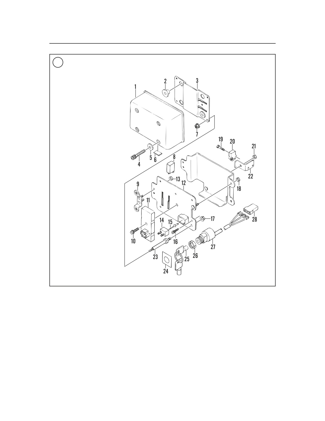
ELECTRICAL PANEL (1999-2000)
1.
Cover
2.
Grommet
3.
Outer plate
4.
Bolt
5.
Washer
6.
Label
7.
Nut
8.
Starter relay (diode)
9.
Mounting bracket
10.
Bolt
11.
Turn signal canceller
module (TSM)
12.
Electrical panel
13.
Nut
14.
Circuit breaker-30
amp
15.
Pop rivet
16.
Screw
17.
Nut
18.
Nut
19.
Bolt
20.
Bank angle sensor
21.
Nut
22.
Bracket
23.
Stand off stud
24.
Decal
25.
Ignition key
26.
Face nut
27.
Ignition switch
28.
Electrical connector
1. When the left turn signal switch is pressed, a mo-
3. When the right turn signal switch is pressed, a
mentary 12 VDC pulse is sent to Pin No. 8 (input)
momentary 12 VDC pulse is sent to Pin No. 7 (in-
on the TSM module. The module responds to this
put) on the TSM module and an output signal at Pin
signal by sending a series of 12 VDC pulses to Pin
No. 3 (output). The remaining signal process is
No. 4 (output) to flash the left front and rear turn
identical to the left turn signal operation.
signal lamps.
2. The TSM module then monitors the number of
Preliminary Troubleshooting
vehicle speed sensor pulses sent from the speed-
ometer sending unit to Pin No. 3. These pulses in-
dicate the distance the motorcycle has traveled.
If one or all of the turn signals do not flash, per-
When the number of speedometer pulses is equal
form the following:
to the quantity preset in the module program, the
1. Remove the lens and check for a defective
turn signal is cancelled.
bulb(s). Replace the bulb(s) if necessary.