Harley Davidson 1999-2005 Harley Dyna Models. Repair Manual - page 17
-------------------------------------------------------------------------------------------------------------------------------------------------------------
320
CHAPTER EIGHT
ignition module where the module adjusts the igni-
tion timing advance curve for maximum perfor-
33
mance.
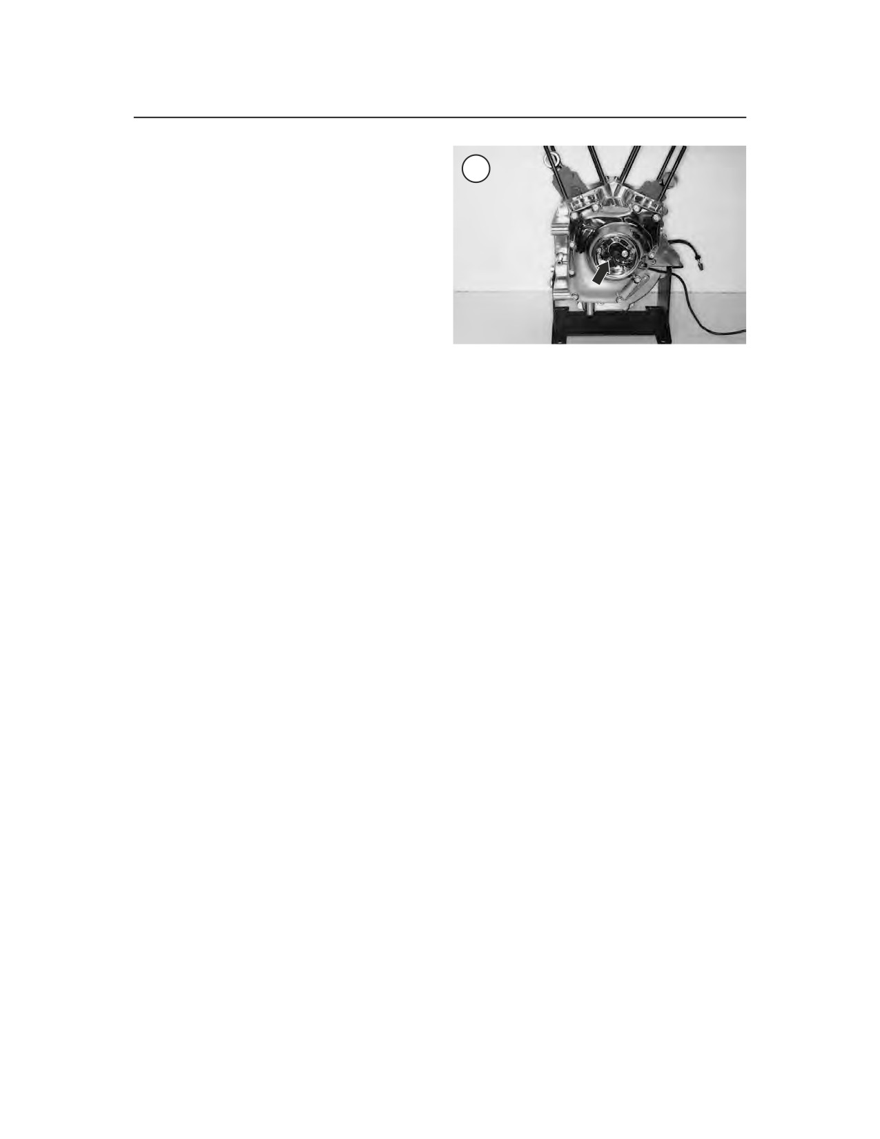
On 1999-2000 models, the camshaft position
sensor (CMP) (Figure 33) is located in the cam-
shaft cover on the right side of the crankcase. The
raised ridge on the rotor operates at one-half crank-
shaft speed and it breaks the magnetic field of the
Hall-effects device on the camshaft position sen-
sor. The logic-type signal of the Hall-effect device
gives accurate timing information to the ignition
module.
The bank angle sensor mounts on a
2. Insert a clean shop cloth into the spark plug hole
frame-mounted panel behind the electric panel, on
in the cylinder head to lessen the chance of gasoline
the left side of the motorcycle on 1999-2000 mod-
vapors being emitted from the hole.
els. On 2001-on models, the bank angle sensor is
an integral part of the turn signal/turn signal secu-
3. Insert the spark plug (Figure 40), or spark tester
rity module (TSM/TSSM) that is mounted onto the
(Figure 41), into its cap and touch the spark plug
electrical panel. The sensor consists of a small
base against the cylinder head to ground it. Position
magnetic disc that rides within a V-shaped chan-
the spark plug so the electrode is visible.
nel. If the motorcycle is tilted over at an angle of
55° on 1999-2000 models or 45° on 2001 models,
NOTE
for more than one second, the ignition system is
If not using a spark tester, always use
a new spark plug for this test proce-
shut off. Once the sensor is activated, the motorcy-
dure.
cle must be placed upright and the ignition turned
OFF and then ON again. Once this is done, the ig-
nition system is operational and the engine can be
WARNING
restarted.
Mount the spark plug, or tester, away
from the spark plug hole in the cylin-
Electrical diagrams of the ignition systems are
der so that the spark or tester cannot
shown in Figures 34-38 for 1999-2001 models. Re-
ignite the gasoline vapors in the cylin-
fer to the wiring diagrams at the end of the manual
der. If the engine is flooded, do not
for 2002-on models.
perform this test. The firing of the
spark plug can ignite fuel that is
ejected through the spark plug hole.
Ignition Coil
Performance test
4. Turn the engine over with the electric starter. A
fat blue spark should be evident across the spark
1. Disconnect the plug wire and remove one of the
plug electrode. If there is strong sunlight on the
spark plugs as described in Chapter Three.
plug, shade the plug so the spark is more visible.
Repeat for the other cylinder.
NOTE
A spark tester is a useful tool for test-
WARNING
ing the ignition system’s spark output.
If necessary, hold onto the spark plug
Figure 39 shows the Motion Pro Igni-
wire with a pair of insulated pliers.
tion System Tester (part No. 08-0122).
Do not hold the spark plug, wire or
This tool is inserted in the spark plug
connector or a serious electrical
cap and its base is grounded against
shock may result.
the cylinder head. The tool’s air gap is
adjustable, and it allows the visual in-
spection of the spark while testing the
5. If a fat blue spark occurs, the ignition coil is
intensity of the spark.
good. If not, perform the following resistance test.