Harley Davidson 1999-2005 Harley Dyna Models. Repair Manual - page 16
-------------------------------------------------------------------------------------------------------------------------------------------------------------
300
CHAPTER SEVEN
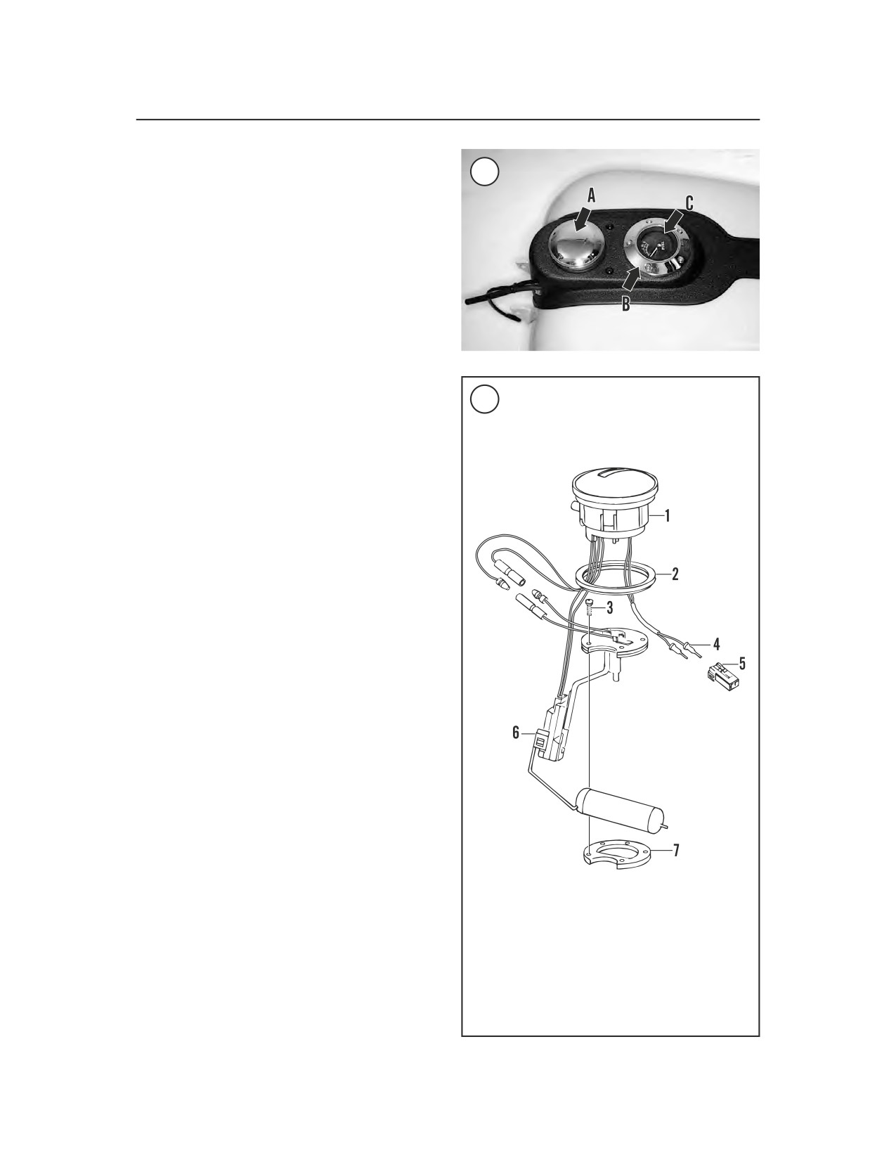
3. Remove the five screws securing the fuel gauge
retainer (B, Figure 100). Remove the retainer.
100
4. Withdraw the fuel gauge (C, Figure 100) from
the sending unit,
5. Remove the five screws and washers securing
the sending unit to the fuel tank.
6. Remove the trim panel ring.
CAUTION
Do not bend the float arm during re-
moval of the sending unit. If bent, the
gauge will give inaccurate readings.
7. Carefully withdraw the sending unit while mov-
ing it back and forth, lifting and turning it in either
101
FUEL GAUGE ASSEMBLY
direction.
(FXDL, FXDWG, FXDP 2001)
8. Remove the gasket from the fuel tank.
9. Install by reversing these removal steps while
noting the following:
a. Lubricate the rubber surface on the base of
the fuel gauge flange with rubbing alcohol or
glass cleaner.
b. Position the electrical terminals in between
the posts on the bottom of the fuel gauge.
c. Align the fuel gauge with the first scribe mark
on the sending unit, then turn it clockwise to
align with the second scribe mark on the
sending unit.
d. Install a new gasket between the sending unit
and fuel tank.
e. Carefully install the sending unit to avoid
damage to the float arm.
f. Tighten all screws securely.
Removal/Installation
(FXDX, FXDWG, FXDP [2001])
Refer to Figure 101.
1. Remove the fuel tank as described in this chap-
ter.
NOTE
The fuel gauge electrical wires are
1.
Fuel gauge
routed through a tube in the fuel tank
2.
Gasket
and are secured with a clamp at the
3.
Screw
bottom of the fuel tank. Loosen the
4.
Pin terminal
clamp and make sure there is enough
5.
Pin housing
6.
Sending unit
slack in the wires to allow the gauge
7.
Gasket
to be pulled up and out of the fuel
tank.