Harley Davidson 2008 Touring Models. Electrical Diagnostics Manual - page 25
HOME
em00195
Stator
[77B] [77A]
[47A] [47B]
2
+
BK
-
BK
1
DC
AC
BK
40 A
MAXIFUSE
B A
Charging System
Ignition
BK
BK
Coil
A B C D
[83A]
Left
Red
Dirty GND
Band
Powertrain
Starter
Battery
Grounds
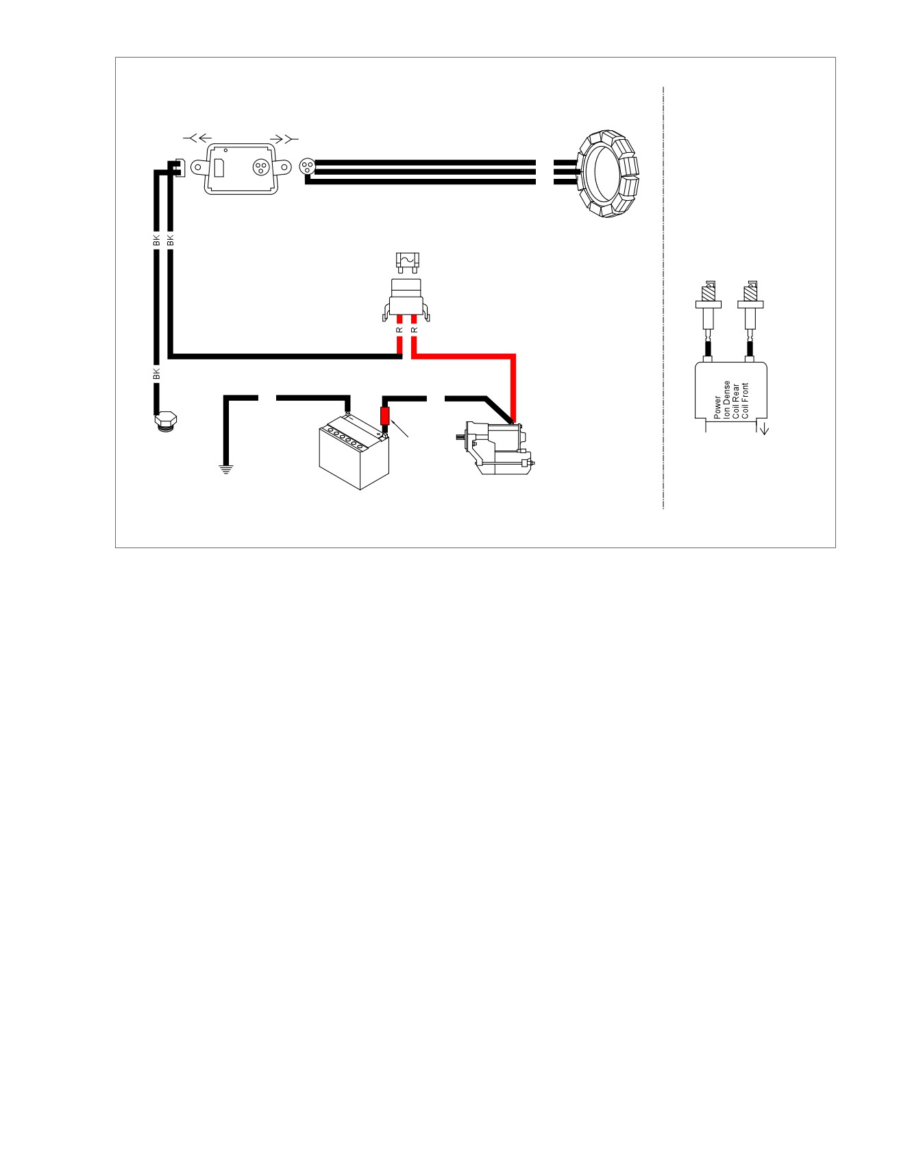
Figure 5-32. Voltage Regulator/Spark Plug Connections
2008 Touring Diagnostics: Audio System 5-91

HOME
Auxiliary Input Audio Distorted: Symptom 6
Turn Auxiliary Device
Volume Down.
Confirm proper operation with no DTCs.
fc00535_en
5-92 2008 Touring Diagnostics: Audio System
HOME
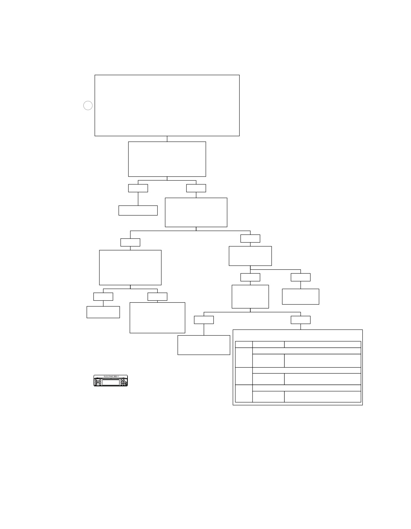
CB Transmitter Inoperative: Symptom 7 (Part 1 of 4)
Perform setup as follows:
Press POWER button to turn radio ON.
Press INT button. Press Softkey 1 to turn Intercom OFF.
Set fairing mounted Headset/Speaker Switch to SPEAKER.
1
Press COM button. Press Softkey 1 to turn CB radio ON.
Set Volume Control to Middle position on horizontal bar graph display.
NOTE:
If CB does not power up or appear on radio display, see INFOTAINMENT
BUS LOST COMMUNICATIONS WITH CB MODULE: DTC U1307.
Depressing Any PTT Switch Will
Change the Radio Display to Reflect
CB Mode and Cause the Transmitter to
Transmit. With PTT Switch Depressed,
Channel Number Will be Inverted.
Are These Your Observations?
YES
NO
Tune Known Good
Receiver to Same
System OK.
Channel Number as
Transmitter. Test Transmitter.
Transmitter OK?
NO
YES
Does Unit Under
Go to CB TRANSMITTER
Test Receiver
INOPERATIVE: Symptom 7
Work OK?
(Part 3 of 4), and Perform
SWR Adjustment Procedures.
Can SWR be
YES
NO
Adjusted to 2:1 or Less?
Does Display
Change When
Replace CB
YES
NO
PTT is
Module.
Depressed?
Go to CB TRANSMITTER
6625
System OK.
INOPERATIVE:
Symptom 7 (Part 4 of 4),
YES
NO
and Perform CB
Antenna Check.
Go to the Appropriate PTT Inoperative Chart.
Go to CB TRANSMITTER
INOPERATIVE:
DTC
DESCRIPTION
GO TO
Symptom 7 (Part 2 of 4).
Handlebar Switches Open
B2009
Handlebar PPT/Squelch Switch Stuck
PTT/Squelch
or Open: DTC B2009 (Part 3 of 3)
Passenger Switches Open
B2012
Passenger Audio/PTT Switch Stuck or
Audio/PTT
Confirm proper operation with no DTCs.
Open: DTC 2012 (Part 1 of 2)
Sidecar Switches Open
B2015
Sidecar Switches Stuck or Open:
PTT/Mode
DTC 2015
fc00536_en
2008 Touring Diagnostics: Audio System 5-93
HOME
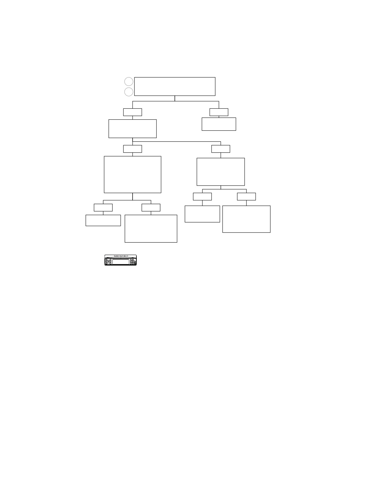
CB Transmitter Inoperative: Symptom 7 (Part 2 of 4)
2
From CB TRANSMITTER
INOPERATIVE: Symptom 7 (Part 1 of 4).
3
Does Lamp Glow When Transmitting?
YES
NO
Replace
Does Lamp Change
CB Module.
in Brilliance While
Speaking?
YES
NO
Go to CB TRANSMITTER
Substitute Known Good
INOPERATIVE: Symptom 7
Microphone. Repeat
(Part 3 of 4),
Test. Does Lamp Glow
and Perform SWR
and Change in Brilliance
Adjustment Procedures.
While Speaking.
Can SWR be Adjusted to
2:1 or Less?
YES
NO
YES
NO
Replace
Go to NO OR LOW
Microphone
AUDIO FROM
Go to CB TRANSMITTER
or Headset.
MICROPHONES:
System OK.
INOPERATIVE:
Symptom 13
Symptom 7 (Part 4 of 4),
(Part 1 of 4).
and Perform CB
Antenna Check.
Confirm proper operation with no DTCs.
fc00537_en
5-94 2008 Touring Diagnostics: Audio System
HOME
9. If SWR is more than 3:1, remove antenna cable from CB
CB Transmitter Inoperative: Symptom 7:
module. Using clip-on test leads, connect one lead of
SWR Adjustment (Part 3 of 4)
ohmmeter to center pin in antenna lead and other lead to
antenna mast. Meter must read 1 ohm or less. Wiggle or
flex mast while observing meter. If resistance is more than
1 ohm or varies when mast is wiggled, replace mast.
Do not press PTT switches with antenna and SWR meter
Inspect connections at base of loading coil and at mounting
disconnected. Transceiver damage could result. (00522b)
bracket. If the SWR is less than 3:1, loosen antenna set
Standing Wave Ratio (SWR) is a technical term for the pro-
screw and change mast length.
cedure that checks how well the CB transmitter and antenna
NOTE
are matched. The SWR should be 2:1 or below on channel 20.
It is normal to observe a reading of less than one ohm between
A SWR of 1:1 is optimum. To check SWR, a SWR meter or
the center conductor and ground due to the configuration of
bridge is required.Your Harley-Davidson dealer will either have
the loading coil.
a SWR meter or direct you to a CB repair shop for a SWR
check. Since the operating procedures for SWR meters vary,
10. Repeat Step 8. If SWR became higher, adjust antenna
be sure you carefully follow the operating instructions for the
mast in opposite direction. Continue adjusting antenna
SWR meter being used.
until the minimum SWR is achieved. If you cannot obtain
an SWR of 2:1 or less by adjusting the antenna length,
1. Locate motorcycle outdoors or in a building with a ceiling
make the mast shorter to improve the SWR. Remove mast
of
11 ft. (3.4 m) minimum above floor. Also, there must
and use grinder to shorten mast (grind in small incre-
be
8 ft. (2.4 m) of radial clearance around motorcycle.
ments). If SWR cannot be adjusted to less than 2:1, see
Adjusting the SWR in an area with a lower ceiling and/or
CB TRANSMITTER INOPERATIVE (Part 4 of 4).
less radial clearance may result in an inaccurate adjust-
ment.
11. After SWR is adjusted on channel 20, check SWR on
channels 1 and 40. Adjust the mast length to obtain a
2. Remove the outer fairing. Obtain Radio Shack SWR Meter
balance between channels 1 and 40.
(Part No.
21-534) or equivalent and SWR METER
ADAPTERS (Part No. HD-48037). Remove the antenna
NOTE
cable and connect the SWR meter to the CB module.
Check the SWR if a luggage rack is installed on the Tour-Pak
Connect the antenna cable to the SWR meter.
cover. Be sure that the Tour-Pak cover is closed when the
check is performed. Accessories mounted on the Tour Pak
3. Check that the antenna loading coil bracket in Tour-Pak
may affect the SWR reading and broadcast range, so the lug-
is tight and that antenna cable is tightly connected to
gage rack should be mounted as far forward as possible. The
loading coil.
Ultra Tour-Pak chrome accent rail also can adversely affect
4. Check that antenna mast is threaded securely on to base
SWR.
and set screw is tight.
5. Before measuring the SWR, the SWR meter must be cal-
ed02069
ibrated. Follow the instructions for the meter being used.
The following procedure is the general calibration most
meter instructions specify.
NOTE
Do not touch the antenna or meter during calibration or SWR
measurement. Move CAL knob and then move your hand away
from meter while calibrating.
6. With ignition and CB switches ON, the SWR meter set on
"FWD", channel 20 selected, press either PTT switches.
Hold the PTT switch and rotate the calibration (CAL) con-
trol until the meter needle aligns with the "CAL" mark.
7. Release the PTT switch and move the FWD/REF switch
to "REF" (reflected).
8. Press and hold either PTT switch. The meter reading is
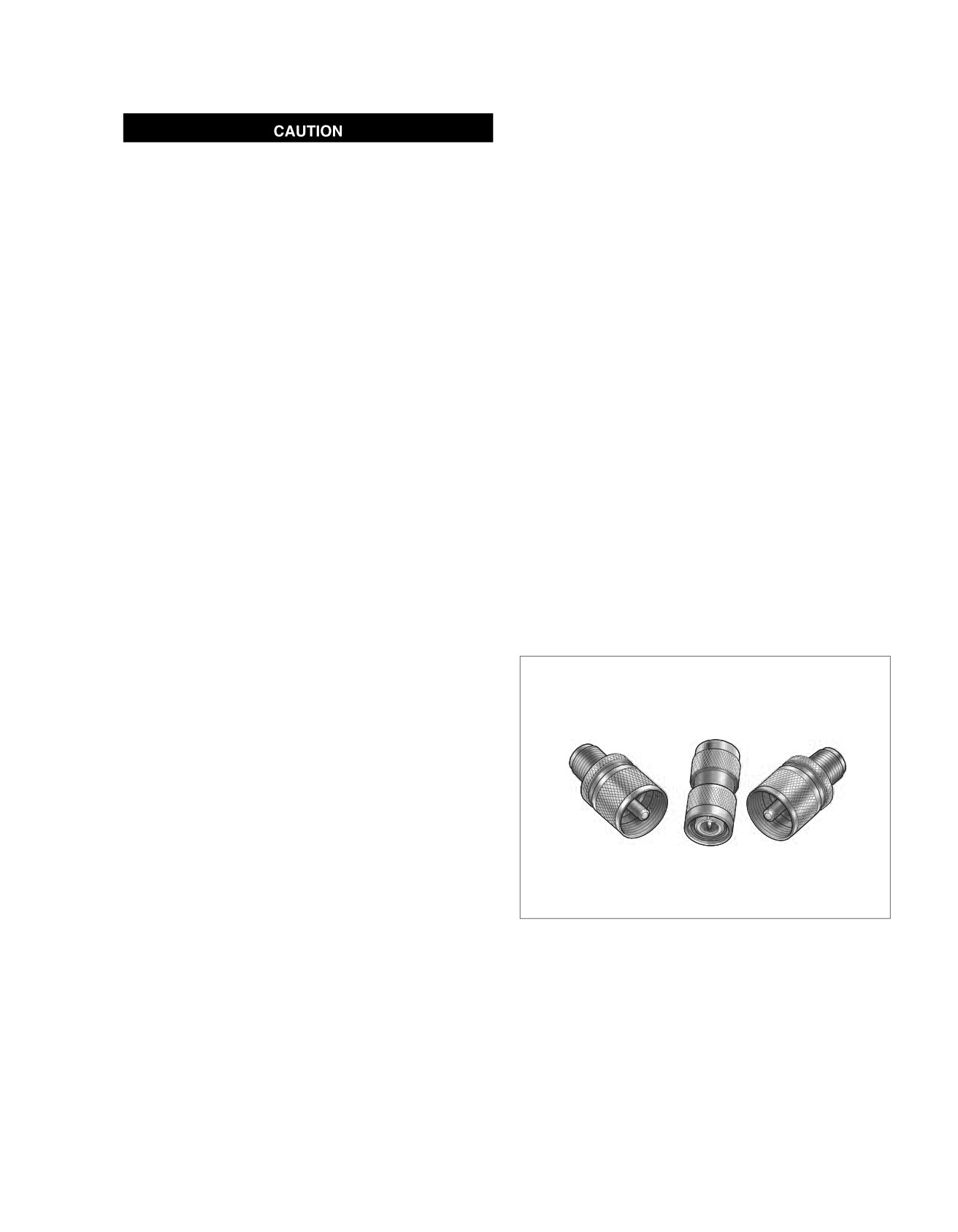
Figure 5-33. SWR Meter Adapters (Part No. HD-48037)
the SWR.
2008 Touring Diagnostics: Audio System 5-95
HOME
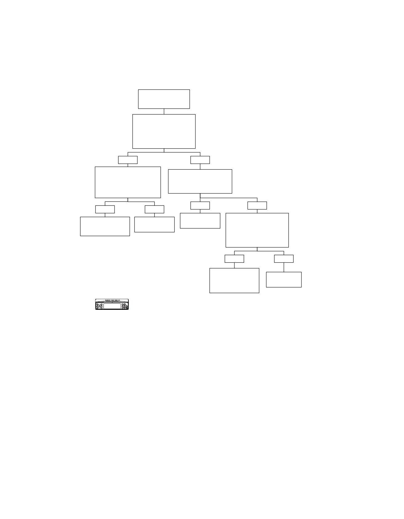
CB Transmitter Inoperative: Symptom 7 (Part 4 of 4)
From CB TRANSMITTER
INOPERATIVE:
Symptom 7 (Part 1 of 4).
Disconnect Antenna Cable at
Back of CB Module. Measure
Continuity From Center Lead
of Cable to Antenna Mast.
Wiggle Mast.
Is Continuity Present?
YES
NO
Disconnect Antenna Cable at
Check Continuity From Center
Loading Coil. Measure Continuity
Lead of Antenna Cable to
Between Center Lead
Cable at Antenna Mast Mount.
and Ground at CB Module.
Is Continuity Present?
Is Continuity Present?
YES
NO
YES
NO
Replace
Disconnect Antenna Cable at
Replace Antenna Cable
Replace
Antenna Mast.
Loading Coil. Check Continuity
Between CB Module
Loading Coil.
From Center Lead of Antenna
and Loading Coil.
6613
Cable to Center Lead of Cable
6618
Leading to Loading Coil.
6609
Is Continuity Present?
YES
NO
Replace Antenna
Cable Between CB
Replace
Module and Loading
Loading Coil.
Coil.
6618
6609
Confirm proper operation with no DTCs.
fc00539_en
5-96 2008 Touring Diagnostics: Audio System
HOME
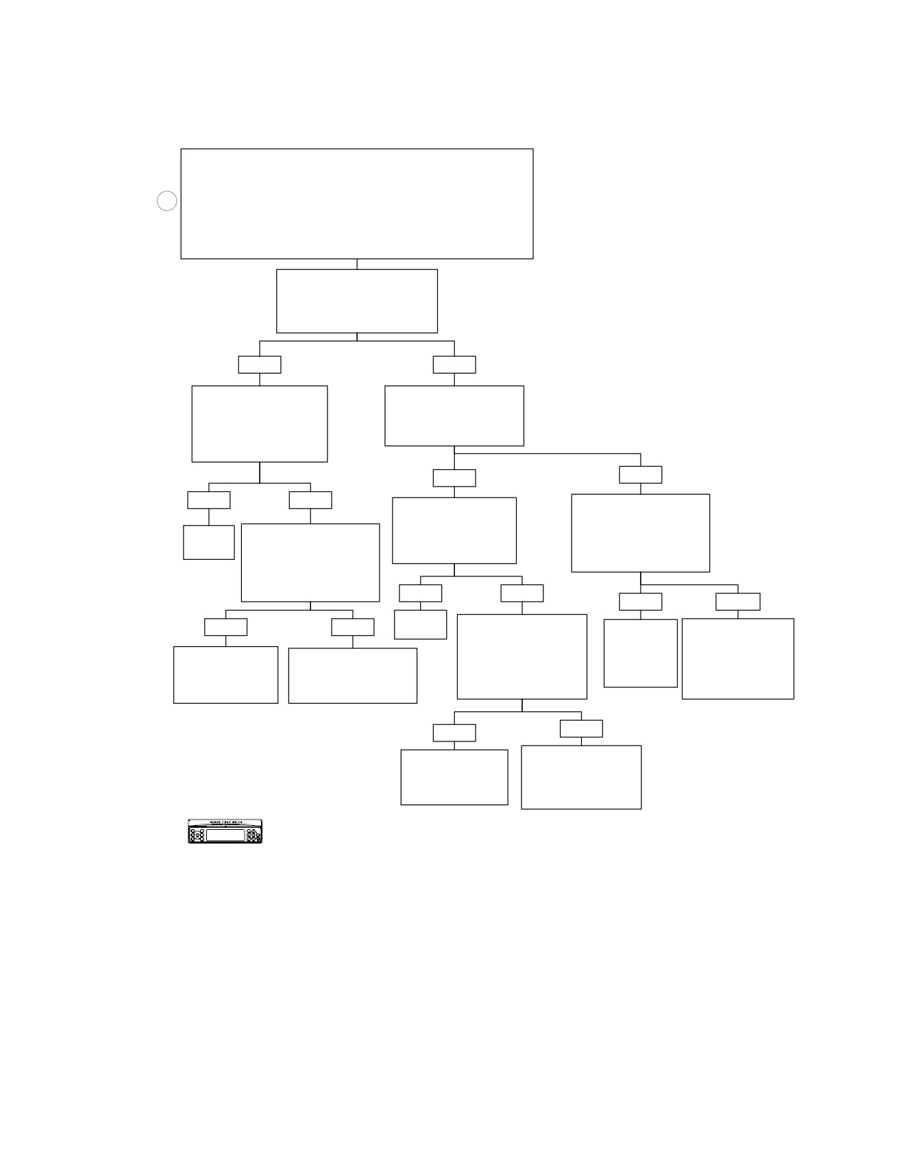
CB Receiver Inoperative: Symptom 8 (Part 1 of 3)
Perform setup as follows:
Press POWER button to turn radio ON.
Press INT button. Press Softkey 1 to turn Intercom OFF.
Set fairing mounted Headset/Speaker Switch to SPEAKER.
1
Press COM button. Press Softkey 1 to turn CB radio ON.
Set Volume Control to Middle position on horizontal bar graph display.
NOTE:
If CB does not power up or appear on radio display, see INFOTAINMENT BUS
LOST COMMUNICATIONS WITH CB MODULE: DTC U1307.
Press SQ- Until Bar Graph Moves to
Left Most Position (Open). This
Forces Squelch Open Independent
of CB Signal Strength.
Is CB Audio Present?
YES
NO
Press SQ+ So Bar Graph
Using External Transmitter
Moves One Bar to the Right.
for Test Signal.
Is Audio Still Present (With
Can CB Audio be Heard When
Test Signal From External
Set to Same Channel as
Transmitter Set to Same
Receiver?
Channel as Receiver)?
YES
NO
YES
NO
Press SQ+ So Bar Graph
Go to CB TRANSMITTER
Moves One Bar to the Right.
INOPERATIVE: Symptom 7
Is Audio Still Present
(Part 3 of 4), and Perform
Receiver
Go to CB TRANSMITTER
(With Test Signal From
SWR Adjustment Procedures.
OK.
INOPERATIVE: Symptom 7
External Transmitter)?
Can SWR be
(Part 3 of 4), and Perform
Adjusted to 2:1 or Less?
SWR Adjustment Procedures.
Can SWR be
Adjusted to 2:1 or Less?
YES
NO
YES
NO
Receiver
Go to CB TRANSMITTER
YES
NO
OK.
Go to CB
Go to CB
INOPERATIVE: Symptom 7
(Part 3 of 4), and Perform
RECEIVER
TRANSMITTER
INOPERATIVE:
INOPERATIVE:
Bad Squelch Circuit
Go to CB TRANSMITTER
SWR Adjustment
Symptom 8
Symptom 7 (Part 4 of 4),
Internal to CB
INOPERATIVE: Symptom 7
Procedures.
(Part 2 of 3).
and Perform CB Antenna
Module. Replace CB
(Part 4 of 4), and Perform CB
Can SWR be
Adjusted to 2:1 or Less?
Check.
Module.
Antenna Check.
6625
NO
YES
Go to CB TRANSMITTER
Bad Squelch Circuit
INOPERATIVE:
Internal to CB
Symptom 7 (Part 4 of 4),
Module. Replace CB
and Perform CB
Module.
Antenna Check.
6625
Confirm proper operation with no DTCs.
fc00540_en
2008 Touring Diagnostics: Audio System 5-97
HOME
em00196
(BK)
[28B]
C.B. Mast ASSY
P/N 76250-98
3
R
Loading Coil ASSY
P/N 76318-98
To
C.B. Antenna
ultra
[50A]
Inside Tour-pak
radio
C.B. Antenna
[28A]
Back Of
C.B. Module
[50D] [50C]
26
BK
[184D]
R
4
4
R
R
4
BK
5
5
BK
BK
5
C.B.
C.B. [184B] [184C]
P/N 70169-06 - P&A non-ultra
harness replaces P/N's
70160-06 & 70164-06 and is
represented when this
connector does not exist.
For all except FLHTCUI
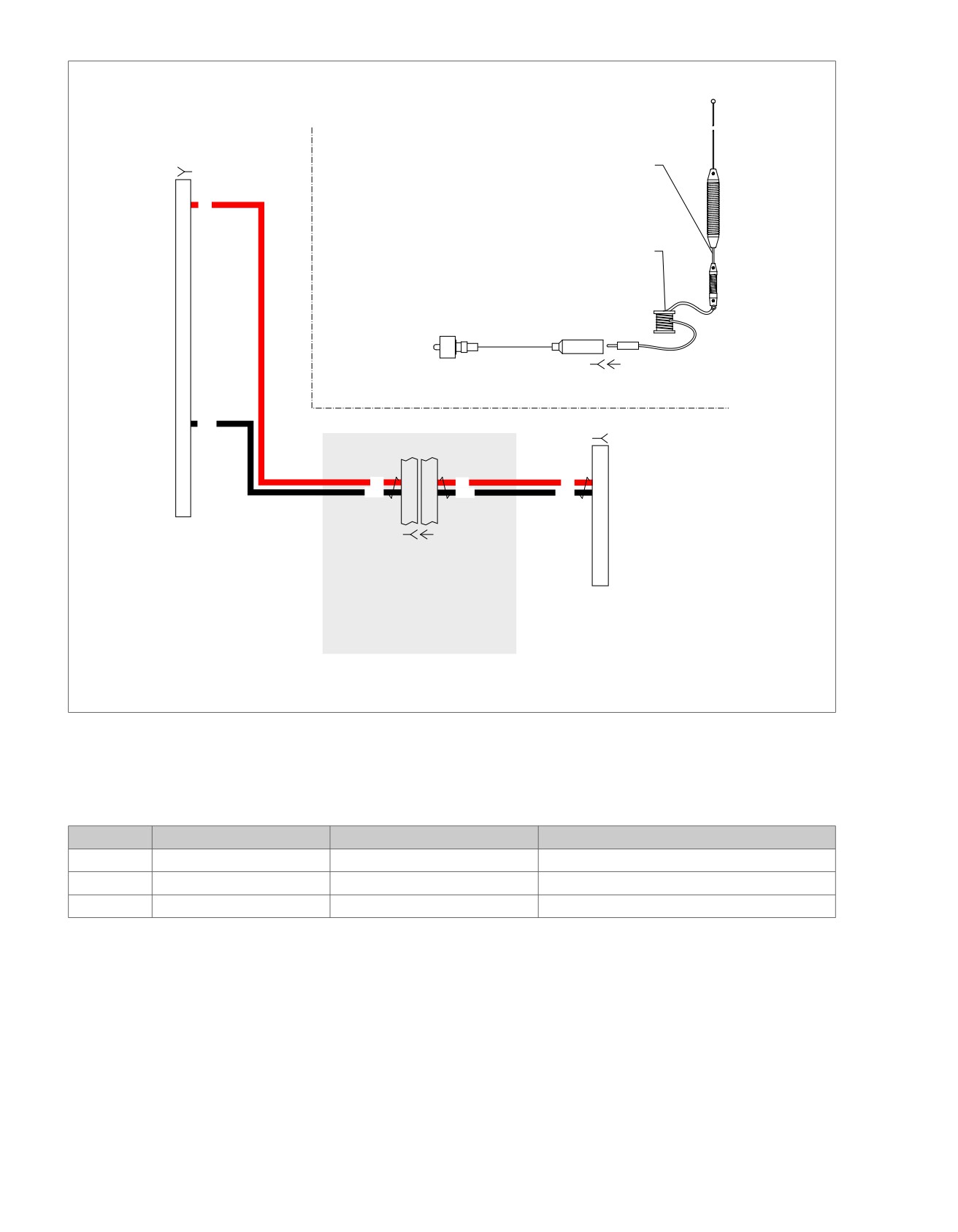
Figure 5-34. CB Receiver Audio Circuit
Table 5-36. FLHT/C/U Wire Harness Connectors
NO.
DESCRIPTION
TYPE
LOCATION
[28]
Radio
35-Place Amp
Inner fairing - back of radio (left side)
[50]
CB antenna cable
-
Inner fairing - back of CB module
[184]
CB module
12-Place Mini-Deutsch
Inner fairing - left side of radio
5-98 2008 Touring Diagnostics: Audio System
HOME
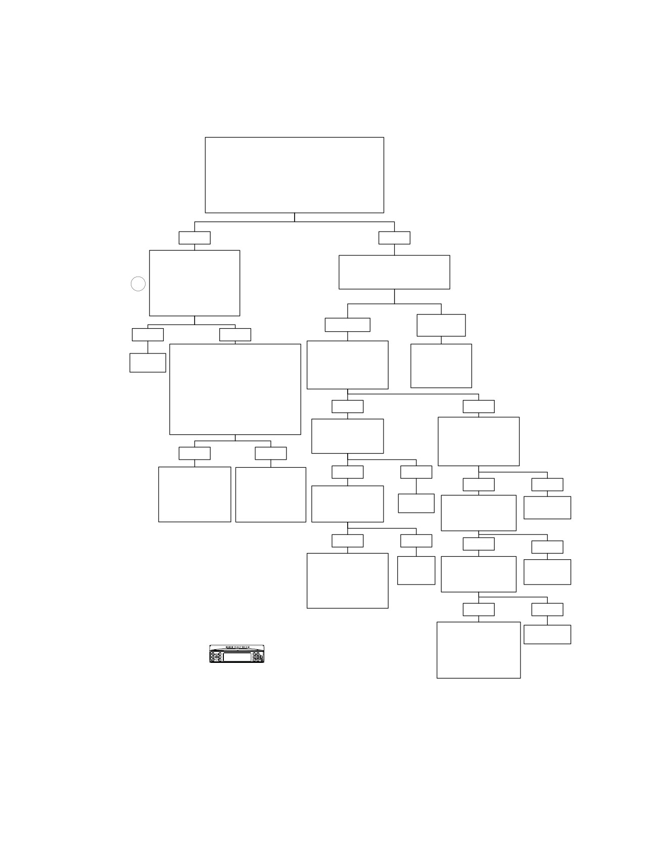
CB Receiver Inoperative: Symptom 8 (Part 2 of 3)
From CB RECEIVER
INOPERATIVE: Symptom 8 (Part 1 of 3).
Install Breakout Box HD-42682 with Adapters HD-45325
Between Connectors [184A] and [184B]. Measure AC
Voltage Between Terminals “4” and “5”. Using External
Transmitter for Test Signal (Both Set to Same Channel
With Squelch Open).
Is Voltage Greater Than 0 VAC and Less Than 1 VAC?
YES
NO
Measure Voltage Between
Measure DC Voltage at Terminals
Terminals 3 and 26 on HD-
“4” and “5” of Breakout
47918 [28].
Box HD-42682.
4
Is 0-1 VAC Present When
Is DC Voltage Present?
Receiving Transmission
From External Transmitter
Set to Same Channel?
Battery
0 Volts
Voltage
YES
NO
Measure Continuity at
Go to CB
Disconnect Connector [28B] from
Terminals “4” and “5” of
RECEIVER
Replace
Radio Leaving Breakout Box Connected
Breakout Box HD-42682.
INOPERATIVE:
Radio.
to Harness. Measure Continuity
Is Continuity (Less Than
Symptom 8
6105
Between Terminal “3” of
2 Ohms) Present?
(Part 3 of 3).
Connector [28B] and Terminal “4”
(R Wire) of Connector [184D], and
also Between Terminal “26” of Connector
YES
NO
[28B] and Terminal “5” (BK Wire of
Connector [184D] on HD-47918 [28].
Disconnect Connector
Measure Continuity to
Is Continuity Present?
[28].
Ground at Terminals “4”
Is Continuity Still
and “5” of Breakout Box
Present?
HD-42682.
YES
NO
Is Continuity Present?
Locate and Repair
YES
NO
Locate and Repair
Short to Ground on
YES
NO
Open on (R) or (BK)
Red Wire Between
Disconnect Connector
Wires From
Connector [184D] at
[184A].
Replace
Disconnect Connector
Connectors [184B/D]
Replace
CB and Connector
Is Continuity Still
Radio.
[28].
and [28B].
CB Module.
[28B] at Radio.
Present?
Is Continuity Still
6105
Present?
6625
6141
6140
YES
NO
YES
NO
Locate and Repair
Replace
Disconnect Connector
Short Between
Replace
CB
[184A].
Terminals “4” (R Wire)
Module.
Is Continuity Still
Radio.
and “5” (BK Wire)
Present?
6625
6105
Between Connectors
[184B/D] and [28B].
YES
NO
6141
Locate and Repair
Replace
Short to Ground on
CB Module.
Terminals “4” (R Wire)
6625
Confirm proper operation with no DTCs.
and “5” (BK Wire)
Between Connectors
[184B/D] and [28B].
6141
fc00541_en
2008 Touring Diagnostics: Audio System 5-99
HOME
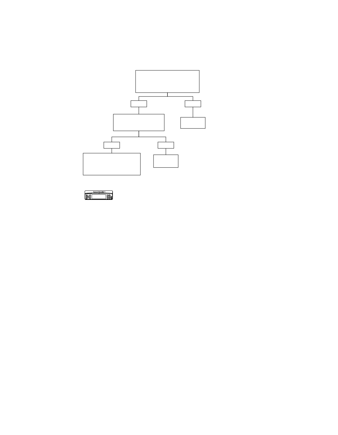
CB Receiver Inoperative: Symptom 8 (Part 3 of 3)
From CB RECEIVER INOPERATIVE:
Symptom 8 (Part 2 of 3).
Disconnect Connector [28].
Is DC Voltage Still Present?
YES
NO
Disconnect Connector
Replace
[184A].
Radio.
Is DC Voltage Still Present?
6105
YES
NO
Locate and Repair Short to Voltage
Replace CB
on Terminals “4” (R) Wire or “5”
Module.
(BK) Wire Between Connectors
[184B/D] and [28B].
6625
6141
Confirm proper operation with no DTCs.
fc00542_en
5-100 2008 Touring Diagnostics: Audio System
HOME
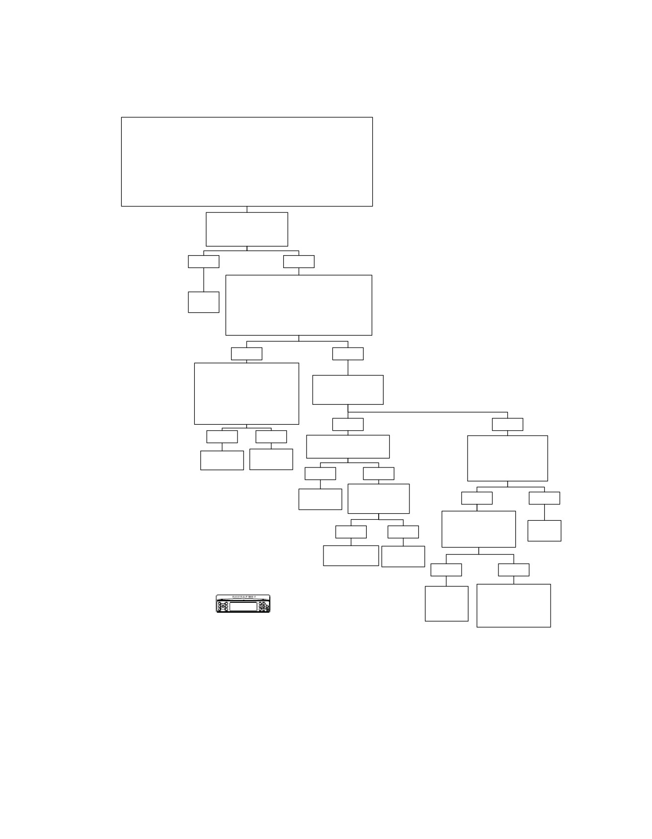
Intercom Inoperative: Symptom 9
Perform setup as follows:
Press POWER button to turn radio ON.
Set fairing mounted Headset/Speaker Switch to HEADSET.
Press COM button. Press Softkey 1 to turn CB radio OFF.
Press INT button. Press Softkey 1 to turn Intercom ON (Setup Mode).
NOTE:
If intercom will not enter setup mode, then intercom is not installed. See Dealer for
assistance. Press Softkey 4 to adjust VOX sensitivity to greater than “10” bars.
Set Front and Rear Intercom Volume Control to Middle position on horizontal bar
graph display.
Speak Into Intercom.
Voice Should be Heard
in All Headsets.
Is it?
YES
NO
Press Softkey 4 So That VOX Level is at
Maximum Value (open). Set Front Volume to
Intercom
Middle Position in Horizontal Bar Graph
OK.
Display. Set Rear Volume to Middle Position.
Is Intercom Audio Present When Speaking Into
Microphone (Rider to Passenger and
Passenger to Rider)?
YES
NO
Adjust VOX Level down 1 step
(13 bars) Using Soft Key 6, so
Is Communication
that VOX level is no longer
Possible In
“open.” Then Test for Audio
Both Directions?
When Speaking Loudly Into
Microphone.
Audio Present?
YES
NO
YES
NO
Replace “Dead” Headset.
Verify Headset Operation
Intercom OK?
on Another Motorcycle.
Intercom
Replace
Do the Speakers and
OK.
Radio.
Microphone Work on
YES
NO
Suspect Headset?
6103
Replace “Dead”
Intercom
Microphone.
YES
NO
OK.
Intercom OK?
Does Suspect
Microphone Work With
Replace
YES
NO
CB on Known Good
Headset.
Vehicle?
Replace
Intercom OK.
Radio.
YES
NO
6103
Replace
Go to NO OR LOW
Radio on
AUDIO FROM
Confirm proper operation with no DTCs.
Effected
MICROPHONES:
Vehicle.
Symptom 13
(Part 1 of 4).
6103
fc00543_en
2008 Touring Diagnostics: Audio System 5-101
HOME
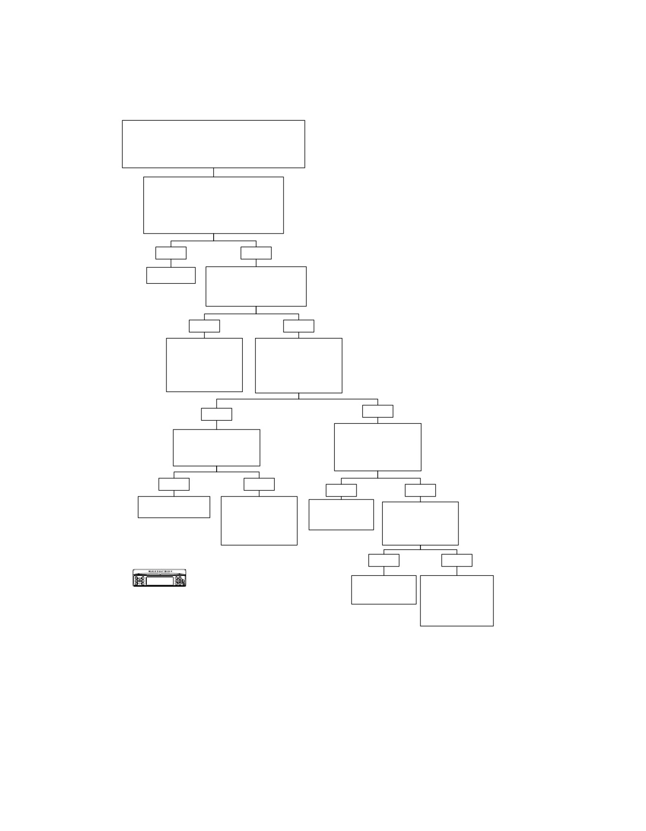
Handheld Microphone/PTT Inoperative: Symptom 10 (Part 1 of 2)
Perform setup as follows:
Press the POWER button to turn the radio ON.
Press INT button. Press Softkey 1 to turn Intercom OFF.
Press COM button. Press Softkey 1 to turn CB radio ON.
Set fairing mounted Headset/Speaker Switch to SPEAKER.
Depressing Handheld PTT Switch Will
Change the Radio Display to Reflect CB
Mode and Cause the Transmitter to Transmit.
With PTT Switch Depressed, Channel
Number Will be Inverted.
Are These Your Observations?
YES
NO
System OK.
Enter Switch Diagnostics.
With Microphone Disconnected,
Does Display Show “Handheld
PTT?”
YES
NO
Go to “SHORT” in
Plug In Handheld
HANDHELD
Microphone.
MICROPHONE/PTT
Does Display Show
INOPERATIVE:
“Handheld PTT” While PTT
Symptom 10
IS NOT Depressed on
(Part 2 of 2).
Microphone?
NO
YES
Depress Microphone
Replace Microphone With
PTT Switch.
Unit Known To Be Good.
Does Display Show
Does New Microphone
“Handheld PTT” When
Work?
Button is Depressed?
YES
NO
YES
NO
Go to “OPEN” in
Handheld Microphone
HANDHELD MICRO-
Handheld
Replace Microphone
PTT Circuit is OK.
PHONE/ PTT
Microphone PTT
With Unit Known To Be
INOPERATIVE:
Circuit is OK.
Good.
Symptom 10
Does New Microphone
(Part 2 of 2).
Work?
YES
NO
Confirm proper operation with no DTCs.
Handheld
Go to “OPEN” in
Microphone PTT
HANDHELD
Circuit is OK.
MICROPHONE/
PTT INOPERATIVE:
Symptom 10
(Part 2 of 2).
fc00544_en
5-102 2008 Touring Diagnostics: Audio System
HOME
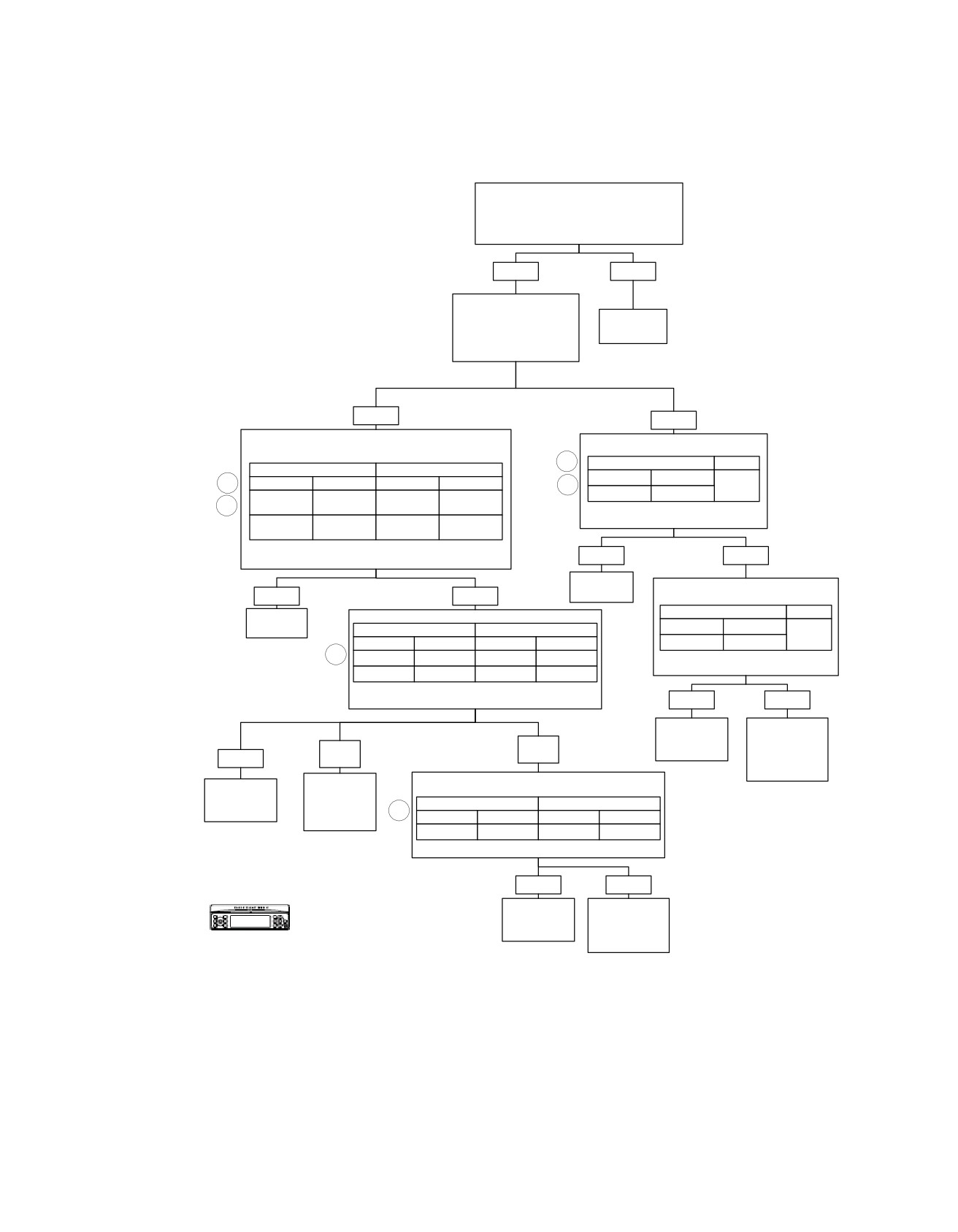
Handheld Microphone/PTT Inoperative: Symptom 10 (Part 2 of 2)
From HANDHELD MICROPHONE/PTT
INOPERATIVE: Symptom 10 (Part 1 of 2).
Use Microphone Known to be Good.
Problem Still Exists?
YES
NO
Place in Diagnostic Mode.
What did Handheld
Replace
Microphone/PTT
Microphone.
Inoperative: Symptom 10
(Part 1 of 2) Indicate?
OPEN
SHORT
Connect Breakout Box to Harness Only.
Check for Continuity as Follows:
Check for Continuity as Follows:
4
FROM
TO
FROM
TO
Connector
Terminal
4
Connector
Terminal
Connector
Terminal
5
Ground
Front
[27B]
“2” (BE/Y)
5
[27B]
“2” (BE/Y)
“7”
Headset DIN
Should Read Infinity.
Front
Does It?
[28B]
“17” (Y/BK)
“6”
Headset DIN
Each Wire Should be Less than 0.5 Ohms.
YES
NO
Is It?
Replace
Disconnect Connector [53]. Check
YES
NO
Radio.
for Continuity as Follows:
6103
FROM
TO
Replace
Check for Continuity as Follows:
Radio.
FROM
TO
Connector
Terminal
Ground
Connector
Terminal
Connector
Terminal
[27B]
“2” (BE/Y)
6103
5
[27B]
“2” (BE/Y)
[53B]
“6”
Should Read Infinity.
[28B]
“17” (Y/BK)
[53B]
“7”
Does It?
Each Wire Should be Less than 0.5 Ohms.
Is It?
YES
NO
Replace Pod
Locate and
Headset
Repair Short to
NO
NO
Harness.
Ground on
YES
(BE/Y)
(Y/BK)
(BK/Y) Wire in
6616
Audio Harness.
Replace Pod
Locate and
Check for Continuity as Follows:
6142
Repair Open
Headset
on (BE/Y) or
FROM
TO
Harness.
5
(Y/BK) Wires.
Connector
Terminal
Connector
Terminal
6616
[27B]
“2” (BE/Y)
[6B]
“4” (BE/Y)
6142
Continuity Present?
YES
NO
Replace Pod
Locate and
Confirm proper operation with no DTCs.
Headset
Repair Open on
Harness.
(BE/Y) Wire in
Audio Harness.
6616
6142
fc00545_en
2008 Touring Diagnostics: Audio System 5-103
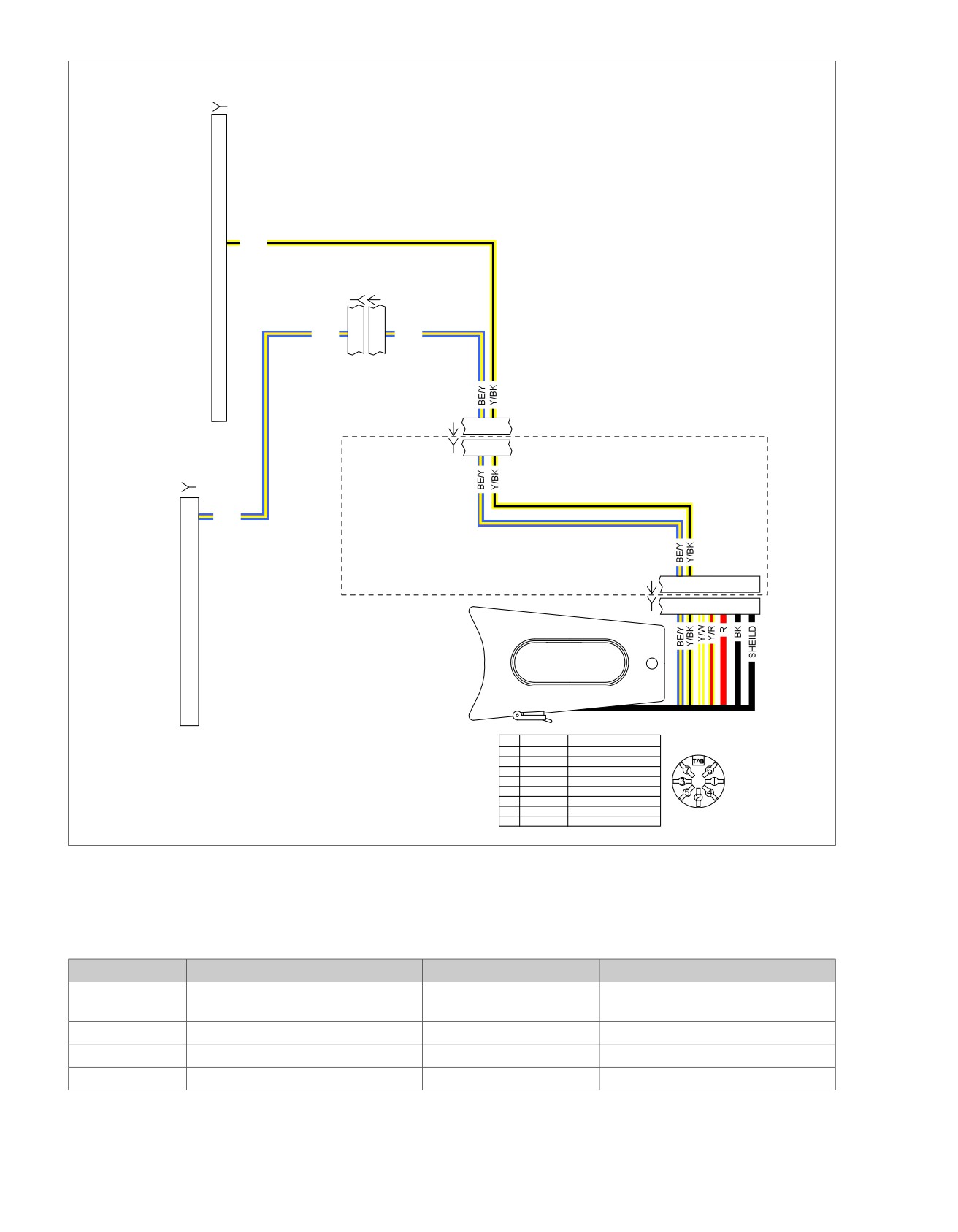
HOME
em00197
(BK)
[28B]
To
ultra
17
Y/BK
radio
[28A]
[6B]
[6A]
BE/Y
2
2
BE/Y
[53A]
6
7
Sidecar Use Only
[53D]
6
7
Ultra
Sidecar
2
BE/Y
Harness
88403-06
To
[53C]
67
radio
[27A]
[53B]
6 7 8 9 10 1112
(BK)
CAV
CIR
DESCRIPTION
DRIVER
1
BK
MIC IN SHARED (-)
HEADSET
2
Y/BK
HDSET SPKR SHARED (-)
3
Y/R
RT FRT HDSET SPKR (+)
4
R
FRT MIC (+)
5
Y/W
LFT FRT HDSET SPKR (+)
6
7
BE/Y
PUSH-TO-TALK
TAB
SHIELD
MIC SHARED SHIELD
Figure 5-35. Handheld Microphone/PTT Circuit
Table 5-37. FLHT/C/U Wire Harness Connectors
NO.
DESCRIPTION
TYPE
LOCATION
[6]
Audio to interconnect harness
6-Place Deutsch (Black)
Inner fairing - back of radio (left side)
Inner fairing - left side of radio
[27]
Radio
23-Place Amp
Inner fairing - back of radio (right side)
[28]
Radio
35-Place Amp
Inner fairing - back of radio (left side)
[53]
Console pod
12-Place Mini-Deutsch
Rear of battery box (under seat)
5-104 2008 Touring Diagnostics: Audio System
HOME
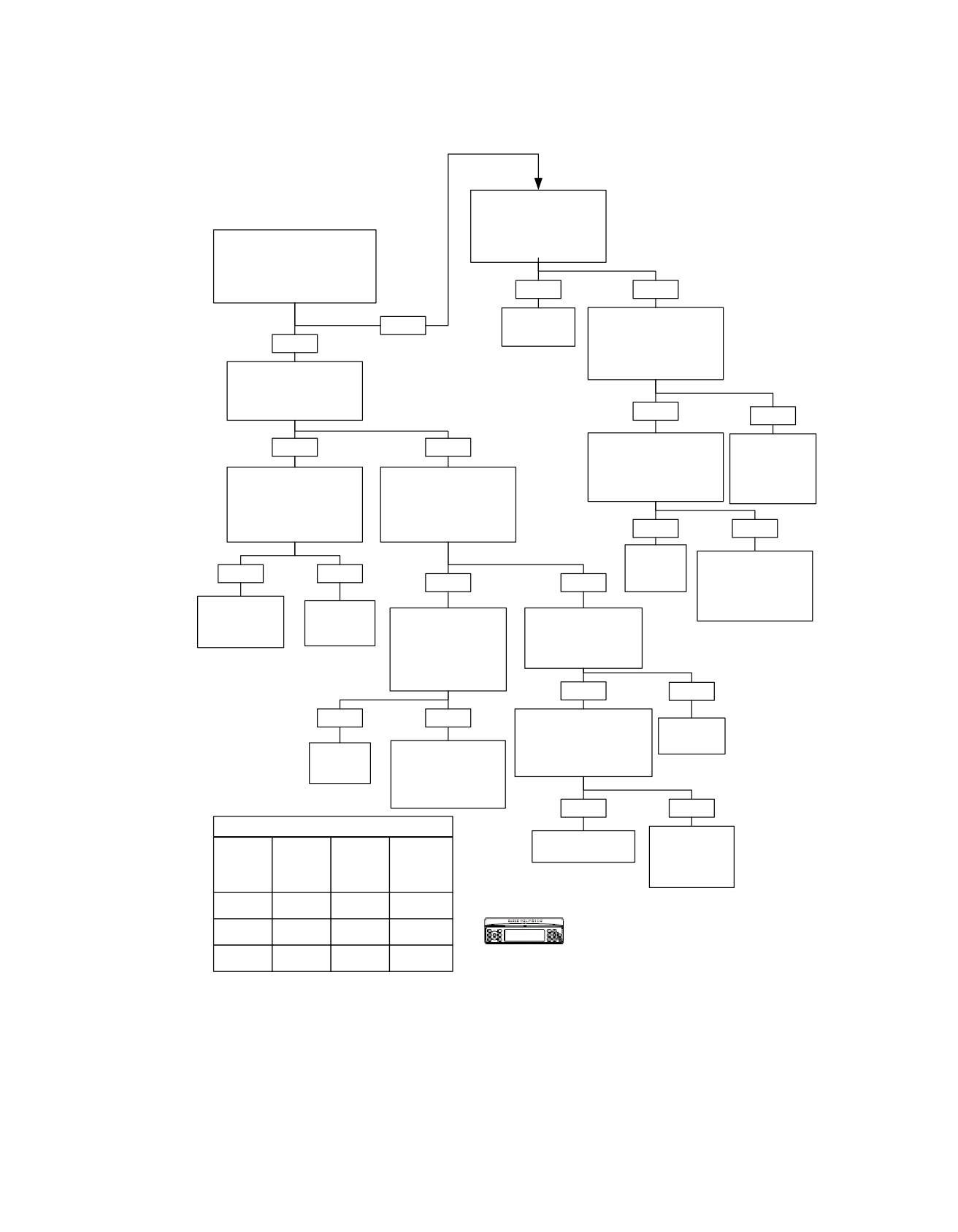
Speaker Switch Malfunction: Symptom 11
Install Breakout Box HD-
47918. Measure Voltage
on Terminal 13 at Breakout
Box [27].
Place Radio in Diagnostic
Is Voltage Less Than 2.5V?
Mode. Place Speaker Switch
in Headset (UP) Position.
Does Display Show SpkA
Only (No SpkB)?
YES
NO
Replace
Measure Continuity
NO
Radio.
Between Terminal “13” at
YES
Breakout Box and Terminal
6103
“12” on Connector [105].
Is Continuity Present?
Place Speaker Switch in
Speaker and Headset
Mode (Middle).
Does Display Show SpkB?
YES
NO
YES
NO
Measure Continuity
Locate and
Between Terminal “13” at
Repair Open
Breakout Box and Terminal
Between Terminal
Place Speaker Switch
Install Breakout Box
“11” on Connector [105].
“12” and
in Speaker Mode
HD-47918. Measure
Is Continuity Present?
Ground.
(Down).
Voltage on Terminal “21”
Does Display Show SpkA
at Breakout Box [27].
and SpkB?
Is Voltage Less Than 2.5V?
YES
NO
Replace
Locate and Repair
Speaker
YES
NO
Open Between Terminal
YES
NO
Switch.
“13” on Connector
[27] and Terminal “11”
6143
Speaker Switch
Replace
on Connector [105].
Measure Voltage on
is OK. Review
Speaker
Measure Continuity
Terminal “13” at
Symptoms List.
Between Terminal
6144
Switch.
Breakout Box [27].
“21” at Breakout Box
6143
and Terminal “10” on
Is Voltage Less Than
2.5V?
Connector [105].
Is Continuity Present?
YES
NO
YES
NO
Measure Continuity
Between Terminal “13” at
Replace
Breakout Box and Ground
Radio.
Replace
Locate and Repair
on Connector [105].
Speaker
Open Between Terminal
6103
Is Continuity Present?
Switch.
“21” on Connector
[27] and Terminal “10”
6143
on Connector [105].
YES
NO
6144
SPEAKER SWITCH FUNCTION TABLE
Locate and
Replace Speaker
Speaker
Speaker
Repair Short
Switch.
Input A
Input B
Diagnostic
Between
Mode
Terminal “13” to
(Terminal
(Terminal
Display
6143
“21”)
“13”)
Ground.
Battery
6145
Headset
0-1 V
SpkA
Voltage
Speaker/
0-1 V
4.5-5.5 V
SpkB
Confirm proper operation with no DTCs.
Headset
Battery
Speaker
4.5-5.5 V
SpkA SpkB
fc00546_en
Voltage
2008 Touring Diagnostics: Audio System 5-105
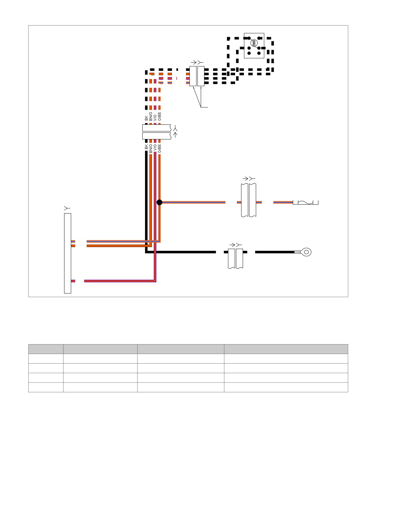
HOME
Speaker
em00198
[105C] [105D]
BK
4
4
BN/O
3
3
V/O
2
2
O/BE
1
1
Connector only on FLTR
121110 9
[105B]
(BK)
121110 9
[105A]
[1A] [1B]
Interconnect Harness
Radio PWR - 15A
O/BE
9
9
O/BE
[27B]
To
radio
12
O/BE
[15A] [15B]
[27A]
13
BN/O
BK
D
D
BK
(BK)
To ground
21
V/O
Figure 5-36. Speaker Switch Circuit
Table 5-38. FLHT/C/U Wire Harness Connectors
NO.
DESCRIPTION
TYPE
LOCATION
[1]
Main
to interconnect harness
16-Place Molex
Inner fairing - right radio support bracket
[15]
Main
to interconnect harness
4-Place Packard
Inner fairing - right fairing bracket
[27]
Radio
23-Place Amp
Inner fairing - back of radio (right side)
[105]
Fairing cap switches
12-Place Multilock
Inner fairing - above upper fork bracket (right side)
5-106 2008 Touring Diagnostics: Audio System
HOME
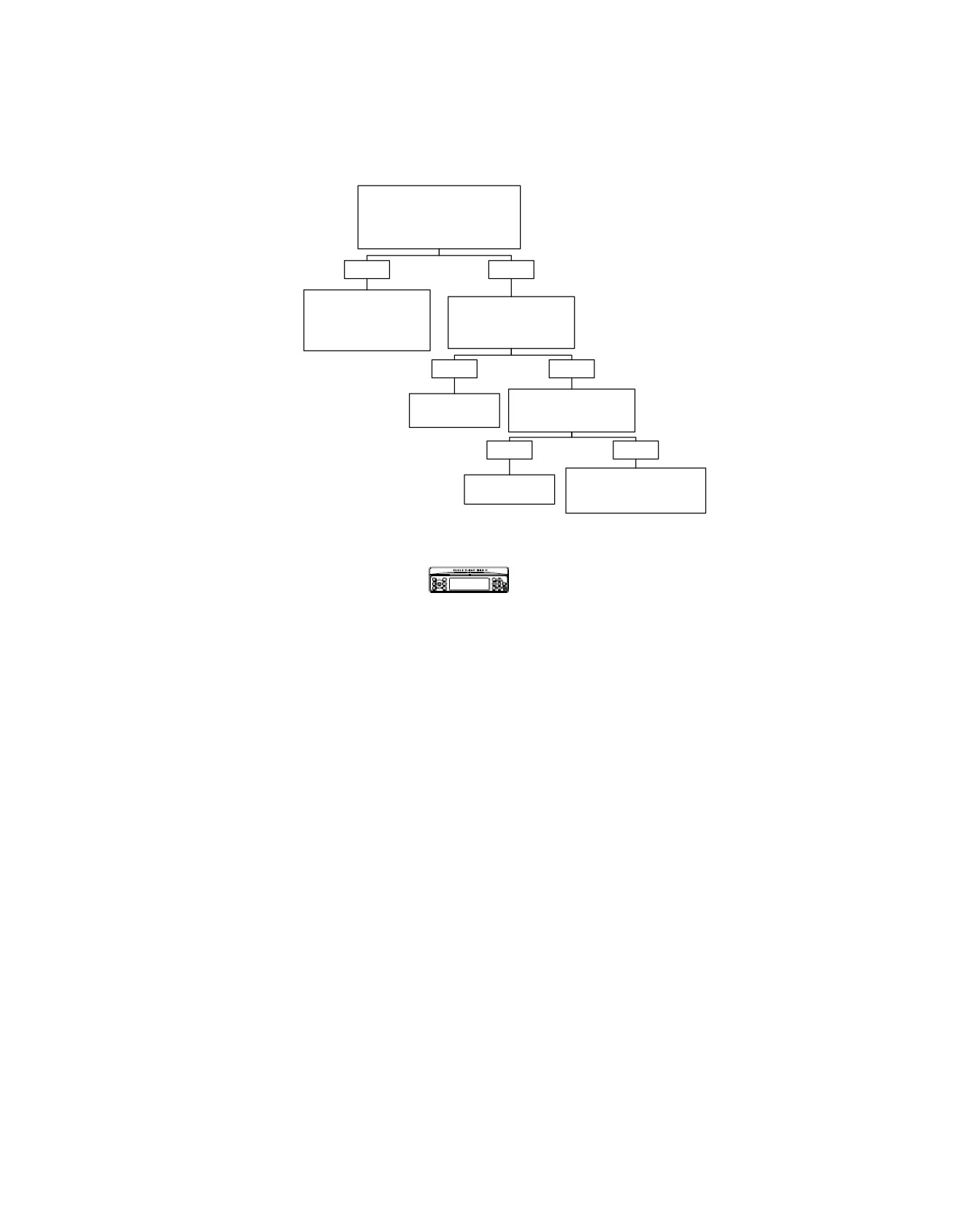
Headset Speakers Inoperative: Symptom 12 (Part 1 of 5)
Connect Headset to Different
Headset Connector on
Motorcycle.
Do Helmet Speakers Work?
YES
NO
Go to HEADSET
Substitute Known Good
SPEAKERS
Coil Cord.
INOPERATIVE: Symptom
Do Helmet Speakers
12
(Part 2 of 5).
Work?
YES
NO
Replace Headset. Do
System
Helmet Speakers
OK.
Work?
YES
NO
Go to HEADSET
System
SPEAKERS INOPERATIVE:
OK.
Symptom 12 (Part 2 of 5).
Confirm proper operation with no DTCs.
fc00547_en
2008 Touring Diagnostics: Audio System 5-107
HOME
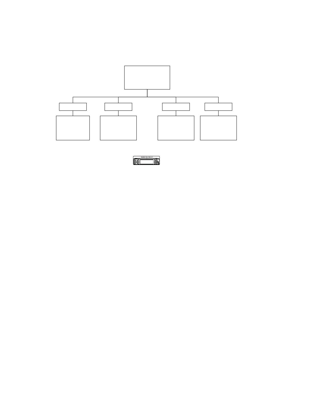
Headset Speakers Inoperative: Symptom 12 (Part 2 of 5)
From HEADSET
SPEAKERS INOPERATIVE:
Symptom 12 (Part 1 of 5).
Which Headset Connector
is Not Working?
All
Rider
Passenger
Sidecar
Go to HEADSET
Go to HEADSET
Go to HEADSET
Go to SPEAKER
SPEAKERS
SPEAKERS
SPEAKERS
SWITCH
INOPERATIVE:
INOPERATIVE:
INOPERATIVE:
MALFUNCTION:
Symptom 12
Symptom 12
Symptom 12
Symptom 11.
(Part 3 of 5).
(Part 4 of 5).
(Part 5 of 5).
Confirm proper operation with no DTCs.
fc00548_en
5-108 2008 Touring Diagnostics: Audio System
HOME
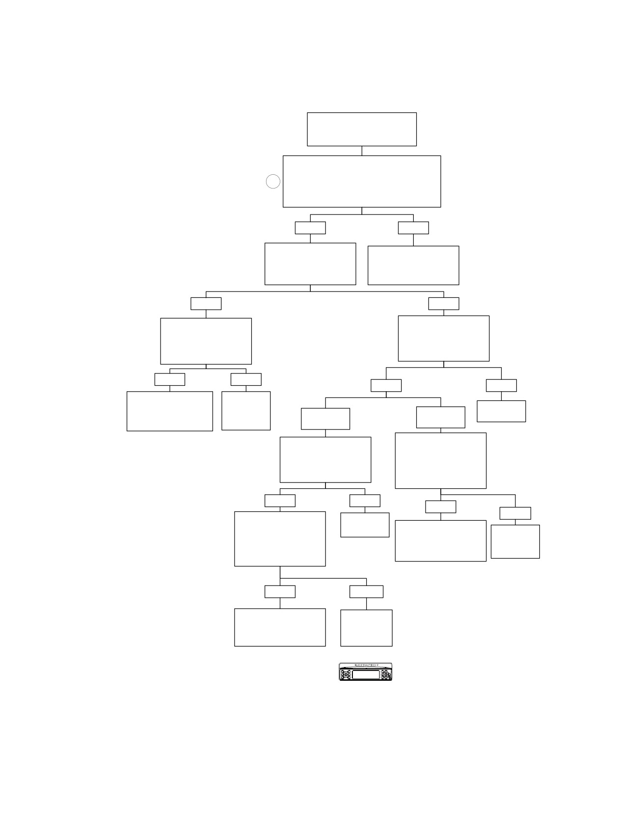
Headset Speakers Inoperative: Symptom 12 (Part 3 of 5)
From HEADSET
SPEAKERS INOPERATIVE:
Symptom 12 (Part 2 of 5).
Measure Continuity Between Terminals:
“17” on HD-47918 [28] to Terminal “2” on Rider
DIN, Terminal “6” on HD-47918 [28] to Terminal “5”
4
on Rider DIN, Terminal “29” on HD-47918 [28] to
Terminal “3” on Rider DIN.
Is Continuity Present?
YES
NO
Measure Continuity
Locate and Repair Open
Between Terminals “17”, “6”
on (Y/R), (Y/W) or (Y/BK)
and “29” on HD-47918 [28].
Wires Between Connector
Is Continuity Present?
[28] and Rider DIN.
NO
YES
Disconnect Connector
Measure Continuity
[53]. Measure Continuity
Between Terminals “17”, “6”
and “29” on HD-47918 [28]
Between Terminals “17”, “6”
and Ground.
and “29” on HD-47918 [28].
Is Continuity Present?
Is Continuity Still Present?
YES
NO
YES
NO
Locate and Repair Short
Replace
on (Y/R), (Y/W) or (Y/BK)
Rider
Replace
Wires Between Connectors
Headset
Terminal “17”
Terminals “6”
Radio.
[53B] and [28B].
Connector.
Only.
or “29”.
6103
6616
6148
Disconnect Connector
Measure Voltage Between
[53]. Measure Continuity
Terminals “6” and “29” on
Between Terminals “6” and
HD-47918 [28] and Ground.
“29” on HD-47918 [28] to
Is Voltage Greater Than 9 V
Ground.
Present?
Is Continuity Still Present?
YES
NO
YES
NO
Disconnect Connector
Replace
[53]. Measure Voltage on
Radio.
Locate and Repair Short
Replace
Terminals “6” and “29” on
to Ground on (Y/R) or (Y/W)
Rider
HD-47918 [28] to Ground.
6103
Wires Between Connectors
Headset
Is Voltage Greater Than 9V
[53B] and [28B].
Connector.
Present?
6616
6147
YES
NO
Locate and Repair Short
Replace
to Voltage on (Y/R) or (Y/W)
Rider
Wires Between Connectors
Headset
[53B] and [28B].
Connector.
6147
6616
Confirm proper operation with no DTCs.
fc00549_en
2008 Touring Diagnostics: Audio System 5-109
HOME
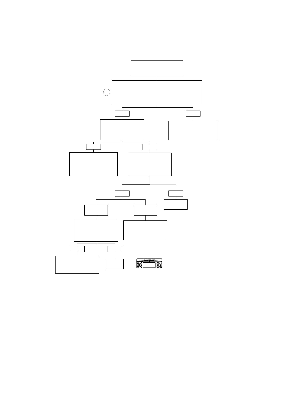
Headset Speakers Inoperative: Symptom 12 (Part 4 of 5)
From HEADSET
SPEAKERS INOPERATIVE:
Symptom 12 (Part 2 of 5).
Measure Continuity Between Terminals:
“17” on HD-47918 [28] to Terminal “2” on Passenger DIN,
4
“5” on HD-47918 [28] to Terminal “5” on Passenger DIN,
“28” on HD-47918 [28] to Terminal “3” on Passenger DIN.
Is Continuity Present?
YES
NO
Measure Continuity
Locate and Repair Open
Between Terminals “17”, “28”
Between (GY/Y), (GY/O) and (Y/
and “5” on HD-47918 [28].
BK) Wires on Connector [28] and
Is Continuity Present?
Passenger DIN.
6149
YES
NO
Locate and Repair Short
Measure Continuity
Between (GY/Y), (GY/O) and
Between Terminals “17”, “28”
(Y/BK) Wires Between
and “5” on HD-47918 [28]
Connector [28B] and Passenger
and Ground.
DIN.
Is Continuity Present?
6150
YES
NO
Replace
Radio.
Terminal “17”
Terminals
Only.
“28” or “5”
6103
Measure Voltage Between
Locate and Repair Short to
Terminals “28” and “5” on
Ground on (GY/Y) or (GY/O)
HD-47918 [28] and Ground.
Wires Between Connector
Is Voltage Greater Than 9 V
[28B] and Passenger DIN.
Present?
6150
YES
NO
Locate and Repair Short to
Voltage on (GY/Y) or (GY/O)
Replace
Confirm proper operation with no DTCs.
Wires Between Connector
Radio.
[28B] and Passenger DIN.
fc00550_en
6103
6150
5-110 2008 Touring Diagnostics: Audio System