Harley Davidson 2008 Touring Models. Electrical Diagnostics Manual - page 23
HOME
em00185
For All
Except
FLHTCU
[41A]
[41D]
[41C] [41B]
(BK)
[28B]
GN
5
5
5
5
GN
LGN/BN
6
6
6
6
LGN/BN
1
GN
2
BN
[36A]
[36B]
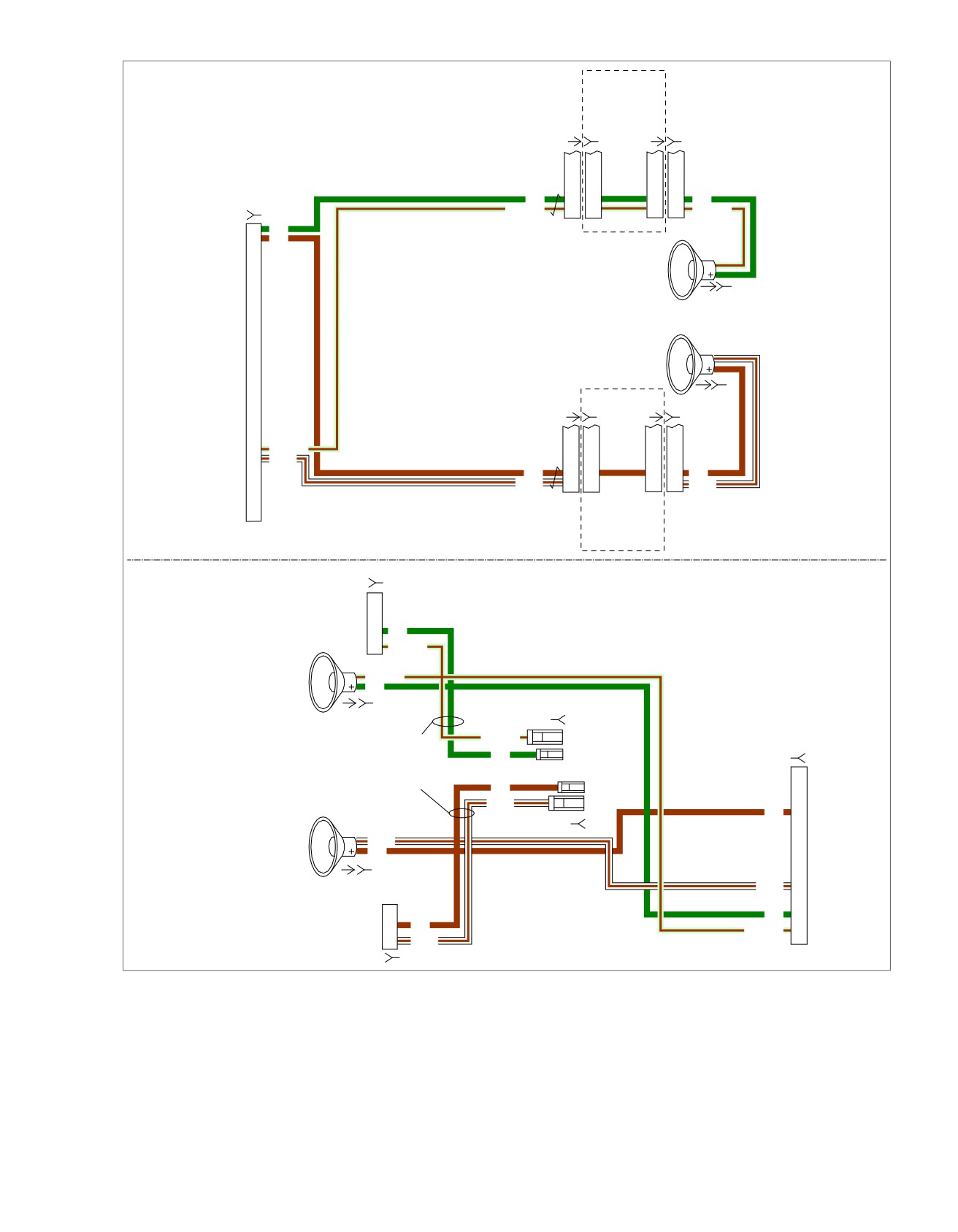
Rear Speakers Without Amplifier
[37A]
To
ultra
(BK)
radio
[37B]
[42A]
[42D]
[42C]
[42B]
(BK)
[28A]
24
LGN/BN
25
W/BN
BN
5
5
5
5
BN
W/BN
6
6
6
6
W/BN
For All
Except
FLHTCU
[41B]
5
GN
6
LGN/BN
Rear Speakers With Amplifier
LGN/BN
GN
[36A] [36D]
[36B]
With Amplifier And No Sidecar
LGN/BN
These Leads Are Not Active
GN
[149B]
From The Radio And Should
Be Secured Inside The Speaker
Pods With No Connection
BN
W/BN
BN
8
[37B]
W/BN
BN
[37A] [37D]
W/BN
15
GN
22
5
BN
LGN/BN
23
6
W/BN
[42B]
Figure 5-22. Rear Speaker Circuit
2008 Touring Diagnostics: Audio System 5-51

HOME
Table 5-24. Wire Harness Connectors
NO.
DESCRIPTION
TYPE
LOCATION
[28]
Radio
35-Place Amp
Inner fairing - back of radio (left side)
[36]
Rear right speaker
Spade Contacts
Inside rear right speaker box
[37]
Rear left speaker
Spade Contacts
Inside rear left speaker box
[41]
Rear right speaker/passenger controls
6-Place Mini-Deutsch
Inside rear right speaker box
[42]
Rear left speaker/passenger controls
6-Place Mini-Deutsch
Inside rear left speaker box
[149]
High output amplifier
23-Place Amp
Under luggage rack (right side)
5-52 2008 Touring Diagnostics: Audio System
HOME
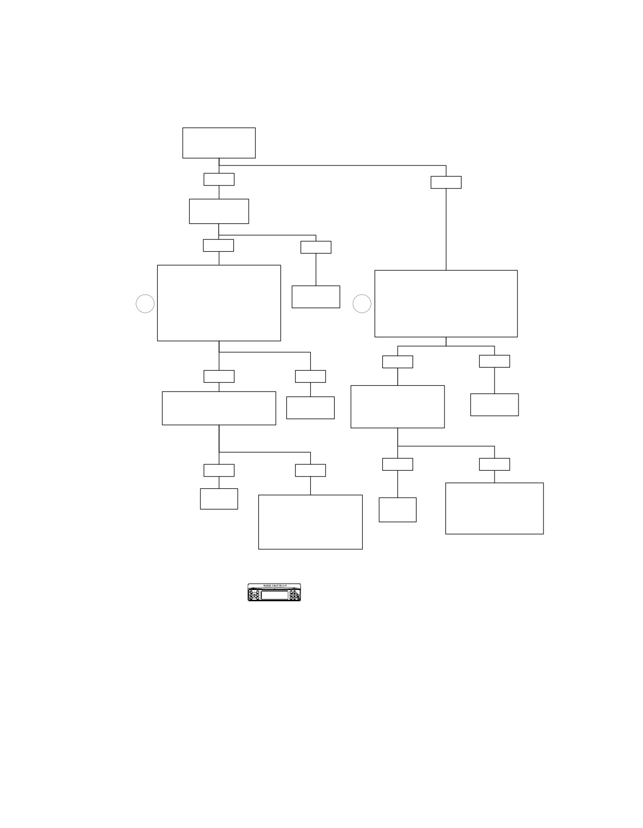
Rear Speakers Open: DTC B2021
Is Optional Harley-
Davidson Amplifier
Installed?
YES
NO
Inspect amplifier
fuse.
Is fuse good?
YES
NO
Disconnect Connector [149].
Install Breakout Box HD-47918 to
Disconnect Connector [28]. Install Breakout
Amplifier Harness Leaving Amplifier
Box HD-47918 Leaving Radio Disconnected.
Disconnected. Measure Resistance
Replace
Measure Resistance
1
Between Terminals “22” and “23” (Left
amplifier fuse.
1
Between Terminals “2” and “25” (Left
Speaker) or Between Terminals
Speaker) or Between Terminals “1” and “24”
6130
“8” and “15” (Right Speaker)
(Right Speaker) on Breakout Box.
on Breakout Box.
Is Resistance Greater Than 3 Ohms?
Is Resistance Greater Than 3 Ohms?
YES
NO
YES
NO
Measure Resistance Across
Measure Resistance
Across Speaker Terminals.
Replace
Speaker Terminals.
Replace
Is Resistance
Radio.
Is Resistance Greater Than 3
Amplifier.
Ohms?
Greater Than 3 Ohms?
6101
6107
YES
NO
YES
NO
On Harness From Radio to
Replace
Speaker, Locate and Repair
Speaker.
On Harness From Amplifier to
Replace
Open Between Terminal “2” or
Speaker, Locate and Repair
6606
Speaker.
“25” and Left Speaker, or
Open Between Terminal “22” or
Between Terminal “1” or “24”
“23” and Left Speaker, or
6606
and Right Speaker.
Between Terminal “8” or “15” and
Right Speaker.
6561
6117
Verify DTC is no longer present using radio
diagnostics. See RADIO DIAGNOSTICS. Confirm
fc00513_en
proper operation with no DTCs.
2008 Touring Diagnostics: Audio System 5-53
HOME
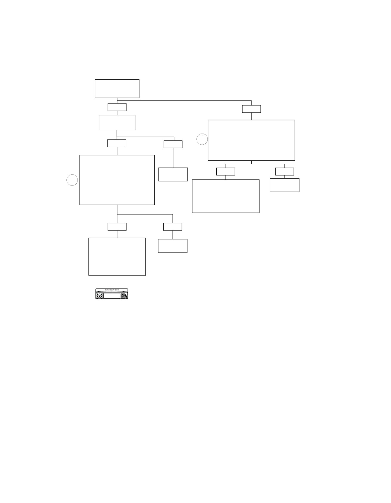
Rear Speakers Shorted to Ground: B2022
Is Optional Harley-
Davidson Amplifier
Installed?
YES
NO
Inspect amplifier
fuse.
Disconnect Connector [28]. Install
Is fuse good?
Breakout Box HD-47918 Leaving Radio
Disconnected. Measure Continuity to
1
Ground Between Terminal “2” or “25” (Left
YES
Speaker) and Ground, or Between Terminal
NO
“1” or “24” (Right Speaker) and Ground on
Breakout Box.
Is Continuity Present?
Disconnect Connector [149]. Install
Breakout Box HD-47918 to Amplifier
Harness Leaving Amplifier
Replace
YES
NO
Disconnected. Measure Continuity to
amplifier fuse.
1
Ground Between Terminals “22” or
On Harness From Radio Connector
Replace
“23” (Left Speaker) and Ground, or
6130
[28] to Speaker, Locate
Radio.
Between Terminals “8” or “15” (Right
Speaker) and Ground on Breakout Box.
and Repair Short to Ground
6101
Is Continuity Present?
Between Terminal “2” or “25” and
Left Speaker, or Between Terminal
“1” or “24” and Right Speaker.
6560
YES
NO
On Harness From Amplifier
Replace
Connector [149] to Speaker,
Amplifier.
Locate and Repair Short to
Ground Between Terminal
6107
“22” or “23” and Left Speaker,
or Between Terminal “8” or
“15” and Right Speaker.
6116
Verify DTC is no longer present using radio
diagnostics. See RADIO DIAGNOSTICS. Confirm
proper operation with no DTCs.
fc00514_en
5-54 2008 Touring Diagnostics: Audio System
HOME
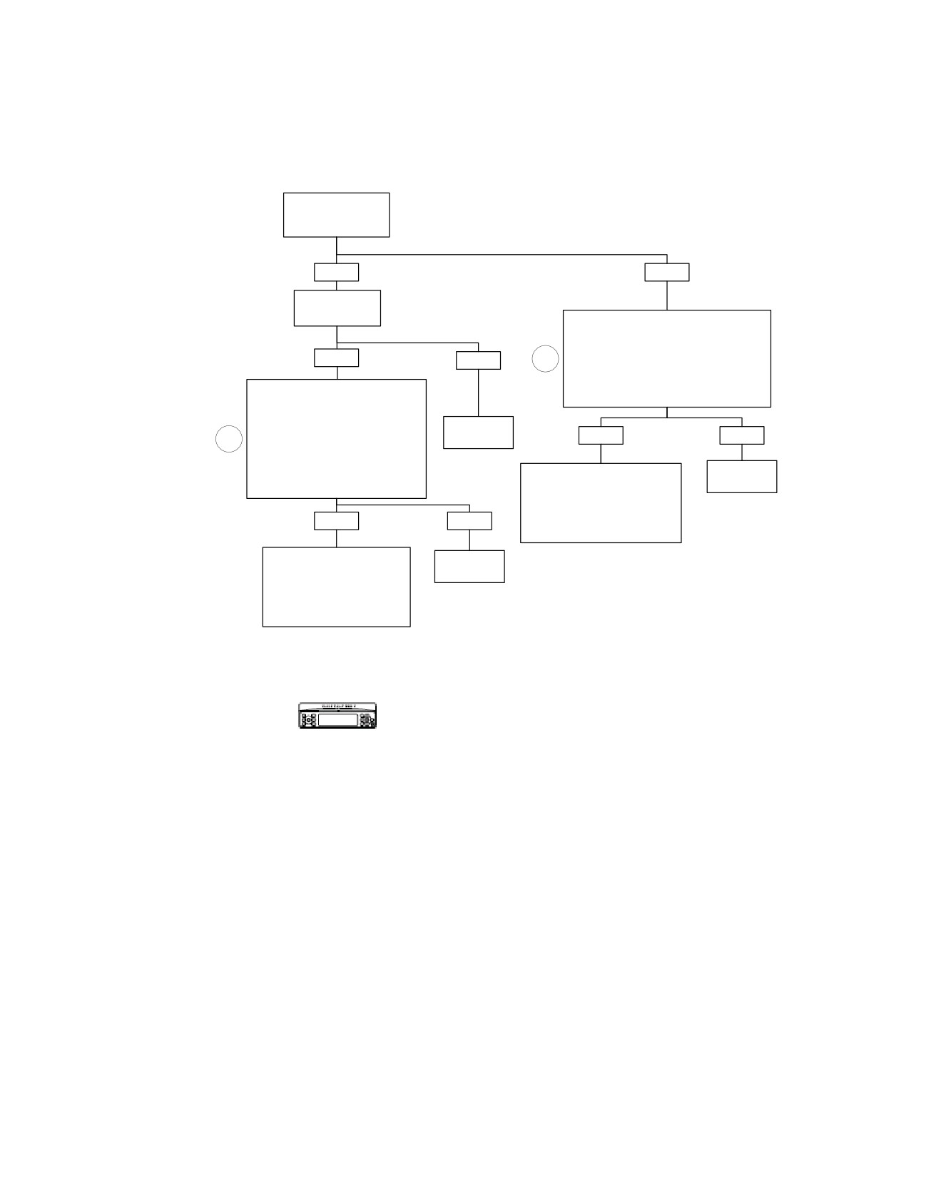
Rear Speakers Shorted to Battery: DTC B2023
Is Optional Harley-
Davidson Amplifier
Installed?
YES
NO
Inspect amplifier
fuse.
Is fuse good?
Disconnect Connector [28]. Install Breakout
Box HD-47918. Turn Ignition ON.
Measure Voltage Between Terminal “2” or
YES
NO
1
“25” (Left Speaker) and Ground, or
Between Terminal “1” or “24” (Right
Speaker) and Ground on Breakout Box.
Disconnect Connector [149]. Install
Is Voltage Present?
Breakout Box HD-47918 to Amplifier
Harness Leaving Amplifier
Disconnected. Turn Ignition ON.
Replace
Measure Voltage Between Terminal
YES
NO
1
amplifier fuse.
“22” or “23” (Left Speaker) and
Ground, or Between Terminal “8” or
6130
“15” (Right Speaker) and Ground on
Replace
Disconnect Speaker. Locate
Breakout Box.
Radio.
and Repair Short to Voltage on
Is Voltage Present?
Terminals “2” (BN) or “25” (W/BN)
6101
for Left Speaker, or Terminals
YES
NO
“1” (GN) or “24” (LGN/BN) for
Right Speaker.
6560
Disconnect Speaker. Locate
Replace
and Repair Short to Voltage on
Amplifier.
Terminals “8” (BN) or “15” (W/
BN) for Left Speaker, or
6107
Terminals “22” (GN) or “23”
(LGN/BN) for Right Speaker.
6117
Verify DTC is no longer present using radio
diagnostics. See RADIO DIAGNOSTICS. Confirm
fc00515_en
proper operation with no DTCs.
2008 Touring Diagnostics: Audio System 5-55
HOME
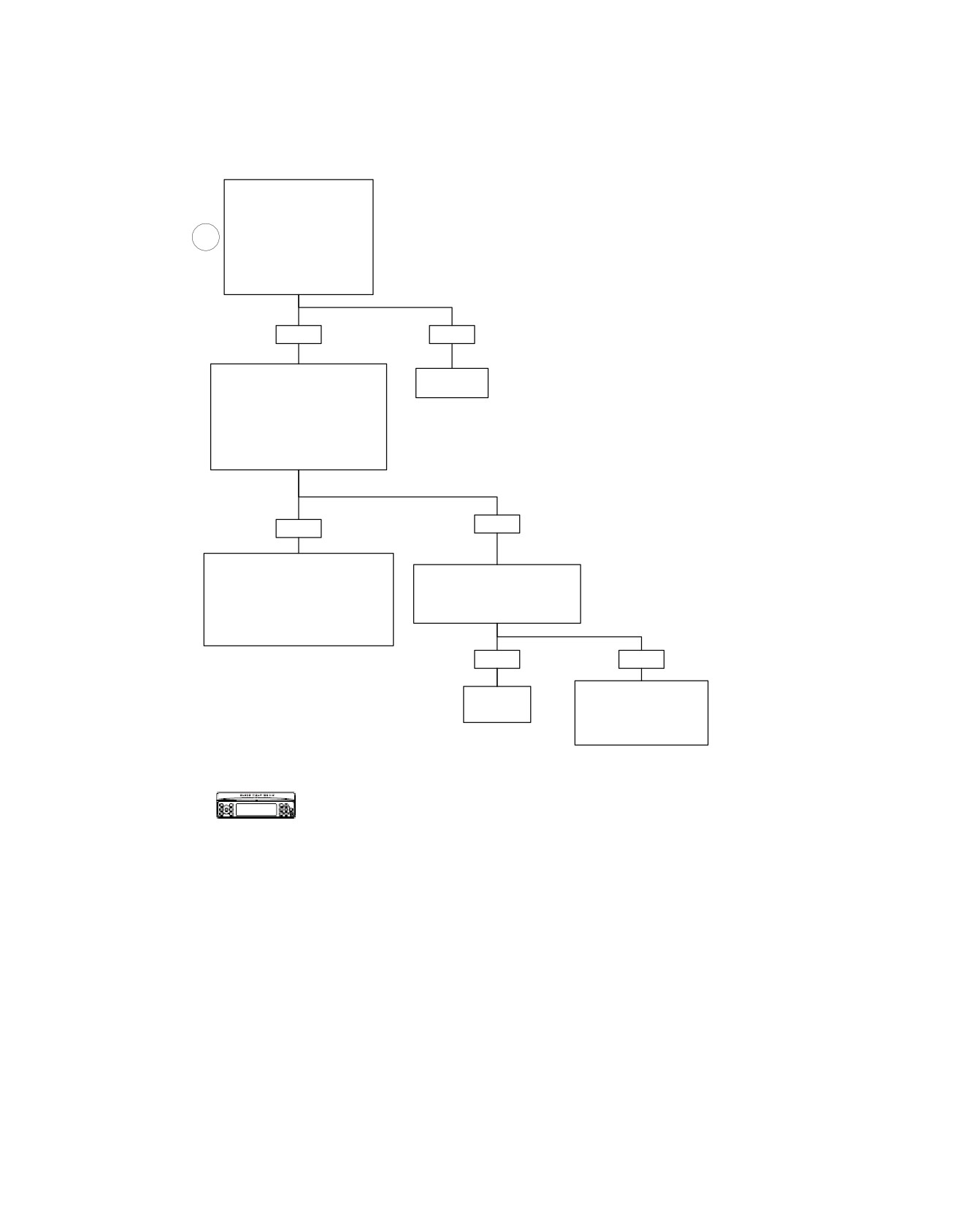
Sidecar Speakers Shorted: DTC B2024
Disconnect Connector [28].
Install Breakout Box HD-47918.
Measure Resistance Between
Terminals “2” and “25” (Left
1
Speaker) or Between Terminals
“1” and “24” (Right Speaker)
on Breakout Box.
Is Resistance Less Than One
Ohm?
YES
NO
Disconnect Sidecar Speaker at
Replace
Connector [37] (Left) or Connector
Radio.
[36] (Right). Measure Resistance
Between Terminals “2” and “25” (Left
6101
Speaker) or Between Terminals “1”
and “24” (Right Speaker) on
Connector [28].
Is Resistance Less Than One Ohm?
NO
YES
Locate and Repair Short
Between Terminals “2” and “25”
Disconnect Sidecar Speaker.
(Left Speaker) or Between Terminals
Measure Resistance of Sidecar
“1” and “24” (Right Speaker)
Speaker at Speaker Terminals.
on Harness From Connector
Is Resistance Less Than One Ohm?
[28] to Connector [37] (Left) or
Connector [36] (Right).
YES
NO
6118
Replace
Locate and Repair Short
Speaker.
Between Sidecar Speaker
and Connector [37] (Left) or
6943
Connector [36] (Right).
6971
Verify DTC is no longer present using radio
diagnostics. See RADIO DIAGNOSTICS.
fc00516_en
Confirm proper operation with no DTCs.
5-56 2008 Touring Diagnostics: Audio System
HOME
em00186
[41A]
[41D]
[41C]
[41B]
(BK)
(BK)
[28B]
1
GN
GN
5
5
5
5
GN
2
BN
LGN/BN
6
6
6
6
LGN/BN
[36B] [36E]
With Amplifier And No Sidecar
LGN/BN
LGN/BN
These Leads Are Not Active
GN
GN
From The Radio And Should
Be Secured Inside The Speaker
To
Pods With No Connection
BN
BN
ultra
W/BN
W/BN
radio
[28A]
[37B] [37E]
24
LGN/BN
25
W/BN
[42A]
[42D]
[42C]
[42B]
(BK)
BN
5
5
5
5
BN
W/BN
6
6
6
6
W/BN
LGN/BN
GN
Right
Sidecar
Speaker
W/BN
[197B] [197A]
BN
GN
1
1
GN
Left
LGN/BN
2
2
LGN/BN
Sidecar
Speaker
BN
5
5
BN
W/BN
6
6
W/BN
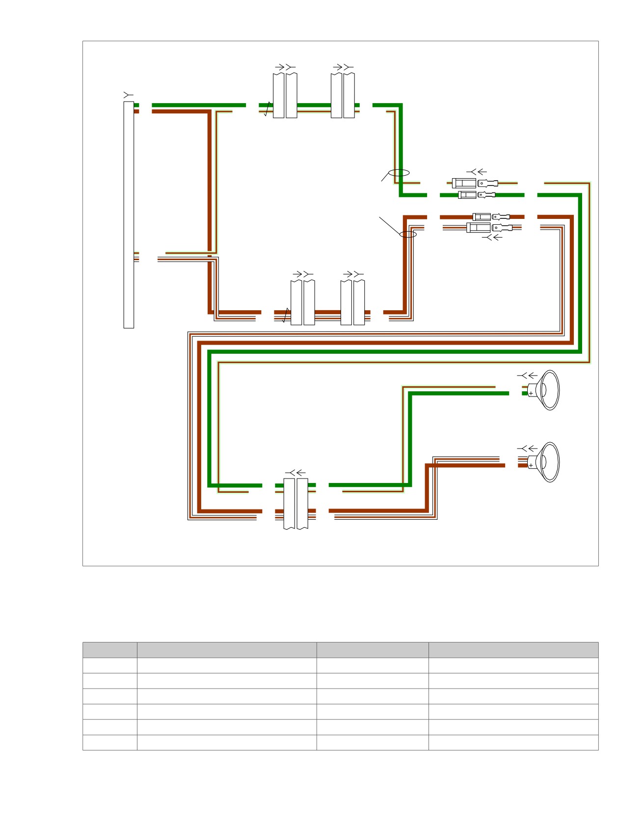
Figure 5-23. Sidecar Speaker Circuit
Table 5-25. Wire Harness Connectors
NO.
DESCRIPTION
TYPE
LOCATION
[28]
Radio
35-Place Amp
Inner fairing - back of radio (left side)
[36]
Rear right speaker
Spade Contacts
Inside rear right speaker box
[37]
Rear left speaker
Spade Contacts
Inside rear left speaker box
[41]
Rear right speaker/passenger controls
6-Place Mini-Deutsch
Inside rear right speaker box
[42]
Rear left speaker/passenger controls
6-Place Mini-Deutsch
Inside rear left speaker box
[197]
Sidecar console
12-Place Mini-Deutsch
Inside sidecar console
2008 Touring Diagnostics: Audio System 5-57
HOME
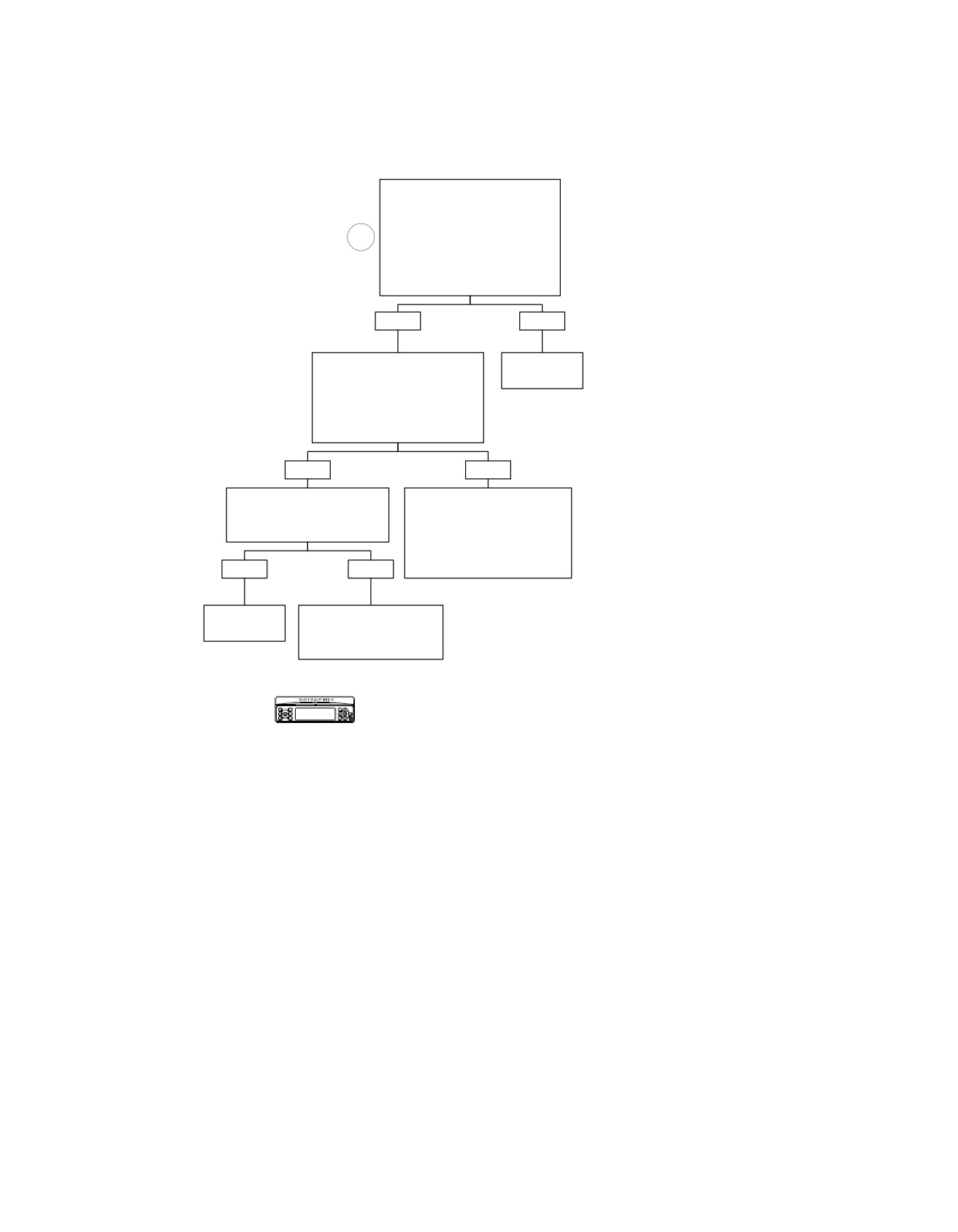
Sidecar Speakers Open: DTC B2025
Disconnect Connector [28].
Install Breakout Box HD-47918
Leaving Radio Disconnected.
Measure Resistance Between
1
Terminals “2” and “25” (Left
Speaker) or Between Terminals
“1” and “24” (Right Speaker) on
Connector [28].
Is Resistance Greater Than 3 Ohms?
YES
NO
Disconnect Sidecar Speaker at
Replace
Connector [37] (Left) or Connector
Radio.
[36] (Right). Measure Resistance
at Connectors [37E] (Left)
6101
or Connectors [36E] (Right).
Is Resistance Greater Than 3
Ohms?
YES
NO
Measure Resistance Across
Locate and Repair Open
Sidecar Speaker Terminals.
Between Terminals “2” or “25” and
Is Resistance Greater Than 3
Left Speaker, or Between Terminals
Ohms?
“1” or “24” and Right Speaker
on Harness From Connector
[28] on Harness From Radio to
YES
NO
Rear Speaker.
6119
Replace
Locate and Repair Open
Speaker.
Between Sidecar Speaker
and Connector [37E] (Left)
6943
or Connector [36E] (Right).
6972
Verify DTC is no longer present using radio
diagnostics. See RADIO DIAGNOSTICS.
Confirm proper operation with no DTCs.
fc00517_en
5-58 2008 Touring Diagnostics: Audio System
HOME
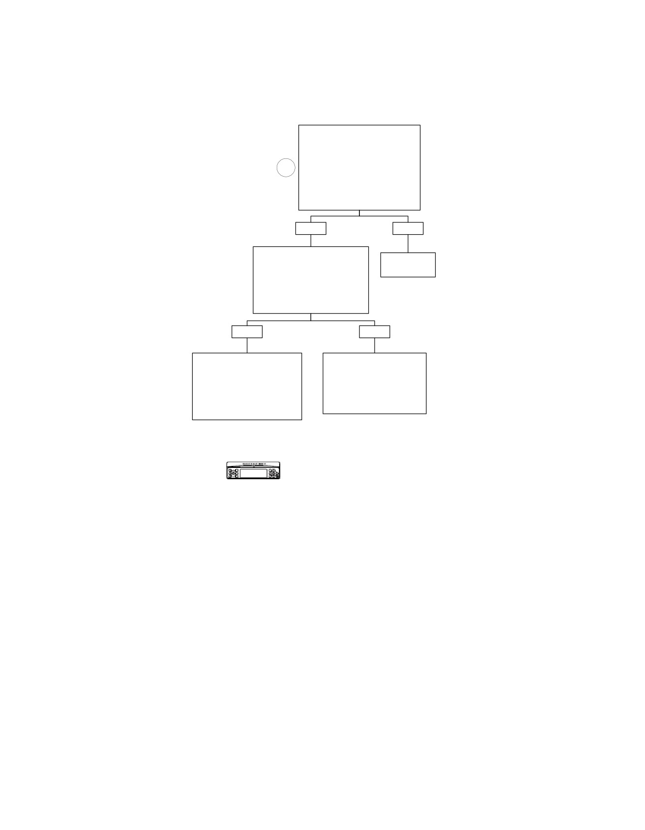
Sidecar Speakers Shorted to Ground: DTC B2026
Disconnect Connector [28].
Install Breakout Box HD-47918
Leaving Radio Disconnected.
Measure Continuity to Ground
Between Terminals “2” or “25” (Left
1
Speaker) and Ground, or
Between Terminals “1” or “24”
(Right Speaker) and Ground on
Breakout Box.
Is Continuity Present?
YES
NO
Disconnect Sidecar Speaker at
Connector [37] (Left) or Connector
Replace
[36] (Right). Measure Resistance
Radio.
Between Terminals “2” or “25”
(Left Speaker) and Ground, or
6101
Between Terminals “1” or “24”
(Right Speaker) and Ground.
Is Continuity Present?
YES
NO
Locate and Repair Short
Locate and Repair Short
Between Terminals “2” or “25” (Left
to Ground Between Sidecar
Speaker) and Ground, or
Speaker and Connector
Between Terminals “1” or “24”
[37E] (Left Speaker) or
(Right Speaker) and Ground on
Connector [36E] (Right
Harness From Connector [28] to
Speaker).
Connector [37] (Left Speaker) or
Connector [36] (Right Speaker).
6971
6118
Verify DTC is no longer present using radio
diagnostics. See RADIO DIAGNOSTICS.
Confirm proper operation with no DTCs.
fc00518_en
2008 Touring Diagnostics: Audio System 5-59
HOME
Sidecar Speakers Shorted to Battery: DTC B2027
Disconnect Connector [28].
Install Breakout Box HD-47918.
Turn Ignition ON. Measure Voltage
Between Terminals “2” or “25”
1
(Left Speaker) and Ground, or
Between Terminals “1” or “24”
(Right Speaker) and Ground on
Breakout Box.
Is Voltage Present?
YES
NO
Disconnect Sidecar Speaker at
Connector [37] (Left Speaker) or
Replace
Connector [36] (Right Speaker).
Radio.
Check for Voltage on Terminals “2”
(BN) or “25” (W/BN) for Left Sidecar
6101
Speaker, and Terminals “1”
(GN) or “24” (LGN/BN) for Right
Sidecar Speaker.
Is Voltage Present?
YES
NO
Locate and Repair Short to
Locate and Repair Short to Voltage
Voltage on Terminals “2” (BN)
on Terminals “2” (BN) or “25”
(W/BN) for Left Sidecar Speaker,
or “25” (W/BN) for Left Sidecar
or Terminals “1” (GN) or “24” (LGN/
Speaker, or Terminals “1”
BN) for Right Sidecar Speaker
(GN) or “24” (LGN/BN) for
on Harness Between Sidecar
Right Sidecar Speaker on
Speaker and Rear Speaker.
Harness Between Sidecar
Speaker and Rear Speaker.
6118
6971
Verify DTC is no longer present using radio
diagnostics. See RADIO DIAGNOSTICS.
fc00519_en
Confirm proper operation with no DTCs.
5-60 2008 Touring Diagnostics: Audio System
HOME
SERIAL DATA BUS DIAGNOSTICS
5.4
GENERAL
STARTS THEN STALLS: DTC U1300, U1301
There are two serial data BUSs. The first one is the J1850
The typical serial data voltage range is 0 volts (inactive) to 7
serial data BUS which communicates between the radio and
volts (active). Due to the short pulse, voltages will be much
the ECM, TSSM and instruments. The second serial data BUS
lower on a DVOM. In analog mode, a DVOM reading serial
is the Infotainment BUS, which uses a CAN protocol to com-
data will show continuous voltage when active, typically 0.6-
municate between the radio and the other radio accessories.
0.8 volts. The range for acceptable operations is greater than
The radio captures any errors found on both serial data BUSs
0 and less than 7.0 volts.
and stores them as DTCs.
NOTE
Problems in the fuel system or idle air control system may also
Table 5-26. J1850 Serial Data Bus
create this symptom.
DTC
DESCRIPTION
Diagnostic Tips
U1016
J1850 lost communications with ECM
•
If serial data is shorted, these codes will automatically trip
U1300
J1850 bus shorted low
the check engine light.
U1301
J1850 bus shorted high
•
DTCs P1009 and P1010 may accompany DTCs U1300
and U1301.
Table 5-27. Infotainment BUS
•
If radio ground and antenna ground are open, a serial data
BUS fault may occur causing a start and stall condition.
DTC
DESCRIPTION
U1302
Infotainment BUS off error
DIAGNOSTICS
U1306
Infotainment BUS lost communications with hands
PART NUMBER
TOOL NAME
free phone module
HD-41404-B
HARNESS CONNECTOR TEST KIT
U1307
Infotainment BUS lost communications with CB
HD-43876
BREAKOUT BOX
U1308
Infotainment BUS lost communications with future
U1312
Infotainment BUS lost communications with future
Diagnostic Notes
U1313
Infotainment BUS lost communications with XM
Each reference number below correlates to a circled number
on the flow chart(s).
U1314
Infotainment BUS lost communications with naviga-
tion
1. Install RADIO BREAKOUT BOX (Part No. HD-47918).
U1317
Infotainment BUS lost communications with high
2. Connect BREAKOUT BOX (Part No. HD-43876)between
output amplifier
wire harness and ECM. See 4.7 BREAKOUT BOX: EFI.
LOSS OF SERIAL DATA: DTC U1016
3. Use HARNESS CONNECTOR TEST KIT (Part No. HD-
41404-B), black socket probes and patch cord.
The serial data connector provides a means for the ECM,
TSM/TSSM and speedometer to communicate their current
4. This 18-place connector is located on the hands free
status. When all operating parameters on the serial data bus
phone module. Disconnect the connector and GENTLY
are within specifications, a state of health message is sent
touch the probes to the terminals to make the measure-
between the components. A diagnostic trouble code (DTC)
ment. Do not insert probe into connector.
U1016 indicates that the ECM is not capable of sending this
5. The amplifier fuse is an inline fuse for all accessory
state of health message.
installations and is mounted in the fuse block for FLHT-
CUSE models.
2008 Touring Diagnostics: Audio System 5-61
HOME
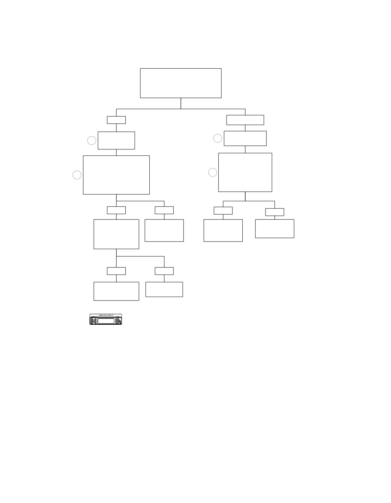
Loss of Serial Data: DTC U1016
Enter Radio Diagnostics Mode/AVC
Menu. Turn Ignition ON and Set
Run/Stop Switch to RUN. Rotate Wheel.
Are Speed Pulses on
Radio Display Greater Than 0?
YES
NO or Speed=0.
Install Breakout
Install Breakout
1
1
Box on Radio.
Box on Radio.
While Wiggling Harness,
Check Continuity
Check Continuity Between
Between Terminal “9” of
Radio Breakout Box (HD-
Radio Breakout Box
2
2
47918) Terminal “6” and
and Terminal “69” of ECM
ECM Breakout Box (HD-
Breakout Box.
43876) Terminal “69”.
Continuity Present?
Continuity Present?
YES
NO
YES
NO
Cycle Ignition Switch
Repair Open
to Check if DTC Still
Repair Intermittent
Replace ECM.
on (LGN/V)
Present. Test Ride if
on (LGN/V)
Reprogram and
Wire.
Necessary.
Wire.
Learn Password.
Does DTC U1016
6121
Return?
6130
6123
YES
NO
Replace ECM.
No Trouble
Reprogram and
Found.
Learn Password.
6125
Verify DTC is no longer present using radio
diagnostics. See RADIO DIAGNOSTICS.
fc00520_en
Confirm proper operation with no DTCs.
5-62 2008 Touring Diagnostics: Audio System
HOME
em00187
Radio
9
10
11
12
19
20
[27A]
[27B]
9
10
11
12
19
20
ABS
9
1
[166A]
9
1
[166B]
1
2
3
12
[30B]
1
2
3
12
[30A]
[39B]
1
2
5
7
[39A]
TSM/TSSM/HFSM
1
2
5
7
[108B]
1
2
5
7
[108A]
1
2
5
7
Speedometer
To
Tachometer
lighting
15A
relay
[1B] [1A]
Instruments
Fuse
1
1
1
O
BK/GN
2
Main To Interconnect
Data Link
GY
3
Harness
4
[2A]
GY
4
4
[2B]
To 15A
[91A]
Main To Interconnect
ignition
Harness
fuse
To 15A
O/BE
9
9
radio power
fuse
69
[78B]
15A
Battery
69
[78A]
Fuse
ECM
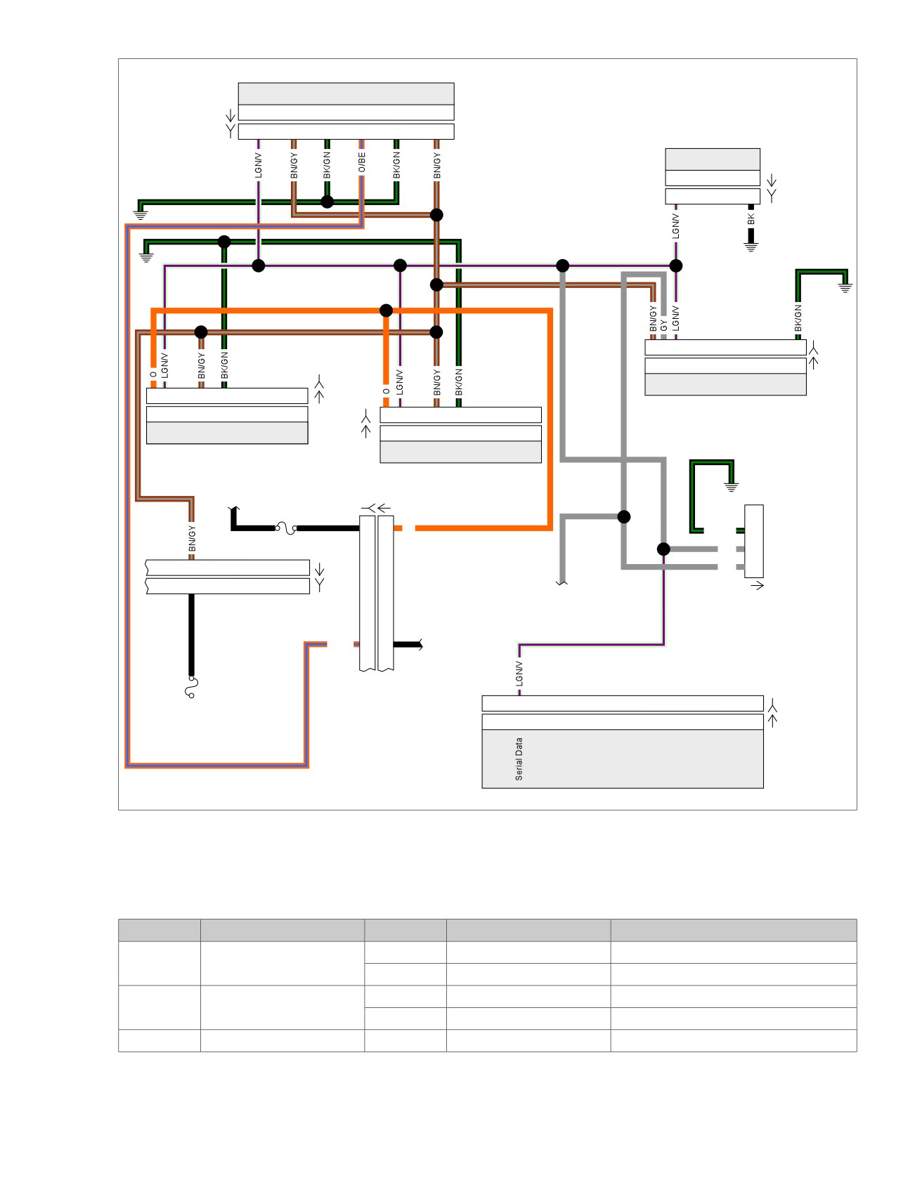
Figure 5-24. Serial Data Circuit: FLHX, FLHT/C/U, FLTR
Table 5-28. Wire Harness Connectors
NO.
DESCRIPTION
MODEL
TYPE
LOCATION
[1]
Main to interconnect har-
FLHT/C
16-Place Molex (Black)
Inner fairing - right radio support bracket
ness
FLTR
16-Place Molex (Black)
Inner fairing - below radio (right side)
[2]
Main to interconnect har-
FLHT/C
12-Place Molex (Gray)
Inner fairing - right fairing support brace
ness
FLTR
12-Place Molex (Gray)
Inner fairing - below radio (right side)
[27]
Radio
All
23-Place Amp
Inner fairing - back of radio (right side)
2008 Touring Diagnostics: Audio System 5-63

HOME
Table 5-28. Wire Harness Connectors
NO.
DESCRIPTION
MODEL
TYPE
LOCATION
[30]
TSM/TSSM/HFSM
All
12-Place Deutsch
Cavity in crossmember at rear of battery
box (under seat)
[39]
Speedometer
FLHT/C
12-Place Packard
Inner fairing (back of speedometer)
FL
TR
12-Place Packard
Under bezel (back of speedometer)
[78]
Electronic Control Module
All
73-Place Packard
Under right side cover
(ECM)
[91]
Data link connector
All
4-Place Deutsch
Under right side cover
[108]
T
achometer
FLHT/C
12-Place Packard
Inner fairing (back of tachometer)
FL
TR
12-Place Packard
Under bezel (back of tachometer)
[166]
ABS module
All
20-Place Molex
Under right side cover
5-64 2008 Touring Diagnostics: Audio System
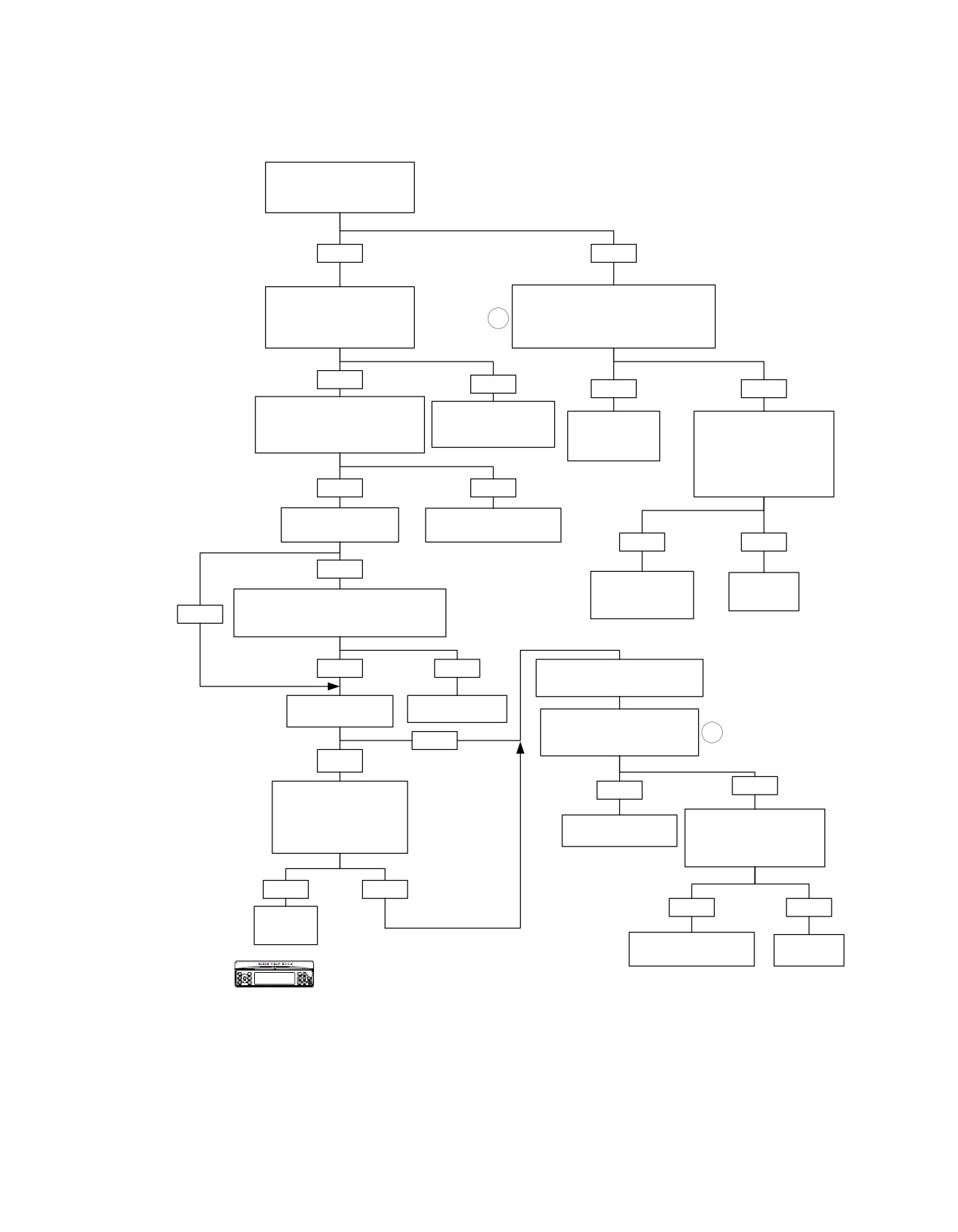
HOME
Starts, Then Stalls: DTC U1300, U1301
Set Engine Stop Switch to RUN.
Turn ignition key ON.
Is "BUS Er" present on
odometer?
YES
NO
Turn ignition key OFF.
Turn ignition key OFF. While wiggling
Disconnect ECM at connector
harness, check for continuity to ground at
[78]. Turn ignition key ON.
3
Terminal “3” of connector [91A].
Is "BUS Er" present on
Is continuity to ground present at any time?
odometer?
YES
NO
YES
NO
Turn ignition key OFF.
Replace ECM.
Disconnect TSM/TSSM/HFSM at
Reprogram and perform
Locate and repair
Turn ignition switch ON.
connector [30]. Turn ignition key ON.
password learn.
intermittent short
While wiggling harness,
Is "BUS Er" present on odometer?
to ground.
check for voltage at Terminal
“3” of connector [91A].
Is voltage present at
YES
NO
any time?
Is vehicle equipped
Replace TSM/TSSM.
with a tachometer?
Perform password learn.
YES
NO
YES
Locate and repair
No problem
intermittent short
found.
Turn ignition key OFF. Disconnect tachometer
to voltage.
NO
at connector [108]. Turn ignition key ON.
Is "BUS Er" present on odometer?
YES
NO
Turn ignition key OFF. Disconnect
speedometer at connector [39].
Is vehicle equipped
Replace tachometer.
with sound system?
Check for continuity to ground at
Terminal “3” of connector [91A].
3
NO
Is continuity to ground present?
YES
NO
Turn ignition switch OFF.
YES
Disconnect connector [27].
Turn ignition switch ON.
Turn ignition switch ON.
Locate and repair short
Is "BUS Er" present on
Check for voltage at Terminal
to ground.
odometer?
“3” of connector [91A].
Is voltage present?
YES
NO
YES
NO
Replace
radio.
Locate and repair short
Replace
to voltage.
speedometer.
Verify DTC is no longer present using radio
diagnostics. See RADIO DIAGNOSTICS. Confirm
fc00521_en
proper operation with no DTCs.
2008 Touring Diagnostics: Audio System 5-65
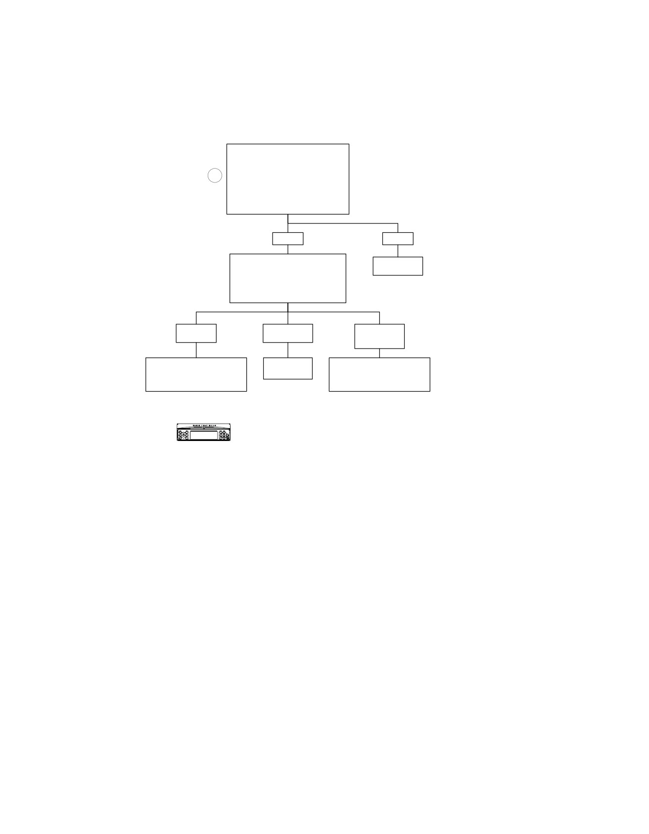
HOME
Infotainment Bus Off Error: DTC U1302 (Part 1 of 3)
Install Breakout Box HD-47918
to Radio Leaving Harness Connector
[28B] Disconnected. With
2
Ignition ON, Measure Voltage
Between Terminals “13” (-) and “14”
(+) on Breakout Box [28].
Is Voltage 4-6V?
YES
NO
Reconnect Breakout Box
Replace
HD-47918 to Harness. Measure
Radio.
Voltage Between Terminals “13” (-)
6102
and “14” (+) on Breakout Box [28].
What is Voltage?
0 Volts
4-6 Volts
Battery
Voltage
Go to INFOTAINMENT BUS
Replace
Go to INFOTAINMENT BUS
OFF ERROR:
Radio.
OFF ERROR:
DTC U1302 (Part 2 of 3).
DTC U1302 (Part 3 of 3).
6102
Verify DTC is no longer present using radio
diagnostics. See RADIO DIAGNOSTICS.
fc00522_en
Confirm proper operation with no DTCs.
5-66 2008 Touring Diagnostics: Audio System
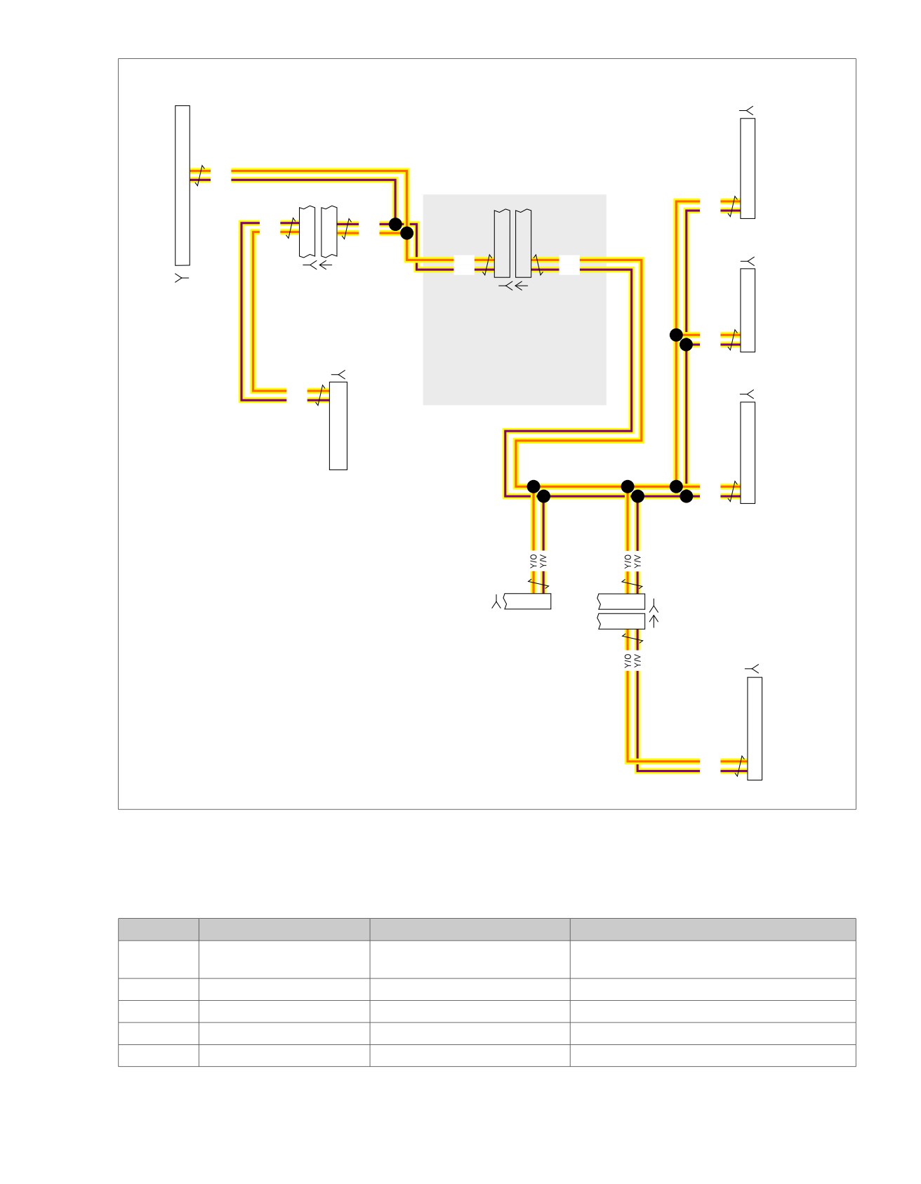
HOME
em00188
[185B]
XM Module
13
Y/O
To
14
Y/V
ultra
radio
Y/O
11
Y/V
12
[28A]
Y/V
5
5
Y/V
Y/O
4
4
Y/O
[186B]
Y/O
11
11
Y/O
Y/V
12
12
Y/V
[6B] [6A]
[28B]
C.B. [184B] [184C]
(BK)
Future
Interconnect
P/N 70169-06 - P&A non-ultra
Y/O
11
harness replaces P/N's
Y/V
12
70160-06 & 70164-06 and is
[149B]
represented when this
connector does not exist.
[184D]
Y/O
1
For all except FLHTCUI
Y/V
2
CB Module
High Output
Y/O
11
Amplifier
Y/V
12
P/N 70164-06
P&A ultra
overlay harness
for FLHTCU
only
FUTURE
[175B]
3 4
7
8
[187B]
7
8
[187A]
[194B]
Hands Free
Module
Y/O
17
Y/V
18
Figure 5-25. Infotainment BUS Circuit
Table 5-29. Wire Harness Connectors
NO.
DESCRIPTION
TYPE
LOCATION
[6]
Audio to interconnect har-
6-Place Deutsch (Black)
Inner fairing - left side of radio
ness
[28]
Radio
35-Place Amp
Inner fairing - back of radio (left side)
[149]
High output amplifier
23-Place Amp
Under luggage rack (right side)
[175]
Future
-
-
[184]
CB module
12-Place Mini-Deutsch
Inner fairing - left side of radio
2008 Touring Diagnostics: Audio System 5-67

HOME
Table 5-29. Wire Harness Connectors
NO.
DESCRIPTION
TYPE
LOCATION
[185]
XM module
12-Place Mini-Deutsch
Inner fairing - top of radio
[186]
Future
-
-
[187]
Hands-free phone module
12-Place Mini-Deutsch
Inner fairing - top of radio (left side)
[194]
Hands-free phone module
54-Place Amp
Inside Tour-Pak (left side)
5-68 2008 Touring Diagnostics: Audio System
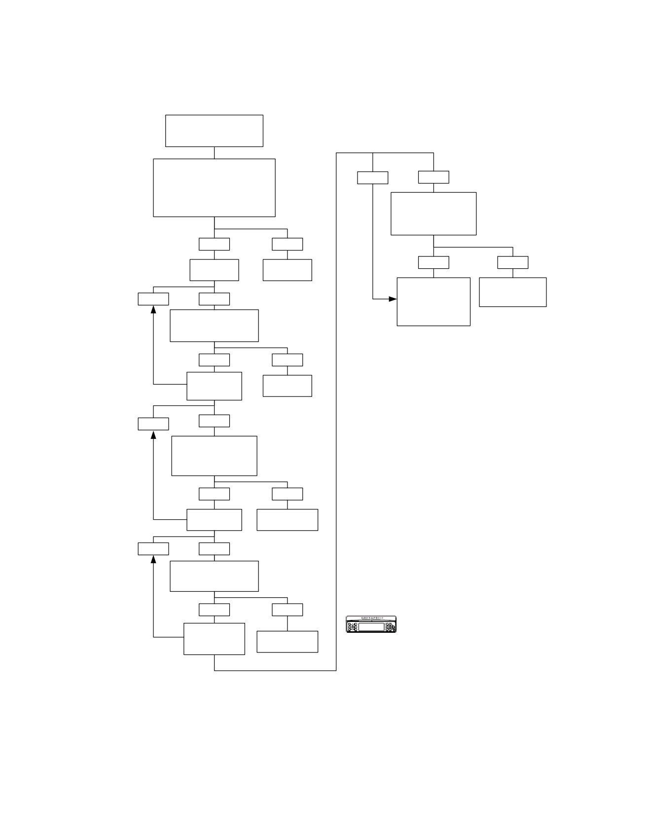
HOME
Infotainment Bus Off Error: DTC U1302 (Part 2 of 3)
From INFOTAINMENT BUS
OFF ERROR:
DTC1302 (Part 1 of 3).
Disconnect Breakout Box From
Radio Leaving Harness Connected.
NO
YES
Measure Continuity
Between Terminals “13” and “14” to
Ground on HD-47918 [28].
Disconnect Hands Free
Is Continuity Present?
Phone Module Connector
[194B].
Is Continuity Still Present?
YES
NO
YES
NO
CB
Replace
Installed?
Radio.
Locate and Repair
Replace Hands
6102
Short to Ground
Free Phone
NO
YES
on (Y/O) or (Y/V)
Module.
Wires in Appropriate
Disconnect CB Connector
Harness.
[184B].
Is Continuity Still Present?
YES
NO
High Output
Replace
Amplifier
CB Module.
Installed?
6625
YES
NO
Disconnect High Output
Amplifier Connector
[149B].
Is Continuity Still Present?
YES
NO
XM
Replace High
Installed?
Output Amplifier.
6108
NO
YES
Disconnect XM Connector
[185B].
Is Continuity Still Present?
YES
NO
Verify DTC is no longer present using radio
diagnostics. See RADIO DIAGNOSTICS.
Hands Free
Confirm proper operation with no DTCs.
Phone Module
Replace XM
Installed?
Module.
6126
fc00523_en
2008 Touring Diagnostics: Audio System 5-69
HOME
Infotainment Bus Off Error: DTC U1302 (Part 3 of 3)
From INFOTAINMENT BUS
OFF ERROR:
DTC U1302 (Part 1 of 3).
Disconnect Breakout Box From
Radio Leaving Harness
Connected. With Ignition ON,
NO
YES
Measure Voltage Between Terminals
“13” and “14” to Ground on
Disconnect Hands Free
HD-47918 [28].
Phone Module Connector
Is Battery Voltage Present?
[194B].
Is Battery Voltage Still
Present?
YES
NO
CB
Replace
YES
NO
Installed?
Radio.
6101
Locate and Repair
Replace Hands
YES
Short to Voltage on
Free Phone
NO
Module.
(Y/O) or (Y/V) Wires
Disconnect CB Connector
in Appropriate
[184B].
Harness.
Is Battery Voltage Still
Present?
YES
NO
High Output
Replace
Amplifier
CB Module.
Installed?
6625
NO
YES
Disconnect High Output
Amplifier Connector
[149B].
Is Battery Voltage Still
Present?
YES
NO
XM
Replace High
Installed?
Output Amplifier.
6108
NO
YES
Disconnect XM Connector
[185B].
Is Battery Voltage Still
Present?
YES
NO
Replace XM
Hands Free
Verify DTC is no longer present using radio
Module.
Phone Module
diagnostics. See RADIO DIAGNOSTICS.
Installed?
6126
Confirm proper operation with no DTCs.
fc00524_en
5-70 2008 Touring Diagnostics: Audio System