Harley Davidson 2008 Touring Models. Electrical Diagnostics Manual - page 22
HOME
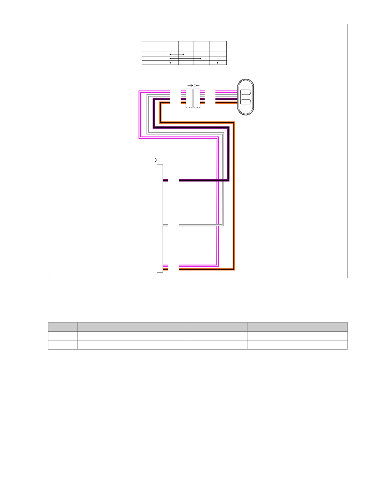
em00181
Left & Right Rear
Passenger Controls
COLOR
ORANGE/
PINK/
VIOLET/
GRAY/
POSITION
BLACK
WHITE
BLACK
WHITE
UP/+VOL
MODE/PTT
DOWN/-VOL
Right Rear
Speaker &
Controls
[41A] [41B]
(BK)
PK/W
1
1
PK/W
+VOL
GY/W
2
2
GY/W
PTT
V/BK
3
3
V/BK
O/BK
4
4
O/BK
-VOL
(BK)
[28B]
11
V/BK
To
ultra
radio
[28A]
23
GY/W
34
PK/W
35
O/BK
Figure 5-14. Passenger Audio/PTT Switch Circuit
Table 5-15. Wire Harness Connectors
NO.
DESCRIPTION
TYPE
LOCATION
[28]
Radio
35-Place Amp
Inner fairing - back of radio (left side)
[41]
Rear right speaker/passenger controls
6-Place Mini-Deutsch
Inside rear right speaker box
2008 Touring Diagnostics: Audio System 5-31
HOME
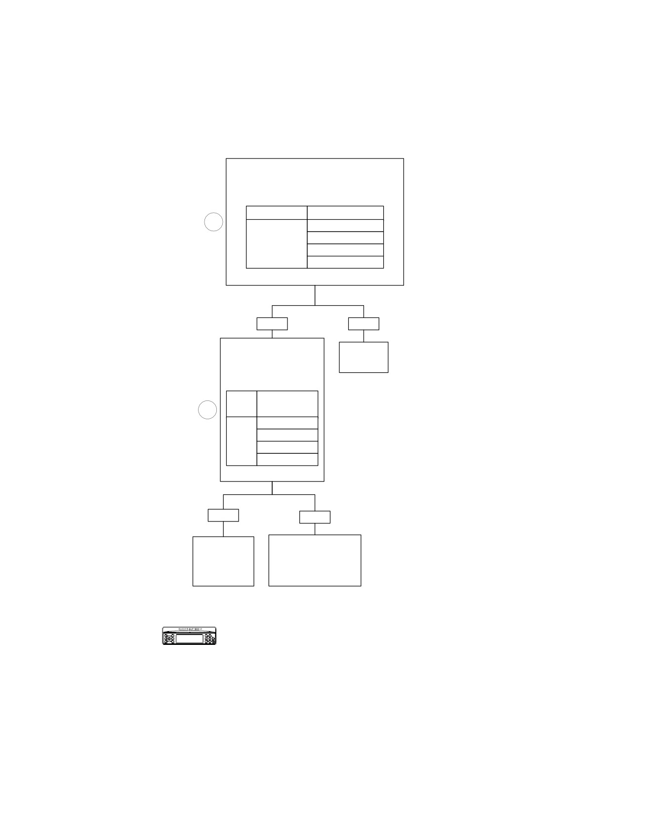
Passenger Mode Switch Shorted Low: DTC B2011 (Part 2 of 2)
Remove Outer Fairing. Connect Breakout Box
Leaving Connector [28B] Disconnected from
Radio. With Key OFF, Check for Continuity to
Ground at Connector [28B].
From (-)
To Terminal (+)
1
“34” (PK/W)
“23” (GY/W)
Ground
“11” (V/BK)
“12” (BN/W)
Any Continuity Present?
YES
NO
Disconnect Connector [42].
With Key OFF, Check
Replace
for Continuity to Ground at
Radio.
Connector [42A] at Wire
Indicated
6101
on Radio Display.
To
From
Terminal
3
(-)
(+)
“1” (PK/W)
“2” (GY/W)
Ground
“3” (V/BK)
“4” (BN/W)
Any Continuity Present?
YES
NO
Locate and Repair Short in
Locate and
Passenger Rear Control
Repair Short in
Switch Harness at Wire
Audio Harness at
Indicated on Radio Display
Wire Indicated
[(BN/W) Wire Becomes
on Radio Display.
(O/BK) in Speaker Box].
6560
6115
Verify DTC is no longer present using radio
diagnostics. See RADIO DIAGNOSTICS.
fc00502_en
Confirm proper operation with no DTCs.
5-32 2008 Touring Diagnostics: Audio System
HOME
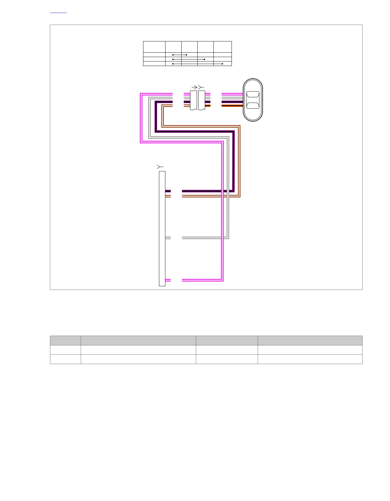
em00182
Left & Right Rear
Passenger Controls
COLOR
ORANGE/
PINK/
VIOLET/
GRAY/
POSITION
BLACK
WHITE
BLACK
WHITE
UP/+VOL
MODE/PTT
Left Rear
DOWN/-VOL
Speaker &
Controls
[42A] [42B]
(BK)
PK/W
1
1
PK/W
UP
GY/W
2
2
GY/W
MODE
V/BK
3
3
V/BK
BN/W
4
4
O/BK
DOWN
(BK)
[28B]
11
V/BK
12
BN/W
To
ultra
radio
[28A]
23
GY/W
34
PK/W
Figure 5-15. Passenger Mode Switch Circuit
Table 5-16. Wire Harness Connectors
NO.
DESCRIPTION
TYPE
LOCATION
[28]
Radio
35-Place Amp
Inner fairing - back of radio (left side)
[41]
Rear left speaker/passenger controls
6-Place Mini-Deutsch
Inside rear left speaker box
2008 Touring Diagnostics: Audio System 5-33
HOME
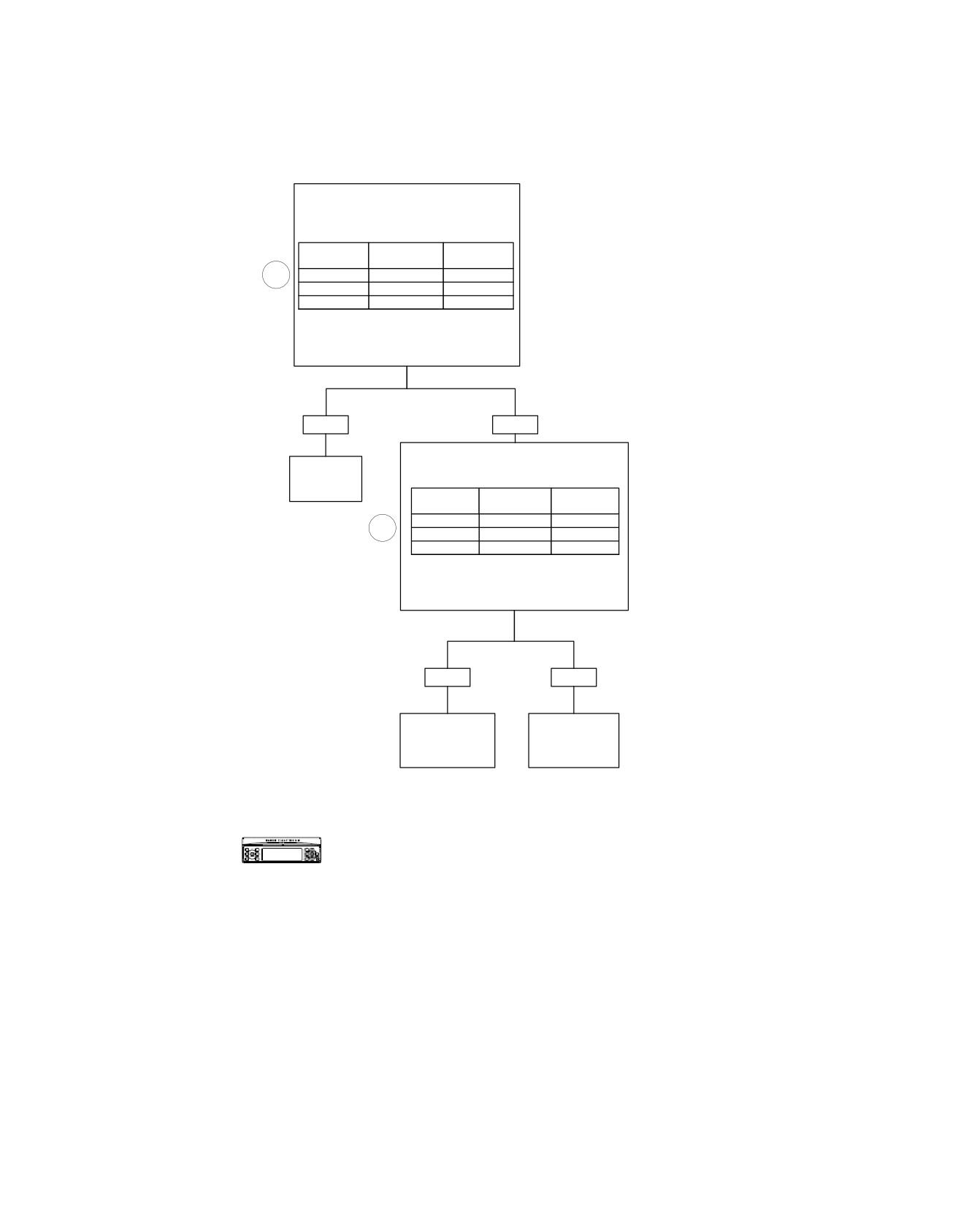
Passenger Audio/PTT Switch Stuck or Open: DTC B2012 (Part 1 of 2)
Remove Outer Fairing. Connect Breakout
Box Leaving Connector [28B] Disconnected
from Radio. With Switch Depressed, Check
for Continuity at Connector [28B].
Switch
From
To
Position
Terminal
Terminal
1
Vol. Up
“35” (O/BK)
“34” (PK/W)
Vol. Dn
“35” (O/BK)
“23” (GY/W)
PTT
“35” (O/BK)
“11” (V/BK)
Each Wire Pair Should be Less than 0.5
Ohms While Switch is Depressed and Infinity
While Switch is Open.
Is It?
YES
NO
Disconnect Connector [41]. With
Switch Depressed, Check for
Replace
Continuity at Connector [41B].
Radio.
Switch
From
To
Position
Terminal
Terminal
6101
Vol. Up
“4” (O/BK)
“1” (PK/W)
3
Vol. Dn
“4” (O/BK)
“2” (GY/W)
PTT
“4” (O/BK)
“3” (V/BK)
Each Wire Pair Should be Less than
0.5 Ohms While Switch is Depressed
and Infinity While Switch is Open.
Is It?
YES
NO
Locate and
Replace Rear
Repair Open or
Volume/PTT
Replace Audio
Switch or Repair
Harness.
Switch Wiring.
6561
6627
Verify DTC is no longer present using radio
diagnostics. See RADIO DIAGNOSTICS.
Confirm proper operation with no DTCs.
fc00503_en
5-34 2008 Touring Diagnostics: Audio System
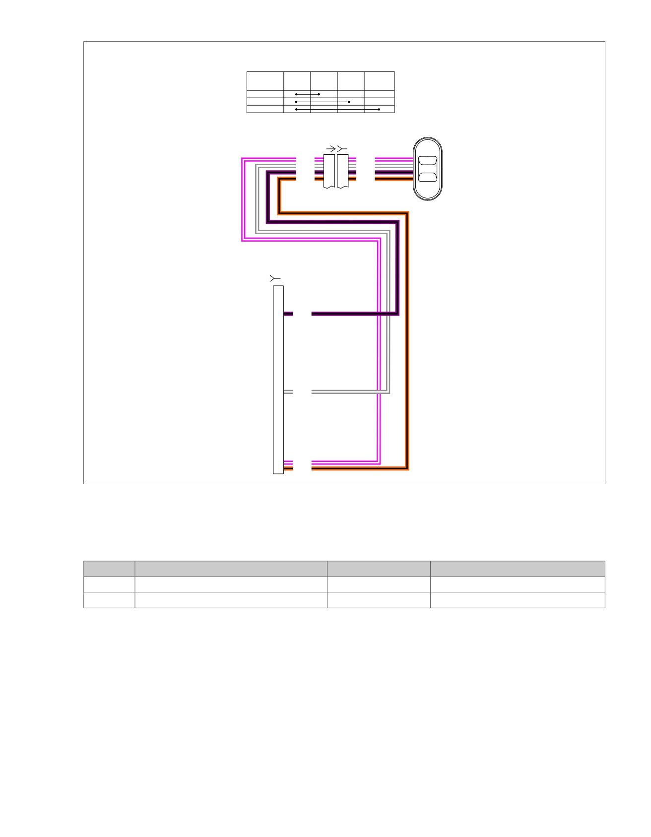
HOME
em00181
Left & Right Rear
Passenger Controls
COLOR
ORANGE/
PINK/
VIOLET/
GRAY/
POSITION
BLACK
WHITE
BLACK
WHITE
UP/+VOL
MODE/PTT
DOWN/-VOL
Right Rear
Speaker &
Controls
[41A] [41B]
(BK)
PK/W
1
1
PK/W
+VOL
GY/W
2
2
GY/W
PTT
V/BK
3
3
V/BK
O/BK
4
4
O/BK
-VOL
(BK)
[28B]
11
V/BK
To
ultra
radio
[28A]
23
GY/W
34
PK/W
35
O/BK
Figure 5-16. Passenger Audio/PTT Switch Circuit
Table 5-17. Wire Harness Connectors
NO.
DESCRIPTION
TYPE
LOCATION
[28]
Radio
35-Place Amp
Inner fairing - back of radio (left side)
[41]
Rear right speaker/passenger controls
6-Place Mini-Deutsch
Inside rear right speaker box
2008 Touring Diagnostics: Audio System 5-35
HOME
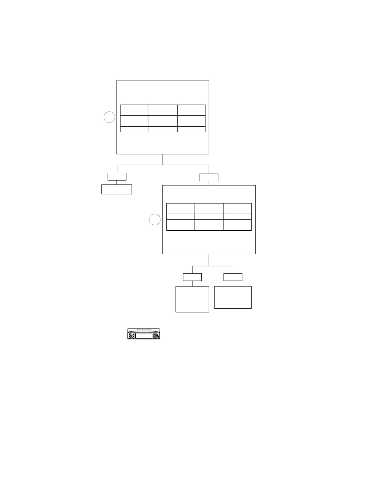
Passenger Mode Switch Stuck or Open: DTC B2012 (Part 2 of 2)
Remove Outer Fairing. Connect Breakout
Box Leaving Connector [28B] Disconnected
from Radio. With Switch Depressed, Check
for Continuity at Connector [28B].
Switch
From
To
Position
Terminal
Terminal
1
Mode Up
“12” (BN/W)
“34” (PK/W)
Mode Dn
“12” (BN/W)
“23” (GY/W)
Mode In
“12” (BN/W)
“11” (V/BK)
Each Wire Pair Should be Less than 0.5
Ohms While Switch is Depressed and Infinity
While Switch is Open.
Is It?
YES
NO
Replace Radio
Disconnect Connector [42]. With
Switch Depressed, Check for
6101
Continuity at Connector [42B].
Switch
From
To
Position
Terminal
Terminal
Mode Up
“4” (O/BK)
“1” (PK/W)
3
Mode Dn
“4” (O/BK)
“2” (GY/W)
Mode In
“4” (O/BK)
“3” (V/BK)
Each Wire Pair Should be Less than
0.5 Ohms While Switch is Depressed
and Infinity While Switch is Open.
Is It?
YES
NO
Locate and
Replace
Repair open
Mode Switch
or Replace
or Repair
Audio
Switch Wiring.
Harness.
6627
6561
Verify DTC is no longer present using radio
diagnostics. See RADIO DIAGNOSTICS. Confirm
proper operation with no DTCs.
fc00504_en
5-36 2008 Touring Diagnostics: Audio System
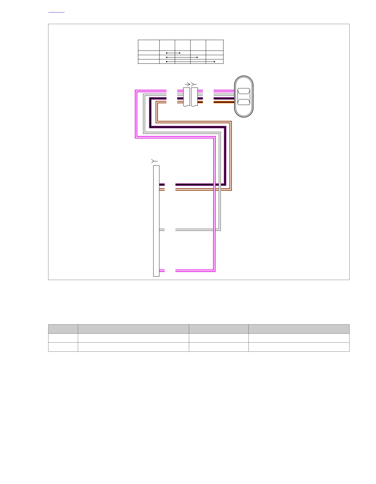
HOME
em00182
Left & Right Rear
Passenger Controls
COLOR
ORANGE/
PINK/
VIOLET/
GRAY/
POSITION
BLACK
WHITE
BLACK
WHITE
UP/+VOL
MODE/PTT
Left Rear
DOWN/-VOL
Speaker &
Controls
[42A] [42B]
(BK)
PK/W
1
1
PK/W
UP
GY/W
2
2
GY/W
MODE
V/BK
3
3
V/BK
BN/W
4
4
O/BK
DOWN
(BK)
[28B]
11
V/BK
12
BN/W
To
ultra
radio
[28A]
23
GY/W
34
PK/W
Figure 5-17. Passenger Mode Switch Circuit
Table 5-18. Wire Harness Connectors
NO.
DESCRIPTION
TYPE
LOCATION
[28]
Radio
35-Place Amp
Inner fairing - back of radio (left side)
[41]
Rear left speaker/passenger controls
6-Place Mini-Deutsch
Inside rear left speaker box
2008 Touring Diagnostics: Audio System 5-37
HOME
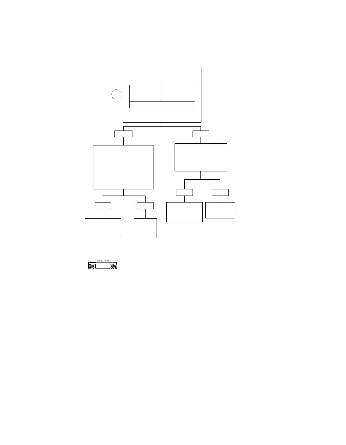
Sidecar Switches Shorted High: DTC B2013
With Key ON and Radio ON,
Check for Voltage at Breakout
Box.
From
To
1
Terminal
Terminal
(-)
(+)
“11”
“15”
Is Voltage Greater Than
2.7 Volts?
YES
NO
Inspect Connectors
Disconnect Connector [27B]
[27], [53] and [197]
from Radio While Leaving Breakout
for Corrosion.
Box Connected to Harness.
Is Corrosion Present?
With Ignition ON, Check for
Voltage at Terminals “11” (-) and
“15” (+) on Breakout Box.
Is Voltage Present?
YES
NO
YES
NO
Clean or
Replace
Repair
Radio.
Connector.
6101
Locate and
6112
Replace
Repair Short
Radio.
To Voltage.
6113
6101
Verify DTC is no longer present using radio
diagnostics. See RADIO DIAGNOSTICS.
fc00505_en
Confirm proper operation with no DTCs.
5-38 2008 Touring Diagnostics: Audio System
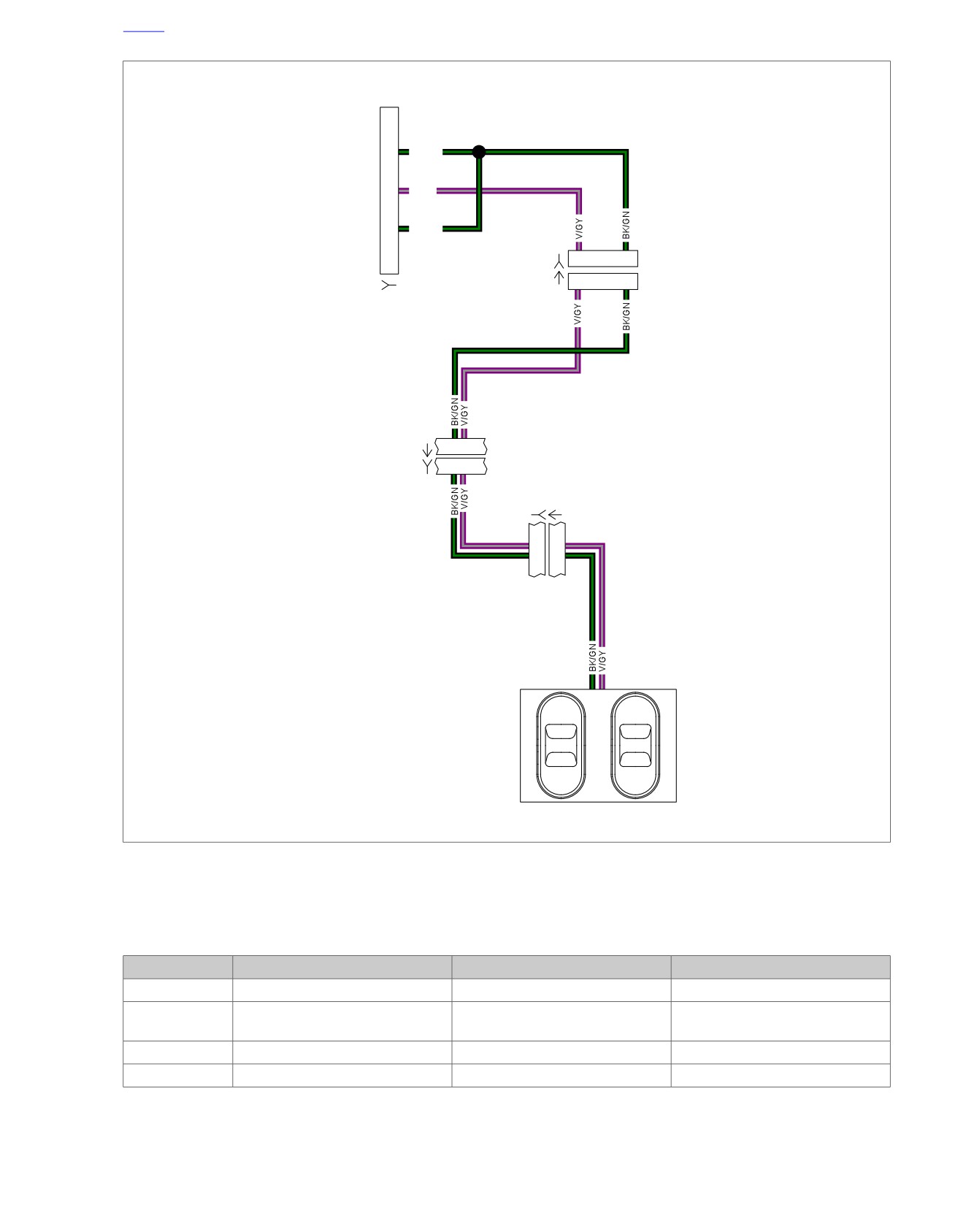
HOME
em00183
11
BK/GN
To
radio
[27A]
(BK)
15
V/GY
19
BK/GN
1
6
[6B]
[6A]
1
6
[27B]
Sidecar
Harness
88403-06
4 5
[53A]
(BK)
[53D]
4 5
[197B] [197A]
3
3
4
4
Sidecar
Console
Sidecar
UP
+VOL
Switches
MODE
PTT
DOWN
-VOL
Figure 5-18. Sidecar Switch Circuit
Table 5-19. Wire Harness Connectors
NO.
DESCRIPTION
TYPE
LOCATION
[6]
Audio to interconnect
6-Place Deutsch (Black)
Inner fairing - left side of radio
[27]
Radio
23-Place Amp
Inner fairing - back of radio (right
side)
[53]
Console pod
12-Place Mini-Deutsch (Black)
Rear of battery box (under seat)
[197]
Sidecar console
12-Place Mini-Deutsch (Black)
Inside sidecar console
2008 Touring Diagnostics: Audio System 5-39
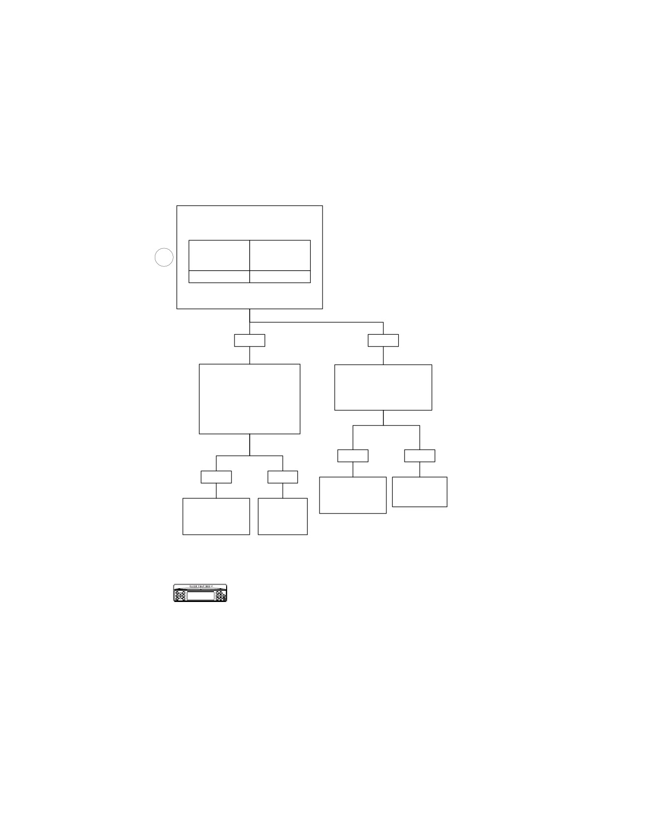
HOME
Sidecar Switches Shorted Low: DTC B2014
With Key ON and Radio ON,
Check for Voltage at Breakout
Box.
From
To
1
Terminal
Terminal
(-)
(+)
“11”
“15”
Is Voltage Less Than
0.25 Volts?
YES
NO
Disconnect Connector [27B]
Inspect Connectors
from Radio While Leaving
[27], [53] and [197]
Breakout Box Connected to
for Corrosion.
Harness. Check for Continuity
Is Corrosion Present?
at Terminals “11” and “15” on
Breakout Box.
Is Continuity Present?
YES
NO
YES
NO
Clean or
Replace
Repair
Radio.
Connector.
Locate and
Replace
6101
Repair Short
Radio.
6112
To Ground.
6113
6101
Verify DTC is no longer present using radio
diagnostics. See RADIO DIAGNOSTICS.
Confirm proper operation with no DTCs.
fc00506_en
5-40 2008 Touring Diagnostics: Audio System
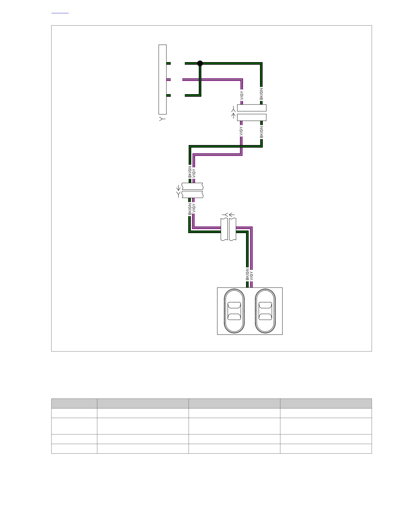
HOME
em00183
11
BK/GN
To
radio
[27A]
(BK)
15
V/GY
19
BK/GN
1
6
[6B]
[6A]
1
6
[27B]
Sidecar
Harness
88403-06
4 5
[53A]
(BK)
[53D]
4 5
[197B] [197A]
3
3
4
4
Sidecar
Console
Sidecar
UP
+VOL
Switches
MODE
PTT
DOWN
-VOL
Figure 5-19. Sidecar Switch Circuit
Table 5-20. Wire Harness Connectors
NO.
DESCRIPTION
TYPE
LOCATION
[6]
Audio to interconnect
6-Place Deutsch (Black)
Inner fairing - left side of radio
[27]
Radio
23-Place Amp
Inner fairing - back of radio (right
side)
[53]
Console pod
12-Place Mini-Deutsch (Black)
Rear of battery box (under seat)
[197]
Sidecar console
12-Place Mini-Deutsch (Black)
Inside sidecar console
2008 Touring Diagnostics: Audio System 5-41
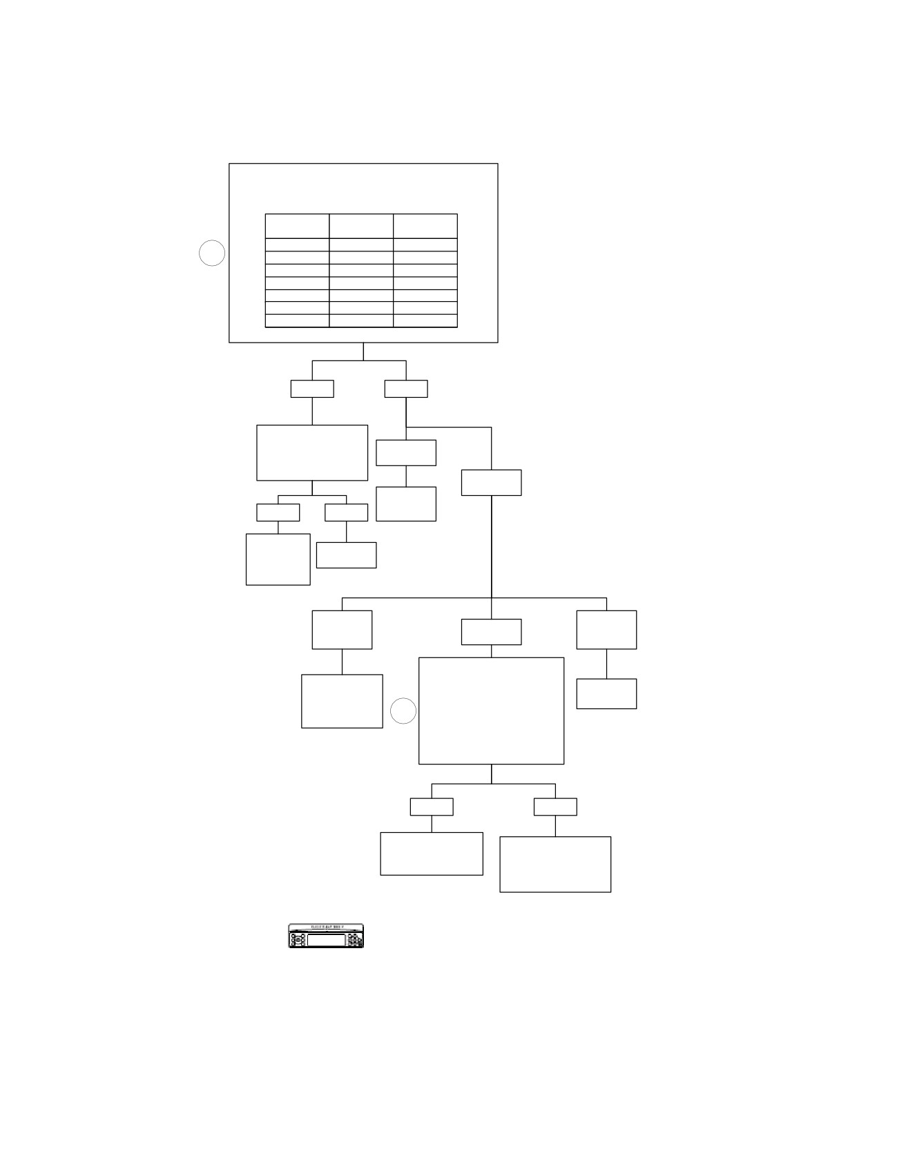
HOME
Sidecar Switches Stuck or Open: DTC B2015
With Key ON, Check for Voltage Between Terminals
“11” (-) and “15” (+) at Breakout Box.
Is Voltage Within Range for Each Function?
Sidecar
Minimum
Minimum
Button
Voltage
Voltage
No Press
2.13
2.48
1
Mode
1.88
2.21
PTT
1.66
1.94
Tune (+)
1.33
1.67
Volume (+)
0.90
1.33
Tune (-)
0.55
0.89
Volume (-)
0.33
0.54
YES
NO
Inspect Connectors
[27], [53] and [197]
0V
for Corrosion.
Is Corrosion Present?
Other
Replace
YES
NO
Radio.
6101
Clean or
Replace
Repair
Radio.
Connector.
6101
6112
Battery
0.45-4.7V
5V
Voltage
Disconnect Connector [197].
Measure Continuity Between
Replace
Terminal “15” on Breakout Box
Replace
Sidecar Console
and Terminal “3” on Connector
Radio.
Switch
4
[197A] and Also Between
Assembly.
6101
Terminal “19” on Breakout Box
6952
And Terminal “4” on
Connector [197A].
Is Continuity Present?
YES
NO
Replace Sidecar
Locate and
Console Switch
Repair Open on
Assembly.
(V/GY) or (BK/GN)
6952
Wire in Harness.
6113
Verify DTC is no longer present using radio
diagnostics. See RADIO DIAGNOSTICS. Confirm
proper operation with no DTCs.
fc00507_en
5-42 2008 Touring Diagnostics: Audio System
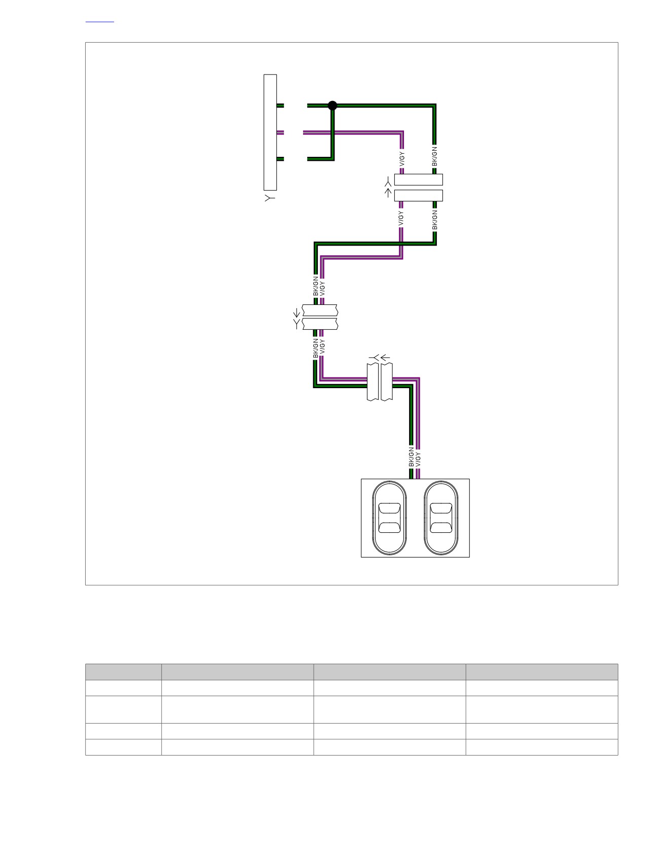
HOME
em00183
11
BK/GN
To
radio
[27A]
(BK)
15
V/GY
19
BK/GN
1
6
[6B]
[6A]
1
6
[27B]
Sidecar
Harness
88403-06
4 5
[53A]
(BK)
[53D]
4 5
[197B] [197A]
3
3
4
4
Sidecar
Console
Sidecar
UP
+VOL
Switches
MODE
PTT
DOWN
-VOL
Figure 5-20. Sidecar Switch Circuit
Table 5-21. Wire Harness Connectors
NO.
DESCRIPTION
TYPE
LOCATION
[6]
Audio to interconnect
6-Place Deutsch (Black)
Inner fairing - left side of radio
[27]
Radio
23-Place Amp
Inner fairing - back of radio (right
side)
[53]
Console pod
12-Place Mini-Deutsch (Black)
Rear of battery box (under seat)
[197]
Sidecar console
12-Place Mini-Deutsch (Black)
Inside sidecar console
2008 Touring Diagnostics: Audio System 5-43

HOME
RADIO SPEAKER DIAGNOSTICS: DTC
B2016-B2027
5.3
GENERAL
DIAGNOSTICS
The sound system is designed to capture faults for each of the
PART NUMBER
TOOL NAME
radio speaker outputs. When a fault is detected, a DTC is
HD-47918
RADIO BREAKOUT BOX
generated. The DTC and related data appears on the radio
display when the system is in the diagnostic mode.
Diagnostic Notes
Each reference number below correlates to a circled number
Table 5-22. Code Description
on the flow chart(s).
DTC
DESCRIPTION
1. Install RADIO BREAKOUT BOX (Part No. HD-47918).
B2016
Front speakers shorted
B2017
Front speakers open
B2018
Front speakers shorted to ground
B2019
Front speakers shorted to battery
B2020
Rear speakers shorted
B2021
Rear speakers open
B2022
Rear speakers shorted to ground
B2023
Rear speakers shorted to battery
B2024
Sidecar speakers shorted
B2025
Sidecar speakers open
B2026
Sidecar speakers shorted to ground
B2027
Sidecar speakers shorted to battery
5-44 2008 Touring Diagnostics: Audio System
HOME
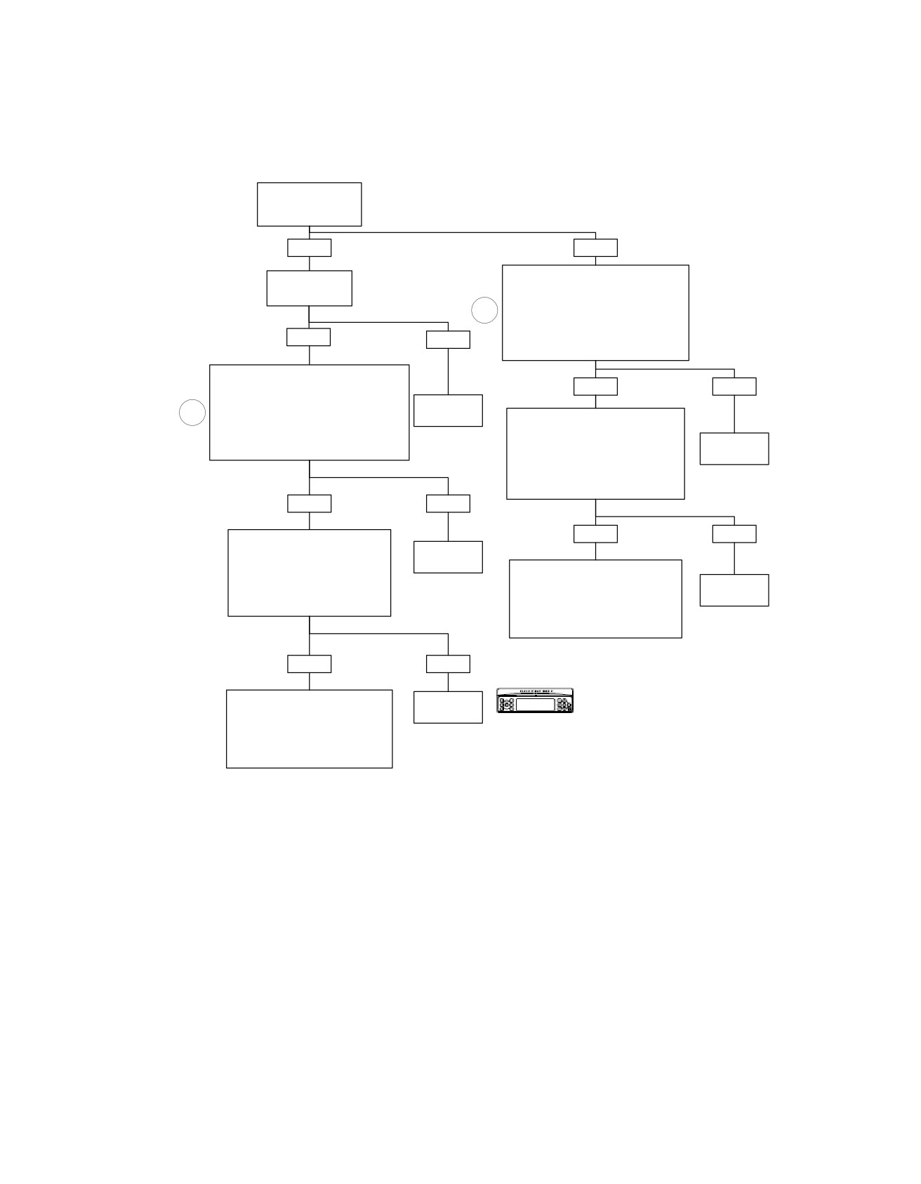
Front Speakers Shorted: DTC B2016
Is Optional Harley-
Davidson Amplifier
Installed?
YES
NO
Disconnect Connector [27]. Install
Inspect amplifier
Breakout Box HD-47918 Leaving
fuse.
Radio Disconnected. Measure
Is fuse good?
Resistance Between Terminals
1
“16” and “17” (Left Speaker) or
Between Terminals “1” and “18”
YES
NO
(Right Speaker) on Breakout Box.
Is Resistance Less Than One Ohm?
Disconnect Connector [149]. Install
Breakout Box HD-47918 to Amplifier
YES
NO
Harness Leaving Amplifier Disconnected.
Measure Resistance Between
Replace
1
Terminals “7” and “14” (Left Speaker) or
amplifier fuse.
Disconnect Speaker. Measure
Between Terminals “6” and “13” (Right
6130
Resistance Between Terminals
Speaker) on Breakout Box.
Replace
“16” and “17” (Left Speaker) or
Is Resistance Less Than One Ohm?
Radio.
Between Terminals “1” and “18”
(Right Speaker) on Breakout Box.
6101
Is Resistance Less Than One Ohm?
YES
NO
YES
NO
Disconnect Speaker. Measure
Replace
Resistance Between Terminals “7”
Amplifier.
and “14” (Left Speaker) or
Locate and Repair Short
Between Terminals “6” and “13”
6107
Between Terminals “16” and “17”
Replace
(Right Speaker) on Breakout Box.
(Left Speaker) or Between Terminals
Speaker.
Is Resistance Less Than One Ohm?
“1” and “18” (Right Speaker)
on Harness From Radio to
6605
Speaker.
6531
YES
NO
Verify DTC is no longer present using radio
Locate and Repair Short
Replace
diagnostics. See RADIO DIAGNOSTICS.
Between Terminals “7” and “14”
Speaker.
Confirm proper operation with no DTCs.
(Left Speaker) or Between Terminals
“6” and “13” (Right Speaker)
6605
on Harness From Amplifier to
Speaker.
6116
fc00508_en
2008 Touring Diagnostics: Audio System 5-45
HOME
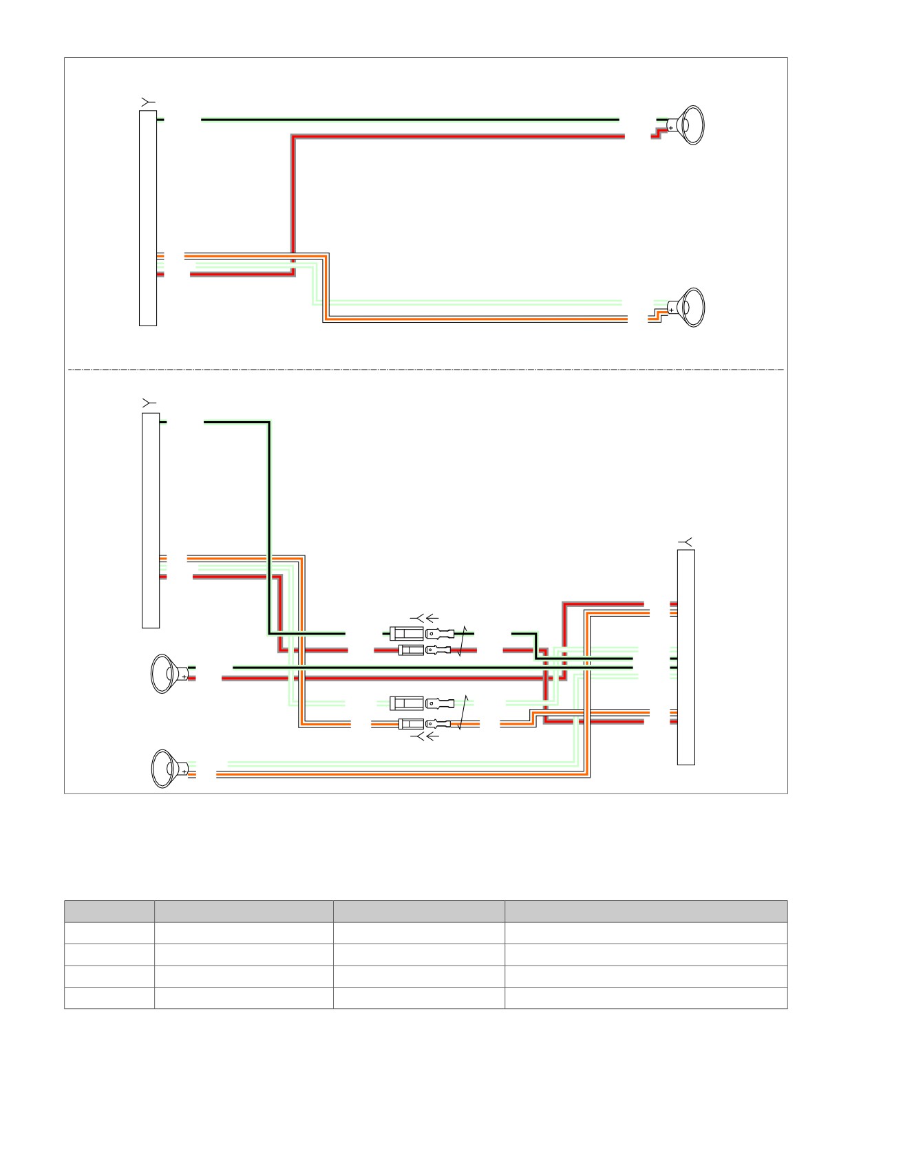
Front Speakers Without Amplifier
em00184
[27B]
Right
1
LGN/BK
LGN/BK
Front
GY/R
Speaker
[34B]
To
radio
[27A]
(BK)
16
W/O
17
LGN/W
18
GY/R
Left
LGN/W
Front
Speaker
W/O
[35B]
[27B]
1
LGN/BK
Front Speakers With Amplifier
To
radio
[27A]
(BK)
[149B]
16
W/O
17
LGN/W
18
GY/R
[34B] [34A]
GY/R
6
W/O
7
To
LGN/BK
LGN/BK
amplifier
[34B]
GY/R
GY/R
LGN/W
11
[149A]
Right
LGN/BK
12
(BK)
Front
LGN/BK
LGN/BK
13
GY/R
LGN/W
14
Speaker
LGN/W
LGN/W
W/O
18
W/O
W/O
GY/R
19
Left
[35B]
[35B] [35C]
Front
LGN/W
Speaker
W/O
Figure 5-21. Front Speaker Circuit
Table 5-23. Wire Harness Connectors
NO.
DESCRIPTION
TYPE
LOCATION
[27]
Radio
23-Place Amp
Inner fairing - back of radio (right side)
[34]
Front right speaker
Spade Contacts
Inner fairing - back of right speaker
[35]
Front left speaker
Spade Contacts
Inner fairing - back of left speaker
[149]
High output amplifier
23-Place Amp
Under luggage rack (right side)
5-46 2008 Touring Diagnostics: Audio System
HOME
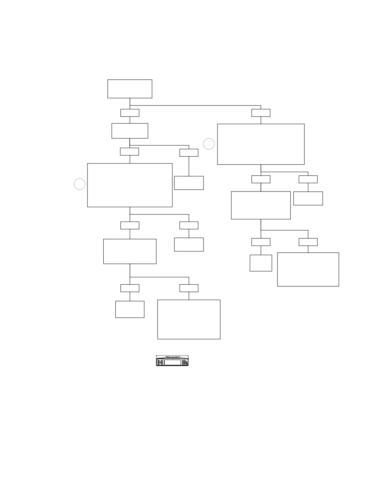
Front Speakers Open: DTC B2017
Is Optional Harley-
Davidson Amplifier
Installed?
YES
NO
Inspect amplifier
Disconnect Connector [27]. Install Breakout
fuse.
Box HD-47918 Leaving Radio Disconnected.
Is fuse good?
Measure Resistance
1
Between Terminals “16” and “17” (Left
Speaker) or Between Terminals “1” and “18”
YES
NO
(Right Speaker) on Breakout Box.
Is Resistance Greater Than 3 Ohms?
Disconnect Connector [149]. Install
Breakout Box HD-47918 to Amplifier
Harness Leaving Amplifier Disconnected.
YES
NO
Replace
1
Measure Resistance Between
amplifier fuse.
Terminals “7” and “14” (Left Speaker) or
Between Terminals “6” and “13” (Right
6130
Replace
Speaker) on Breakout Box.
Measure Resistance
Radio.
Is Resistance Greater Than 3 Ohms?
Across Speaker Terminals.
Is Resistance
6101
Greater Than 3 Ohms?
YES
NO
Replace
YES
NO
Measure Resistance
Amplifier.
Across Speaker Terminals.
Is Resistance
6107
Greater Than 3 Ohms?
On Harness From Radio to
Replace
Speaker, Locate and Repair
Speaker.
Open Between Terminal “16” or
“17” and Left Speaker, or
6605
Between Terminal “1” or “18”
and Right Speaker.
YES
NO
6532
Replace
On Harness From Amplifier
Speaker.
to Speaker, Locate and
Repair Open Between Terminal
6605
“7” or “14” and Left Speaker,
or Between Terminal “6” or “13”
and Right Speaker.
6117
Verify DTC is no longer present using radio
diagnostics. See RADIO DIAGNOSTICS. Confirm
proper operation with no DTCs.
fc00509_en
2008 Touring Diagnostics: Audio System 5-47
HOME
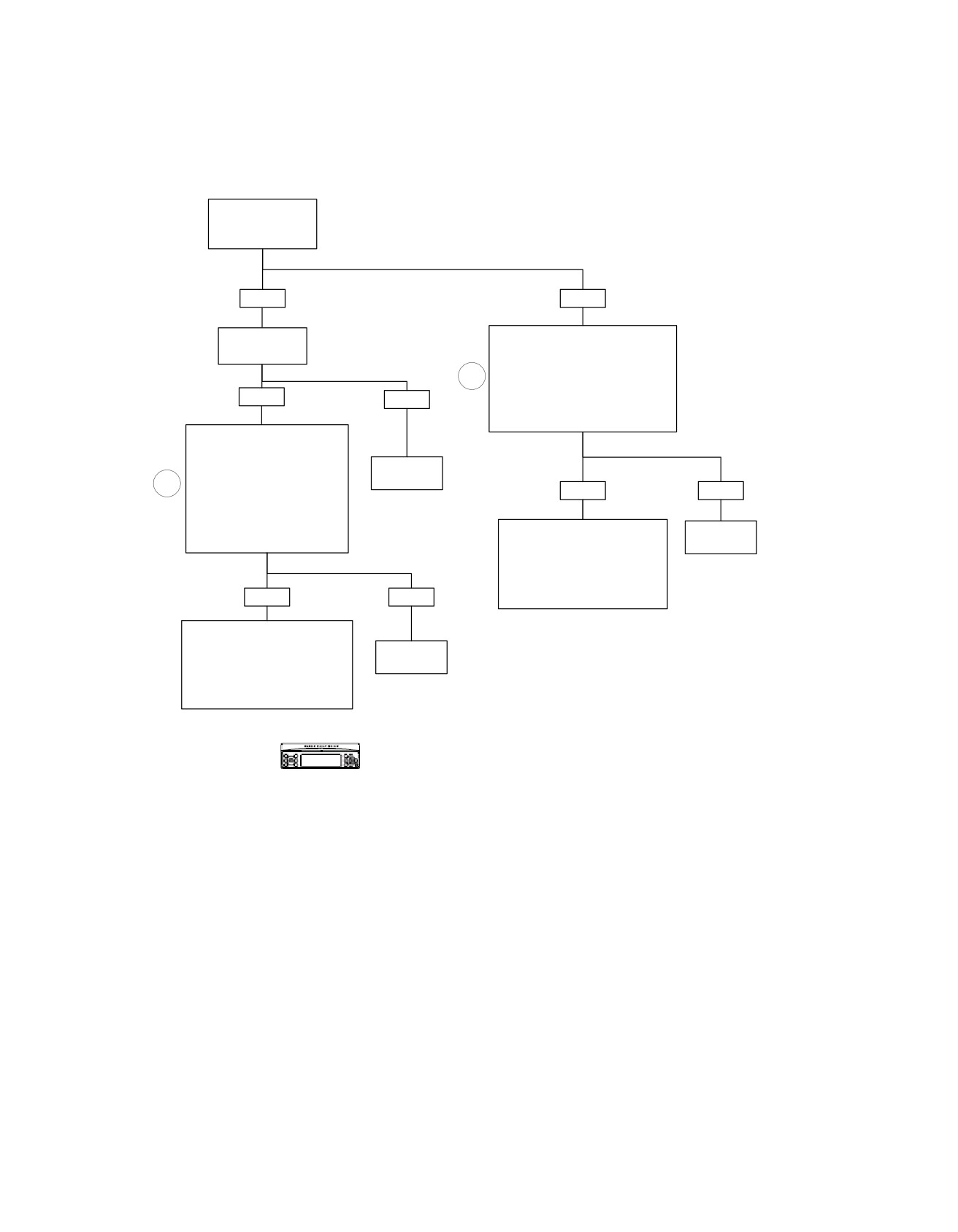
Front Speakers Shorted to Ground: DTC B2018
Is Optional Harley-
Davidson Amplifier
Installed?
YES
NO
Inspect amplifier
Disconnect Connector [27]. Install
fuse.
Breakout Box HD-47918 Leaving
Is fuse good?
Radio Disconnected. Using Breakout
Box, Measure Continuity to Ground
1
Between Terminals “16” and “17” (Left
YES
NO
Speaker) or Between Terminals “1” and
“18” (Right Speaker) and Ground.
Is Continuity Present?
Disconnect Connector [149].
Install Breakout Box HD-47918
to Amplifier Harness Leaving
Amplifier Disconnected. Using
Replace
amplifier fuse.
1
Breakout Box, Measure Continuity
YES
NO
to Ground Between Terminals
6130
“7” and “14” (Left Speaker) or
Between Terminals “6” and “13”
(Right Speaker) and Ground.
On Harness From Radio to
Replace
Is Continuity Present?
Speaker, Locate and Repair
Radio.
Short to Ground Between Terminal
6101
“16” or “17” (Left Speaker) or
Between Terminal “1” or “18” (Right
YES
NO
Speaker).
6531
On Harness From Amplifier to
Speaker, Locate and Repair
Replace
Short to Ground Between Terminal
Amplifier.
“7” or “14” (Left Speaker) or
Between Terminal “6” or “13” (Right
6107
Speaker).
6116
Verify DTC is no longer present using radio
diagnostics. See RADIO DIAGNOSTICS. Confirm
fc00510_en
proper operation with no DTCs.
5-48 2008 Touring Diagnostics: Audio System
HOME
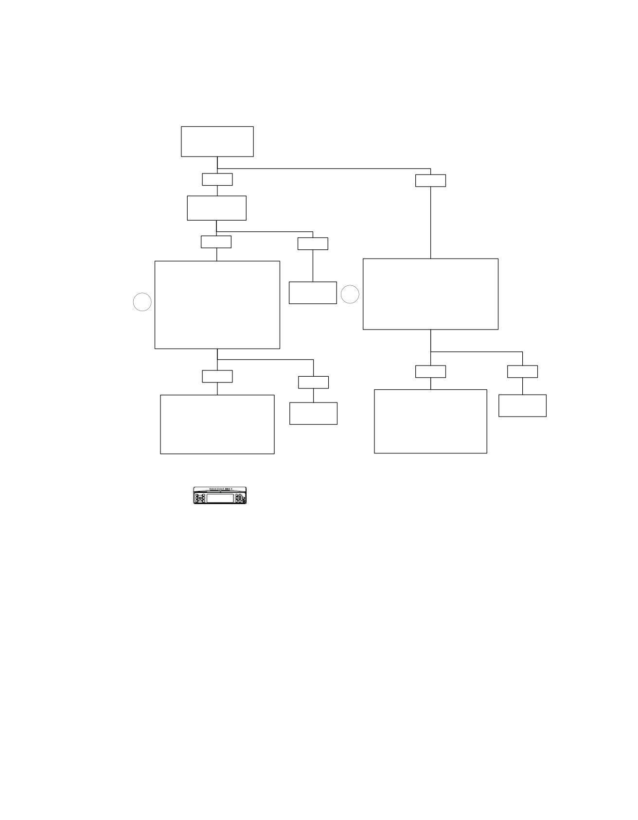
Front Speakers Shorted to Battery: DTC B2019
Is Optional Harley-
Davidson Amplifier
Installed?
YES
NO
Inspect amplifier
fuse.
Is fuse good?
YES
NO
Install Breakout Box HD-47918 to Harness
Disconnect Connector [149]. Install
Leaving Radio Disconnected. Turn
Breakout Box HD-47918 to Amplifier
Ignition ON. Measure Voltage Between
Harness Leaving Amplifier
Replace
Terminal “16” or “17” (Left
amplifier fuse.
1
Disconnected. Turn Ignition ON.
Speaker) and Ground, or Between
1
Measure Voltage Between Terminals “7”
Terminal “1” or “18” (Right Speaker) and
or “14” (Left Speaker) and Ground, or
6130
Ground on Breakout Box.
Between Terminals “6” or “13” (Right
Is Voltage Present?
Speaker) and Ground on Breakout Box.
Is Voltage Present ?
YES
NO
YES
NO
Disconnect Front Speaker.
Replace
Disconnect Front Speaker. Locate
Locate and Repair Short to
Replace
Radio.
and Repair Short to Voltage on
Voltage on Terminal “16” (W/O) or
Amplifier.
Terminal “7" (W/O) or Terminal “14”
Terminal “17” (LGN/W) on Left
6101
(LGN/W) on Left Speaker, or
6107
Speaker, or Terminal “18” (GY/R) or
Terminal “6” (GY/R) or Terminal “13”
Terminal “1” (LGN/BK) on Right
(LGN/BK) on Right Speaker.
Speaker.
6116
6531
Verify DTC is no longer present using radio
diagnostics. See RADIO DIAGNOSTICS. Confirm
proper operation with no DTCs.
fc00511_en
2008 Touring Diagnostics: Audio System 5-49
HOME
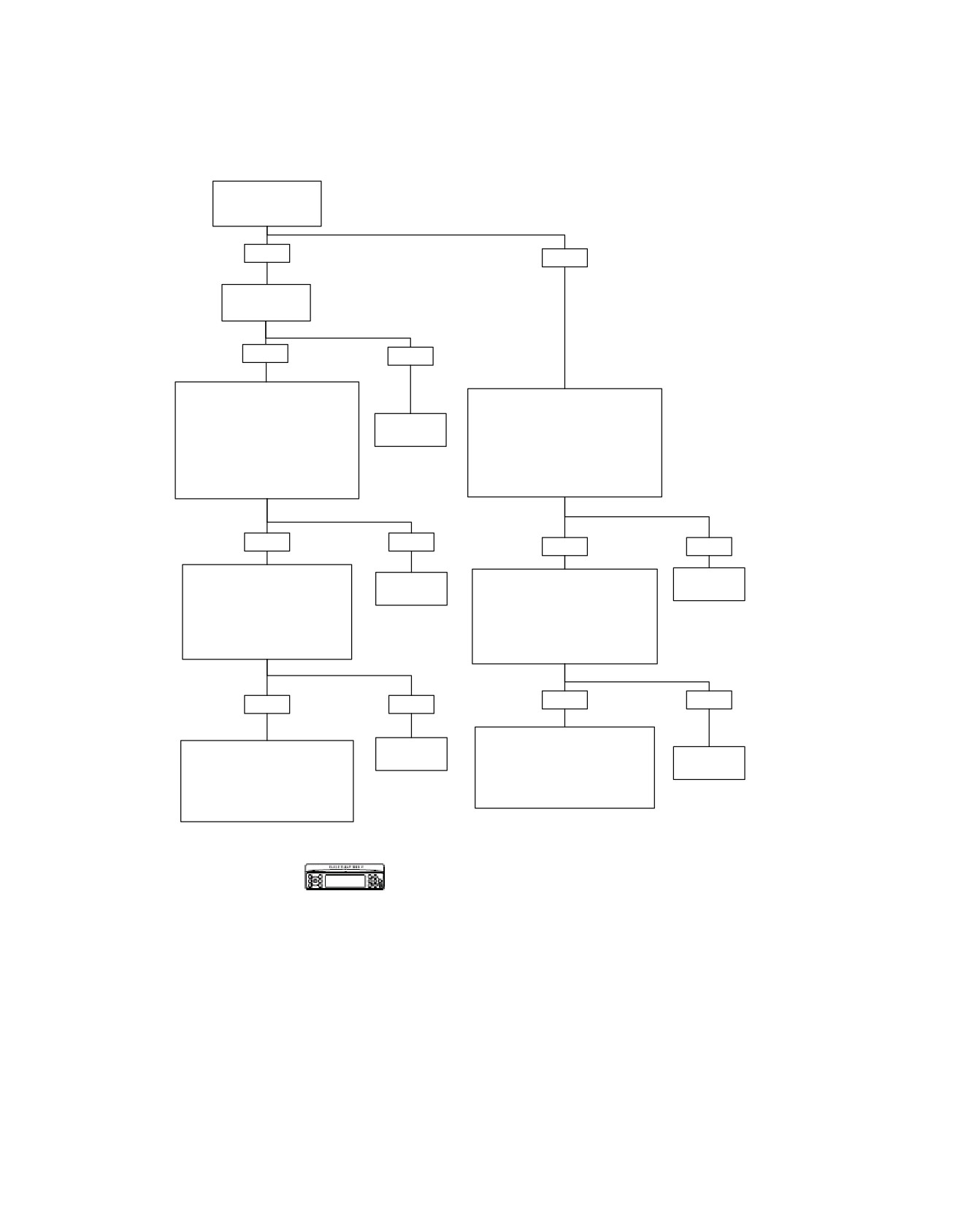
Rear Speakers Shorted: DTC B2020
Is Optional Harley-
Davidson Amplifier
Installed?
YES
NO
Inspect amplifier
fuse.
Is fuse good?
YES
NO
Disconnect Connector [149].
Install Breakout Box HD-47918 to
Disconnect Connector [28]. Install
Amplifier Harness Leaving Amplifier
Breakout Box HD-47918 Leaving
Replace
Radio Disconnected. Measure Resistance
Disconnected. Measure
amplifier fuse.
Between Terminals “2” and “25”
Resistance Between Terminals “22”
(Left Speaker) or Between
and “23” (Left Speaker) or Between
6130
Terminals “1” and “24” (Right
Terminals “8” and “15” (Right
Speaker) on Breakout Box.
Speaker) on Breakout Box.
Is Resistance Less Than One Ohm?
Is Resistance Less Than One Ohm?
YES
NO
YES
NO
Disconnect Speaker. Measure
Replace
Disconnect Speaker. Measure
Replace
Resistance Between Terminals
Amplifier.
Resistance Between Terminals “2”
Radio.
“22” and “23” (Left Speaker) or
and “25” (Left Speaker) or
6101
Between Terminals “8” and “15”
6107
Between Terminals “1” and “24”
(Right Speaker) on Breakout Box.
(Right Speaker) on Breakout Box.
Is Resistance Less Than One Ohm?
Is Resistance Less Than
One Ohm?
YES
NO
YES
NO
Locate and Repair Short
Locate and Repair Short
Replace
Between Terminals “2” and “25”
Speaker.
Replace
Between Terminals “22” and “23”
(Left Speaker) or Between
Speaker.
(Left Speaker) or Between Terminals
Terminals “1” and “24” (Right
6606
“8” and “15” (Right
Speaker) on Harness From
6606
Speaker) on Harness From
Radio to Speaker.
Amplifier to Speaker.
6560
6116
Verify DTC is no longer present using radio
diagnostics. See RADIO DIAGNOSTICS. Confirm
fc00512_en
proper operation with no DTCs.
5-50 2008 Touring Diagnostics: Audio System