Harley Davidson 2008 Touring Models. Electrical Diagnostics Manual - page 26
HOME
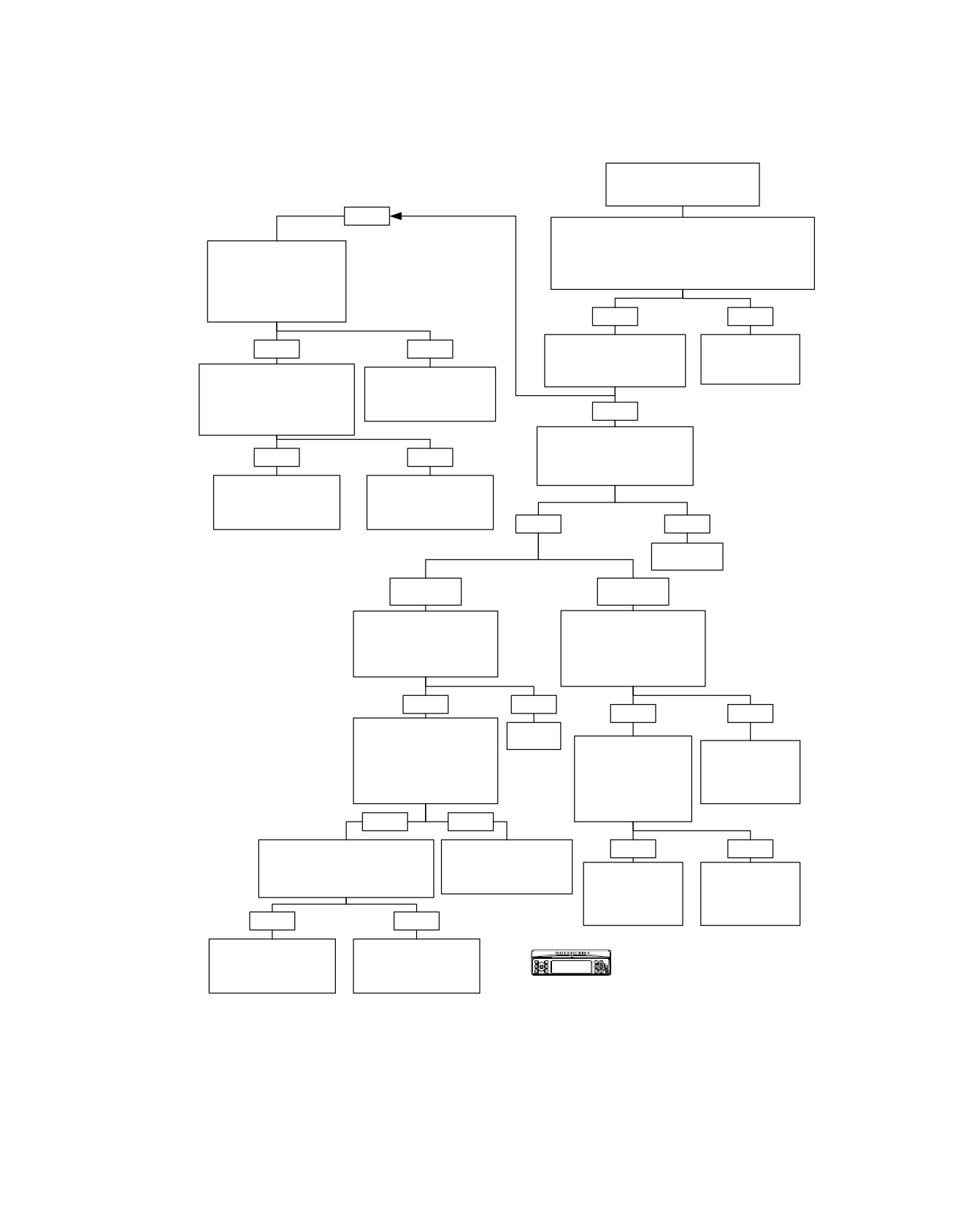
Headset Speakers Inoperative: Symptom 12 (Part 5 of 5)
From HEADSET
SPEAKERS INOPERATIVE:
Symptom 12 (Part 2 of 5).
NO
Measure Continuity Between Terminals:
“17” on HD-47918 [28] to Terminal “2” on Sidecar DIN,
Disconnect Sidecar Console
“15” on HD-47918 [28] to Terminal “5” on Sidecar DIN,
Connector [197]. Measure
“16” on HD-47918 [28] to Terminal “3” on Sidecar DIN.
Continuity Between Terminals
Is Continuity Present?
“17”, “15” and “16” on HD-
47918 [28].
Is Continuity Still Present?
YES
NO
Measure Continuity
Locate and Repair
YES
NO
Between Terminals “17”, “15”
Open Between
and “16” on HD-47918 [28].
Connector [28] and
Disconnect Connector
Locate and Repair
Is Continuity Present?
Sidecar DIN.
[53]. Measure Continuity
Short Between (Y/R), (Y/W)
6152
Between Terminals “17”, “15”
and (Y/BK) Wires in Sidecar
and “16” on HD-47918 [28].
Console Harness.
YES
Is Continuity Still Present?
6151
Measure Continuity Between
Terminals “17”, “15” and “16” on
YES
NO
HD-47918 [28] and Ground.
Is Continuity Present?
Locate and Repair
Locate and Repair
Short Between (GY/BK),
Short Between (GY/BK),
(GN/V) and (Y/BK) Wires
(GN/V) and (Y/BK Wires)
in Audio Harness.
in Sidecar Harness.
YES
NO
6151
6151
Replace
Radio.
6103
Terminal “17"
Terminals
Only.
“15” or “16”.
Measure Voltage Between
Disconnect Sidecar Console
Terminals “15” or “16” on HD-
Connector [197]. Measure
47918 [28] and Ground.
Continuity to Ground at
Is Voltage Greater Than 9V
Terminals “15” and “16” on HD-
Present?
47918 [28].
Is Continuity Still Present?
YES
NO
YES
NO
Disconnect Sidecar Console
Replace
Connector [197]. Measure
Radio.
Disconnect Connector
Voltage at Terminals “15” (+)
Locate and Repair
[53]. Measure Continuity
and “16” (+) on HD-47918 [28]
6103
Short to Ground
to Ground at Terminals
to Ground (-).
on (Y/R) or (Y/W)
“15” and “16” on HD-
Is Voltage Greater Than 9V
Wires in Sidecar
47918 [28].
Present?
Console Harness.
Is Continuity Still
Present?
6151
YES
NO
Disconnect Connector [53]. Measure
Locate and Repair Short
YES
NO
Voltage at Terminals “15” (+) and “16”
to Voltage on (Y/R) or (Y/W)
Locate and Repair
Locate and Repair
(+) on HD-47918 [28] to Ground (-).
Wires in Sidecar Console
Short to Ground on
Short to Ground on
Is Voltage Greater Than 9V Present?
Harness.
(GY/BK) or (GN/V)
(GY/BK) or (GN/V)
6151
Wires in Ultra
Wires in Sidecar
YES
NO
Overlay Harness.
Harness.
6151
6151
Locate and Repair Short
Locate and Repair Short
to Voltage on (GY/BK) or
to Voltage on (GY/BK) or
Confirm proper operation with no DTCs.
(GN/V) Wires in Audio
(GN/V) Wires in Sidecar
Harness.
Harness.
fc00551_en
6151
6151
2008 Touring Diagnostics: Audio System 5-111
HOME
(BK)
em00199
[28B]
CAV
CIR
DESCRIPTION
1
BK
MIC IN SHARED (-)
2
Y/BK
HDSET SPKR SHARED (-)
For all
3
GY/Y
RT REAR HDSET SPKR (+)
5
GY/O
4
R
REAR MIC (+)
P&A ultra ACC
except
6
Y/W
5
GY/O
LFT REAR HDSET SPKR (+)
harness
FLHTCU
6
7
[76A]
TAB
SHIELD
MIC SHARED SHIELD
To
[76C]
[76D]
DIN on ultra
ultra
[76B]
radio
[28A]
Passenger
Y/BK
2
2
2
Headset
GY/Y
3
3
3
15
GN/V
16
GY/BK
GY/O
5
5
5
17
Y/BK
Radio Pinouts
RT rear speaker (+) - 1
[28A]
LFT rear speaker (+) - 2
(BK)
CB/GMRS audio (+) - 3
HFM audio (+) - 4
LFT rear HDSET SPKR (+) - 5
LFT FRT HDSET SPKR (+) - 6
28
GY/Y
LFT XM - 7
29
Y/R
LFT CD changer - 8
FRT MIC (+) - 9
Rear MIC (+) - 10
RR2 (RR CNTL matrix) - 11
RC4 (RR CNTL matrix) - 12
CAN (+) - 13
[197B] [197A]
CAN (-) - 14
LFT SDCAR HDSET SPKR (+) - 15
RT SDCAR HDSET SPKR (+) - 16
Sidecar
HDSET SPKR shared (-) - 17
XM (-) - 18
[53A]
2
3
7 89
Headset
Y/BK
7
7
Y/BK
Y/BK
2
CD changer (-) - 19
(BK)
MIC shared (-) - 20
[53D]
2
3
789
GY/BK
8
8
Y/R
Y/R
3
MIC shared shield - 21
MIC sum out (-) - 22
GN/V
9
9
Y/W
Y/W
5
RR1 (RR CNTL matrix) - 23
RT rear SPKR (-) - 24
LFT rear SPKR (-) - 25
CB/GMRS audio (-) - 26
HFM audio (-) - 27
RT rear HDSET SPKR (+) - 28
RT FRT HDSET SPKR (+) - 29
Ultra
RT XM - 30
Sidecar
CAV
CIR
DESCRIPTION
RT CD changer - 31
1
BK
MIC IN SHARED (-)
SDCAR MIC in (+) - 32
Harness
2
Y/BK
HDSET SPKR SHARED (-)
MIC SUM out (+) - 33
Ultra
RR0 (RR CNTL matrix) - 34
88403-06
3
Y/R
RT HDSET SPKR (+)
RC3 (RR CNTL matrix) - 35
Sidecar
4
R
FRT MIC (+)
[53C]
78 9
Console
5
Y/W
LFT HDSET SPKR (+)
(BK)
6
[53B]
78 9
7
TAB
SHIELD
MIC SHARED SHIELD
Driver
CAV
CIR
DESCRIPTION
1
BK
MIC IN SHARED (-)
Headset
2
Y/BK
HDSET SPKR SHARED (-)
3
Y/R
RT FRT HDSET SPKR (+)
4
R
FRT MIC (+)
5
Y/W
LFT FRT HDSET SPKR (+)
6
7
BE/Y
PUSH-TO-TALK
TAB
SHIELD
MIC SHARED SHIELD
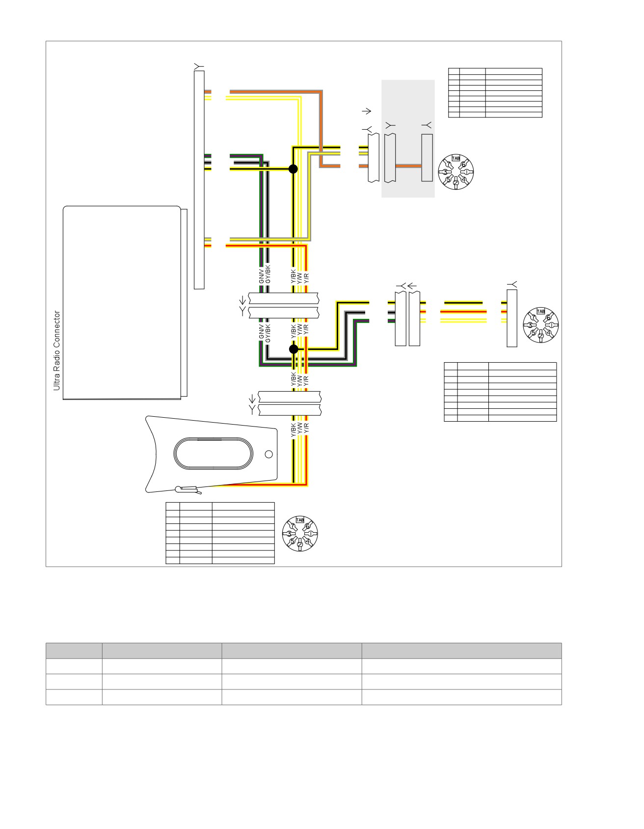
Figure 5-37. Headset Speaker Circuit
Table 5-39. FLHT/C/U Wire Harness Connectors
NO.
DESCRIPTION
TYPE
LOCATION
[28]
Radio
35-Place Amp
Inner fairing - back of radio (left side)
[53]
Console pod
12-Place Mini-Deutsch
Rear of battery box (under seat)
[197]
Sidecar console
12-Place Mini-Deutsch
Inside sidecar console
5-112 2008 Touring Diagnostics: Audio System
HOME
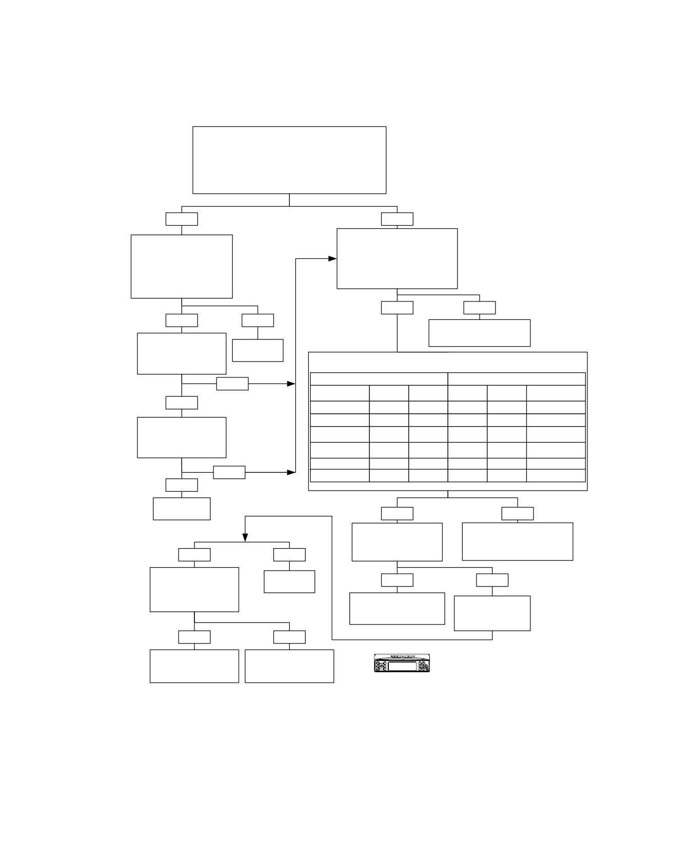
No or Low Audio From Microphones: Symptom 13 (Part 1 of 4)
Place a Known Working Headset in Rider DIN Connector.
Turn Intercom ON, Set VOX Threshold to OPEN and Set
Intercom Volume to Mid Level.
Do You Hear Audio in the Headset Earpiece When
Speaking?
NOTE:
If Intercom is not installed, use PTT when speaking.
YES
NO
Remove Microphones From DIN
Replace Cable on Bad
Connectors. Measure DC Voltage
Headset or Replace Hand
Between Terminal “4” (+ Probe)
Held Microphone. Reinstall
and Terminal “1” (- Probe) of Each
on Rider DIN Connector.
DIN Connector.
Do You Hear Audio in the
Is the Voltage Between +7.5 and
Headset Earpiece When
+8.5 Volts?
Speaking?
YES
NO
YES
NO
Go to NO OR LOW AUDIO
FROM MICROPHONES:
Test Passenger and
Symptom 13 (Part 4 of 4).
Sidecar (If Equipped).
Replace
Headset.
Do All Inputs Work With
Measure Continuity Between Terminals as Follows.
Intercom?
Is Continuity Present?
FROM
TO
NO
Radio Terminal
Radio Terminal
Connector
Terminal
Terminal
Connector
Name
Name
YES
Mic Sum Out (+)
[28]
“33”
“1”
[184B]
CB- Mic (+)
Mic Sum (-)
[28]
“22”
“2”
[184B]
CB- Mic (-)
Test Other Microphone
Hands Free
Driven Sources (CB and
Mic Sum Out (+)
[28]
“33”
“11”
[187B]
Module - Mic (+)
Hands Free Phone).
Hands Free
Are All Sources Working?
Mic Sum (-)
[28]
“22”
“12”
[187B]
Module - Mic (-)
Mic Sum Out (+)
[28]
“33”
N/A
N/A
Intercom
NO
Mic Sum (-)
[28]
“33”
N/A
N/A
Intercom
YES
System
OK.
YES
NO
Measure Continuity
Locate and Repair Open on (R) or
Between Terminals
(BK) Wires Between Connectors
“33” and “22”.
[184B/D] or [187B] and Connector
YES
NO
Is Continuity Present?
[28B].
6153
Measure Voltage
Between Terminal
Replace
YES
NO
Radio.
“33” and Ground.
Is Voltage Greater
6106
Go to NO OR LOW AUDIO
Measure Continuity
Than 9 Volts?
FROM MICROPHONES:
Between Terminal
Symptom 13 (Part 2 of 4).
“22” and Ground.
Is Continuity Present?
YES
NO
Go to NO OR LOW AUDIO
Go to NO OR LOW AUDIO
Confirm proper operation with no DTCs.
FROM MICROPHONES:
FROM MICROPHONES:
Symptom 13 (Part 3 of 4).
Symptom 13 (Part 2 of 4).
fc00552_en
2008 Touring Diagnostics: Audio System 5-113
HOME
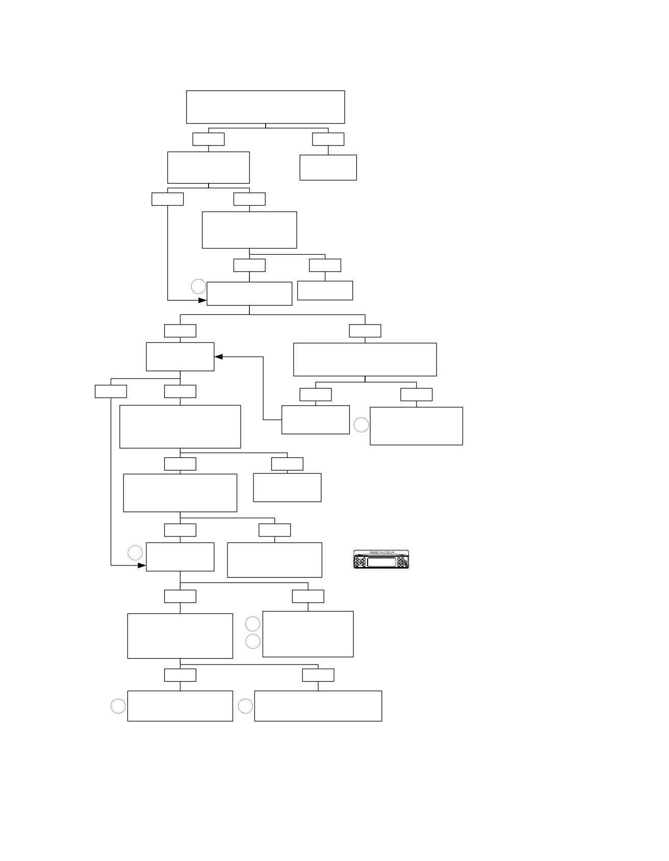
No or Low Audio From Microphones: Symptom 13 (Part 2 of 4)
Disconnect Connector [28A] From Breakout Box.
Is There Still Continuity Between Terminals “33”
and “22” on Connector [28B]?
YES
NO
Reinstall Connector
Replace
[28A] to Breakout Box.
Radio.
Is CB Installed?
6106
NO
YES
Remove CB Module. Is
There Still Continuity
Between Terminals “33” and
“22” on Connector [28B]?
YES
NO
7
Replace CB
Is CVO CB/XM YHarness
Module.
70172-06 Installed?
6625
NO
YES
Is Hands Free
Disconnect Connector [184C] From [184B].
Phone Module
Is There Still Continuity Between Terminals
Installed?
“33” and “22” on Connector [28B]?
NO
YES
YES
NO
Remove Hands Free Phone Module
Reconnect
Locate and Repair Short
at Connector [194].
Connector
in (CB/XM) Y-Harness
Is There Still Continuity Between
[184C] to [184B].
7
70172-06 Between (R) and
Terminals “33” and “22” on Connector
(BK) Wires.
[28B]?
6153
YES
NO
Remove Connector [187A].
Replace Hands
Is There Still Continuity Between
Free Phone
Terminals “33” and “22” on
Module.
Connector [28B]?
YES
NO
Is P&A Ultra Overlay
Locate and Repair Short in
8
Harness 70164-
Hands Free Phone Module
06 Installed?
Harness 76467-06
Between (R) and (BK) Wires.
Confirm proper operation with no DTCs.
YES
NO
Disconnect Connector
Locate and Repair Short
9
in P&A Non-Ultra Harness
[184C] From [184B].
Is There Still Continuity Between
70169-06 or Audio Harness
Terminals “33” and “22” on
10
70160-06 Between (R) and
Connector [28B]?
(BK) Wires.
6154
YES
NO
Locate and Repair Short in
Locate and Repair Short in P&A Ultra
fc00553_en
10
Audio Harness 70160-06
8
Overlay Harness 70164-06 Between
Between (R) and (BK) Wires.
(R) and (BK) Wires.
6154
6154
5-114 2008 Touring Diagnostics: Audio System
HOME
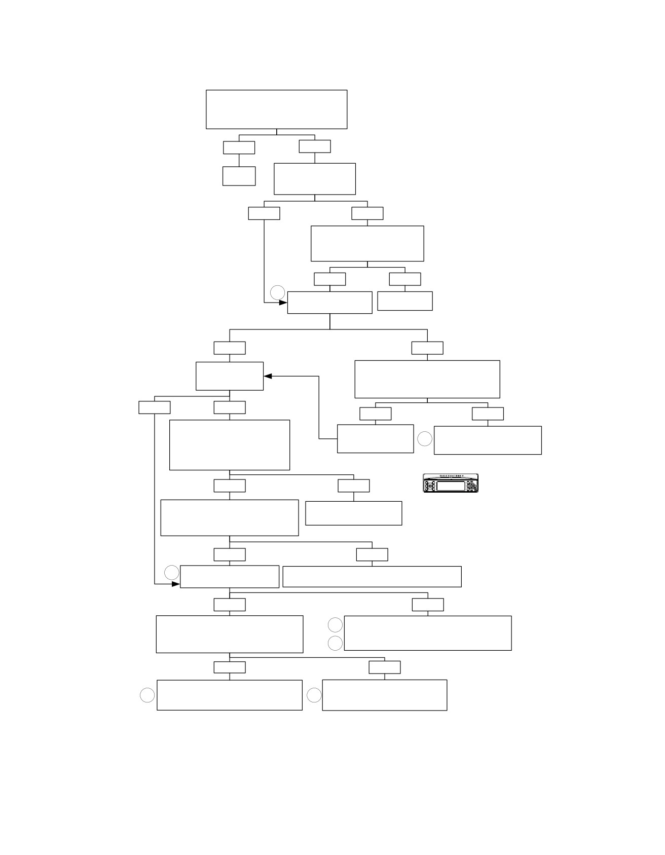
No or Low Audio From Microphones: Symptom 13 (Part 3 of 4)
Disconnect Connector [28A] From Breakout
Box. Measure Voltage Between Terminals
“33” and “22” on Connector [28B].
Is it Greater Than 9 Volts?
YES
NO
Replace
Reinstall Connector
Radio.
[28A] to Breakout Box.
Is CB Installed?
6106
NO
YES
Remove CB Module. Measure
Voltage Between Terminals “33”
and “22” on Connector [28B].
Is it Greater Than 9 Volts?
YES
NO
7
Is CVO CB/XM YHarness
Replace
70172-06 Installed?
CB Module.
6625
NO
YES
Is Hands Free
Disconnect Connector [184C] From [184B].
Phone Module
Measure Voltage Between Terminals “33”
Installed?
and “22” on Connector [28B].
Is it Greater Than 9 Volts?
YES
NO
YES
NO
Remove Hands Free Phone
Reconnect Connector
Locate and Repair Short to
Module at Connector [194].
7
Voltage in CB/XM Y-Harness
Measure Voltage Between Terminals
[184C] to [184B].
70172-06 on (R) or (++R) Wires.
“33” and “22” on Connector [28B].
Is it Greater Than 9 Volts?
6155
YES
NO
Remove Connector [187A]. Measure
Replace Hands Free Phone
Confirm proper operation with no DTCs.
Voltage Between Terminals “33” and “22”
Module.
on Connector [28B].
Is it Greater Than 9 Volts?
YES
NO
8
Is P&A Ultra Overlay Harness
Locate and Repair Short in Hands Free Phone Module
70164-06 Installed?
Harness 76467-06 Between (R) and (++R) Wires.
6155
YES
NO
Disconnect Connector [184C] From [184B].
9
Locate and Repair Short to Voltage in P&A Non-Ultra
Measure Voltage Between Terminals “33” and
Harness 70169-06 or Audio Harness 70160-06
“22” on Connector [28B].
10
Between (R) and (++R) Wires.
Is it Greater Than 9 Volts?
6155
YES
NO
Locate and Repair Short to Voltage in
Locate and Repair Short to Voltage in
10
Audio Harness 70160-06 Between (R) and
8
P&A Ultra Overlay Harness 70164-06
(++R) Wires.
Between (R) and (++R) Wires.
fc00554_en
6155
6155
2008 Touring Diagnostics: Audio System 5-115
HOME
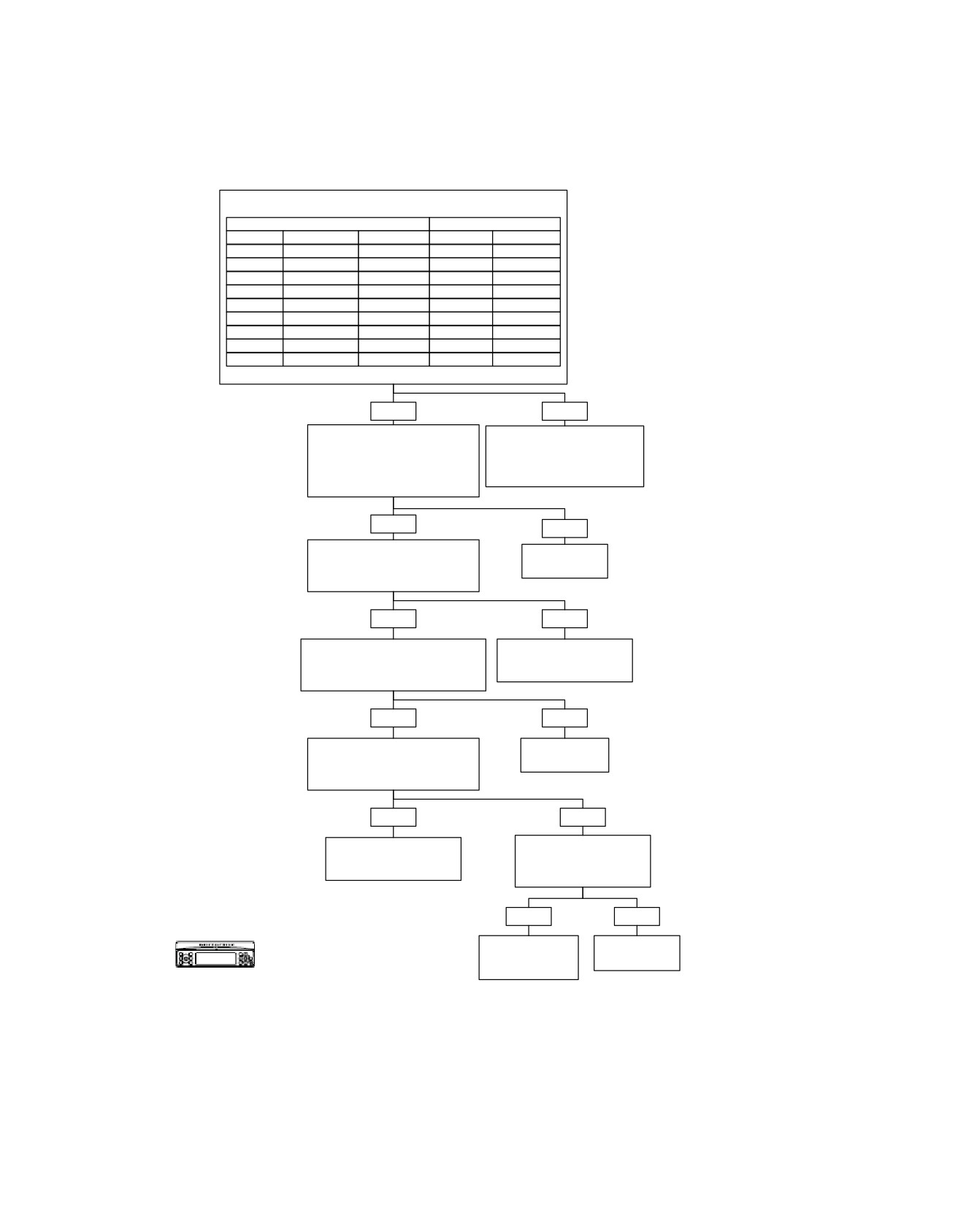
No or Low Audio From Microphones: Symptom 13 (Part 4 of 4)
Remove All Microphones/Headsets. Measure Continuity
Between Terminals as Follows.
FROM
FROM
Function
Connector
Terminal
Connector
Terminal
Shield
Rider DIN
Tab
[28B]
“21”
Mic (+)
Rider DIN
“4”
[28B]
“9”
Mic (-)
Rider DIN
“1”
[28B]
“20”
Shield
Passenger DIN
Tab
[28B]
“21”
Mic (+)
Passenger DIN
“4”
[28B]
“10”
Mic (-)
Passenger DIN
“1”
[28B]
“20”
Shield
Sidecar DIN
Tab
[28B]
“21”
Mic (+)
Sidecar DIN
“4”
[28B]
“32”
Mic (-)
Sidecar DIN
“1”
[28B]
“20”
Is Continuity Present?
YES
NO
Install Breakout Box HD-44608.
Locate and Repair Open
Measure Continuity Between
on (R), (BK) and Shield
Terminals “20” (Mic Shared -) and
Wires Between DIN Connector
“21” (Mic Shared Shield) on
and Connector
Connector [28B] and Ground.
[28B].
Is Continuity Present?
6153
YES
NO
Measure Continuity Between
Replace
Terminals “9”, “10” and “32” (Mic +)
Radio.
on Connector [28B] and Ground.
Is Continuity Present?
6106
YES
NO
Disconnect Connector [28B] From
Locate and Repair Short
Breakout Box. Measure Voltage at
to Ground on (R) Wire
Terminals “9”, “10” and “32”.
Showing Continuity.
Is Voltage Between 7.5 and 8.5 Volts?
6155
YES
NO
Reconnect Connector [28B] to
Replace
Breakout Box. Measure Voltage at
Radio.
Terminals “9”, “10” and “32”.
Is Voltage Greater Than 8.5 Volts?
6106
YES
NO
Were You Directed to
Locate and Repair Short
These Charts From NO
to Battery on (R) Wire
OR LOW AUDIO TO
Showing Short to Voltage.
HAND FREE MODULE?
6155
YES
NO
Replace Hands
No Trouble
Confirm proper operation with no DTCs.
Free Phone
Found.
Module.
fc00555_en
5-116 2008 Touring Diagnostics: Audio System
HOME
em00200
For all
P&A ultra ACC
except
harness
FLHTCU
[76A]
9
++R
Din on ultra
[76C]
[76D]
10
R
[76B]
BK
1
1
1
Passenger
To
2
2
Headset
ultra
3
3
R
4
4
4
CAV
CIR
DESCRIPTION
radio
5
5
1
BK
MIC IN SHARED (-)
[28A]
2
Y/BK
HDSET SPKR SHARED (-)
3
GY/Y
RT REAR HDSET SPKR (+)
SHIELD
TAB
TAB
TAB
4
R
REAR MIC (+)
20
BK
5
GY/O
LFT REAR HDSET SPKR (+)
21
BK
6
22
++BK
7
TAB
SHIELD
MIC SHARED SHIELD
++R
1
++BK
2
32
++W
33
++R
Future
[186B]
[28B]
(BK)
++R
1
1
++R
R
1
++BK
2
2
++BK
BK
2
CB Module
C.B.
[184B]
[184C]
[184D]
P/N 70169-06 - P&A non-ultra
harness replaces P/N's
70160-06 & 70164-06 and is
represented when this
1 2
[187B]
connector does not exist.
For all except FLHTCUI
1 2
[187A]
Hands
Free
++R
45
Module
++BK
46
[53A]
1
10 11 12
(BK)
[53D]
1
10 11 12
[194B]
Ultra
Sidecar
Sidecar
[197B] [197A]
BK
1
Harness
Headset
88403-06
R
4
W
10
10
R
BK
11
11
BK
SHIELD
12
12
SHIELD
SHIELD
TAB
[53C]
10 11 12
(BK)
[53B]
10 11 12
Ultra
Sidecar
CAV
CIR
DESCRIPTION
Console
1
BK
MIC IN SHARED (-)
2
Y/BK
HDSET SPKR SHARED (-)
3
Y/R
RT HDSET SPKR (+)
4
R
FRT MIC (+)
5
Y/W
LFT HDSET SPKR (+)
6
7
TAB
SHIELD
MIC SHARED SHIELD
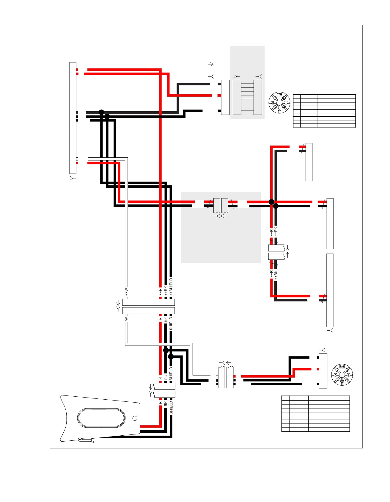
Figure 5-38. Microphone Audio Input Circuit
2008 Touring Diagnostics: Audio System 5-117
HOME
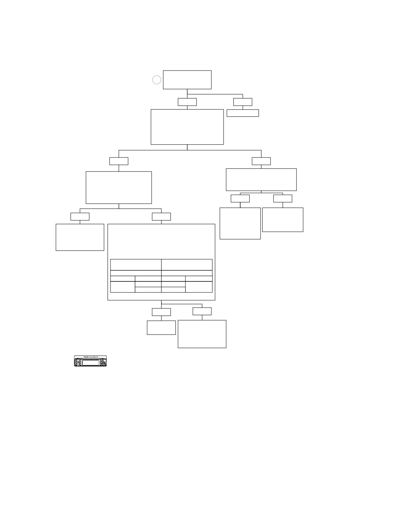
No or Low Audio with High Output Amplifier: Symptom 14 (Part 1 of 2)
Inspect fuse to
11
amplifier.
Is fuse OK?
YES
NO
Disconnect Connector [149].
Replace fuse.
Install Breakout Box HD-44608.
6130
Measure Voltage Between Terminals
“3” and “4” (+) and Between Terminals
“20” and “21” (-) on Breakout Box HD-
44608
(Black).
Is Battery Voltage Present?
YES
NO
Measure Resistance Between
Measure Voltage Between
Terminals “20” and “21” to Ground
(Y/O) Terminal “1” (+) and (Y/
on Breakout Box.
V) Terminal “2” (-) on Breakout
Is Resistance Less Than One Ohm?
Box HD-44608 (Black). Voltage
Should be 5V.
Is It?
YES
NO
Locate and Repair
Locate and Repair
YES
NO
Open on (R) Wire
Open on (BK) Wire
Between Connector
Between Connector
Go to NO OR LOW
[149] and fuse or
[149] and Ground.
Disconnect Connector [28]. Install Breakout Box
Between Fuse and
AUDIO WITH HIGH
HD-47918 Leaving Radio Disconnected. Install
Battery.
6131
OUTPUT AMPLIFIER:
Breakout Box HD-44608 to Harness Leaving
Symptom 14
6131
Amplifier Disconnected. Measure Continuity
(Part 2 of 2).
Between Radio Breakout Box [28] Interconnect
and Amplifier Breakout Box (Black Label) as Follows:
Breakout Box
Breakout Box
HD-47918
HD-44608
Terminal
Terminal
Connector
Terminal
Terminal
Connector
“13”
“1”
[28]
[149]
“14”
“2”
Is Resistance Less Than One Ohm?
YES
NO
Replace
Locate and Repair
Radio.
Open on (Y/O) or (Y/V)
Wire Between
6104
Connectors [149B]
and [28B].
6128
Confirm proper operation with no DTCs.
fc00556_en
5-118 2008 Touring Diagnostics: Audio System
HOME
em00201
(BK)
[28B]
To
ultra
radio
[28A]
13
14
5
5
4
4
Right
Rear
Speaker
[36A] [36D]
[6B] [6A]
[27B]
1
Left
Rear
Speaker
[37A] [37D]
To radio
[27A]
(BK)
Battery +
30A
[149B]
16
1
17
2
18
3
4
6
7
8
[34B] [34C]
11
12
Right
13
Front
14
Speaker
15
[35B] [35C]
[34A] [34D]
18
19
20
21
22
23
Left
High Output
Front
Amplifier
Speaker
[35A] [35D]
Ground Stud
(Right)
Figure 5-39. Front/Rear Speaker Circuits with Amplifier
2008 Touring Diagnostics: Audio System 5-119

HOME
Table 5-40. FLHT/C/U Wire Harness Connectors
NO.
DESCRIPTION
TYPE
LOCATION
[6]
Audio to interconnect har-
6-Place Deutsch (Black)
Inner fairing - left side of radio
ness
[27]
Radio
23-Place Amp
Inner fairing - back of radio (right side)
[28]
Radio
35-Place Amp
Inner fairing - back of radio (left side)
[34]
Front right speaker
Spade contacts
Inner fairing - back of right speaker
[35]
Front left speaker
Spade contacts
Inner fairing - back of left speaker
[36]
Rear right speaker
Spade contacts
Inside speaker box
[37]
Rear left speaker
Spade contacts
Inside speaker box
[149]
High output amplifier
23-Place Amp
Under luggage rack (right side)
5-120 2008 Touring Diagnostics: Audio System
HOME
No or Low Audio with High Output Amplifier: Symptom 14 (Part 2 of 2)
From NO OR LOW AUDIO WITH HIGH OUTPUT
AMPLIFIER: Symptom 13 (Part 1 of 2).
Disconnect Connector [27]. Install Breakout Box HD-47918 Leaving
Radio Disconnected. Install Breakout Box HD-44608 to Harness
Leaving Amplifier Disconnected. Measure Continuity Between Radio
Breakout Box [27] Interconnect and Amplifier Breakout Box (Black
Label) as Follows:
Breakout Box
Breakout Box
HD-47918
HD-44608
Terminal
Terminal
4
Connector
Terminal
Terminal
Connector
Left Speaker
“16”
“18”
[27]
[149]
“17”
“11”
Right Speaker
“18”
“19”
[27]
[149]
“1”
“12”
Is Resistance Less Than One Ohm?
YES
NO
Measure Continuity Between
Locate and Repair Open
Terminals “16” and “17” (Left
Between Connectors [27B]
Speaker) or Between Terminals
and [149B].
“18” and “1” (Right Speaker) on
Breakout Box [27] Interconnect.
6117
Is Continuity Present?
YES
NO
Locate and Repair Short in
Measure Continuity to Ground at
Harness Between Terminals
Terminals “16” and “17” (Left
“16” and “17” (Left Speaker) or
Speaker) or Between Terminals
Between Terminals “18” and
“18” and “1” (Right Speaker) on
“1” (Right Speaker) in Harness
Breakout Box [27] Interconnect.
From Amplifier [149B] to Radio
Is Continuity Present?
[27B].
6116
YES
NO
Locate and Repair Short to
Ground on Terminals “16” (W/O) or
Disconnect Breakout Box From
“17” (LGN/W) (Left Speaker) or on
Radio and Connect Connector
Terminals “18” (GY/R) or “1” (LGN/
[27]. Measure Voltage to Ground
BK) (Right Speaker) in Harness
at Amplifier Breakout Box
From Amplifier to Radio [27B].
(Black), Left Speaker Terminals “18” or
“11”, or Right Speaker Terminals
6116
“19” or “12”.
Less Than
Greater Than
4-8V?
4V?
8V?
Replace
Replace
Locate and Repair Short to
Radio.
Amplifier.
Voltage on Terminals “18”
6104
6110
(GY/R) or 1 (LGN/BK)
(Right Speaker) or on “16”
(W/O) or “17” (LGN/W)
(Left Speaker) in Harness
From Amplifier
Confirm proper operation with no DTCs.
to Radio.
6116
fc00557_en
2008 Touring Diagnostics: Audio System 5-121
HOME
No or Low Audio from XM or XM Inoperative: Symptom 15 (Part 1 of 2)
Locate Vehicle in “Open
Area” with Line of Site to
NOTE
Southern Sky.
XM Available in U.S. and
Does XM Icon Appear on
Canada Only.
Radio Display When
Moding Through Bands
With Two or More Signal
Bars Present on Display?
YES
NO
Install Breakout Box HD-42682 and Adapters HD-45325 to
Does “Check Antenna” or
Connector [185]. With the Ignition Switch Turned to IGN
“No Signal” Appear on
(Not Running) Measure Voltage at Breakout Box (Black)
Radio Display?
Between Terminals “9” (+) and “10” (-).
Is Battery Voltage Present?
YES
NO
YES
NO
Disconnect Connector [28].
Go to XM, NO
Install Breakout Box HD-
OR
Measure Voltage Between
Measure Resistance at
47918. Measure AC Voltage
INTERMITTENT
Breakout Box Terminals
Breakout Box Between
on Breakout Box [28],
RECEPTION:
“11” (-) and “12” (+).
Terminals “10” to Ground.
Between Terminals “30” and
Symptom 16.
Voltage Should be 4-6 V.
Is Resistance Less Than
“18” (Right Channel) and also
Is It?
One Ohm?
4
Between Terminals “7” and
“18” (Left Channel).
Is Varying AC Voltage (0-1.5
YES
NO
YES
NO
VAC) Present While XM is
Active?
Connect 35-pin connector
Locate and
Locate and
Inspect XM Pigtail and
HD-47918 Breakout Box to
Repair Open
Repair Open
Connector For Loose or
Radio and Harness in Fairing.
on (R/O) Wire
on (BK/GN) Wire
Damaged Connections.
Measure Continuity Between
Between
Between
Was Problem Found?
Terminal “11” on HD-42682
Connector
Connector
(Black) and Terminal “13” on
[185B]
[185B] and
YES
NO
YES
NO
4
HD-47918 [28] and also
and Radio
Ground.
Between Terminal “12” on HD-
Memory Fuse.
6129
Replace
Repair
Replace
42682
(Black) and Terminal
6129
Radio.
Connection
XM Module.
“14” on HD-47918 [28].
or Wiring.
Is Continuity Present?
6101
6126
6126
YES
NO
Connect 35-pin connector HD-
Replace
Locate and Repair
47918 Breakout Box to Radio and
Radio.
Open on (Y/O) or
(Y/V) Wire Between
Harness in Fairing. Measure Continuity
6101
Connectors [185B]
Between Terminal “8” on
and [28B].
Connector [185B] and Terminal
“18” on HD-47918 [28], Between
6128
Terminal “6” on Connector [185B] and
Terminal “30” on HD-47918 [28] and
also Between Terminal “7” on [185B]
and Terminal “7” on HD-47918 [28].
Is Continuity Present?
YES
NO
Locate and Repair
Go to XM, NO
Open on (R), (W) or
OR INTERMITTENT
(BK) Wire Between
RECEPTION:
Connectors [185B]
Symptom 16.
and [28B].
fc00558_en
Confirm proper operation with no DTCs.
6158
5-122 2008 Touring Diagnostics: Audio System
HOME
No or Low Audio from XM or XM Inoperative: Symptom 15 (Part 2 of 2)
From NO OR LOW
AUDIO FROM XM OR
XM INOPERATIVE:
NOTE:
Symptom 15 (Part 1 of 2).
XM Available in U.S. and
Canada Only.
Measure Continuity
Between Terminals “18”, “30”
and “7“ on HD-47918 [28].
Is Continuity Present?
YES
NO
Locate and Repair
Measure Continuity
Short Between (R), (W)
Between Terminals “18”, “30”
or (BK) Wires Between
and “7” on HD-47918 [28]
Connectors [185B]
and Ground.
and [28B].
Is Continuity Present?
6157
YES
NO
Measure Voltage Between
Locate and Repair
Terminals “18”, “30” and “7”
Short to Ground on
on HD-47918 [28] and
(R), (W) or (BK) Wires
Ground.
Between Connectors
Is Voltage Greater Than 8 V
[185B] and [28B].
Present?
6157
YES
NO
Locate and Repair
Short to Voltage on (R),
Replace
(W) or (BK) Wires
XM Module.
Between Connectors
[185B] and [28B].
6128
6157
Confirm proper operation with no DTCs.
fc00559_en
2008 Touring Diagnostics: Audio System 5-123
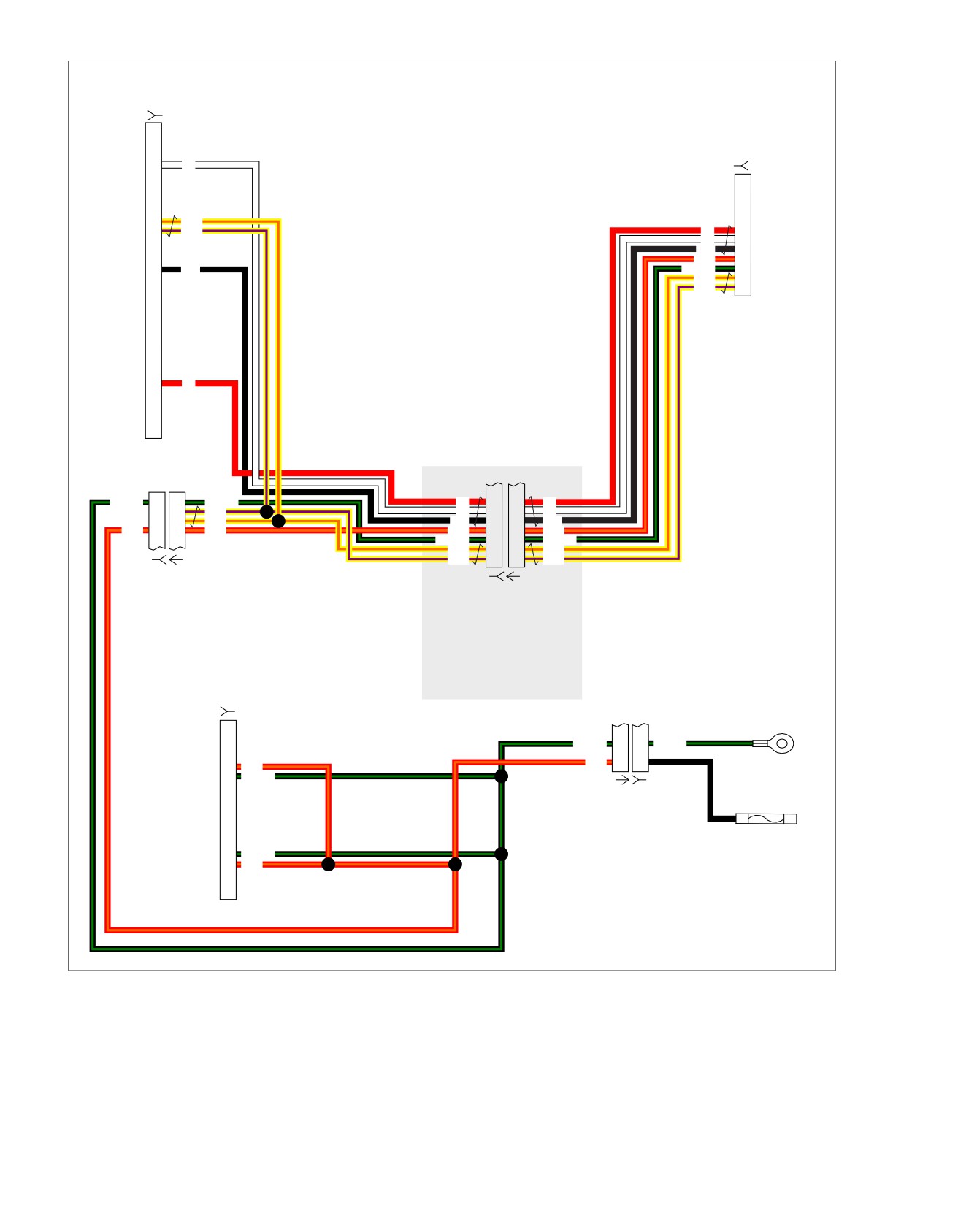
HOME
em00202
(BK)
[28B]
XM
[185B]
7
W
13
Y/O
To
14
Y/V
R
6
W
7
XM module
To
BK
8
[185A]
ultra
R/O
9
18
BK
BK/GN
10
radio
Y/O
11
[28A]
Y/V
12
30
R
Interconnect
BK/GN
6
6
BK/GN
R
6
6
R
5
Y/V
W
7
7
W
4
Y/O
BK
8
8
BK
R/O
3
3
R/O
R/O
9
9
R/O
BK/GN
10
10
BK/GN
Y/O
11
11
Y/O
Audio
Y/V
12
12
Y/V
[6B] [6A]
Harness
(BK)
C.B. [184B]
[184C]
P/N 70169-06 - P&A non-ultra
harness replaces P/N's
70160-06 & 70164-06 and is
represented when this
connector does not exist.
For all except FLHTCUI
Main
[27B]
Harness
To ground
BK/GN
C
C
BK/GN
R/O
A
A
10
R/O
11
BK/GN
To
[15A] [15B]
radio
(BK)
[27A]
(BK)
To radio memory
19
BK/GN
fuse 15 amp
20
R/O
Figure 5-40. XM Circuit
5-124 2008 Touring Diagnostics: Audio System

HOME
Table 5-41. FLHT/C/U Wire Harness Connectors
NO.
DESCRIPTION
TYPE
LOCATION
[6]
Audio to interconnect har-
6-Place Deutsch (Black)
Inner fairing - left side of radio
ness
[15]
Main
to interconnect harness
4-Place Packard
Inner fairing - right fairing bracket
[27]
Radio
23-Place Amp
Inner fairing - back of radio (right side)
[28]
Radio
35-Place Amp
Inner fairing - back of radio (left side)
[184]
CB Module
12-Place Mini-Deutsch
Inner fairing - left side of radio
[185]
XM Module
12-Place Mini-Deutsch
Inner fairing - top of radio (left side)
2008 Touring Diagnostics: Audio System 5-125
HOME
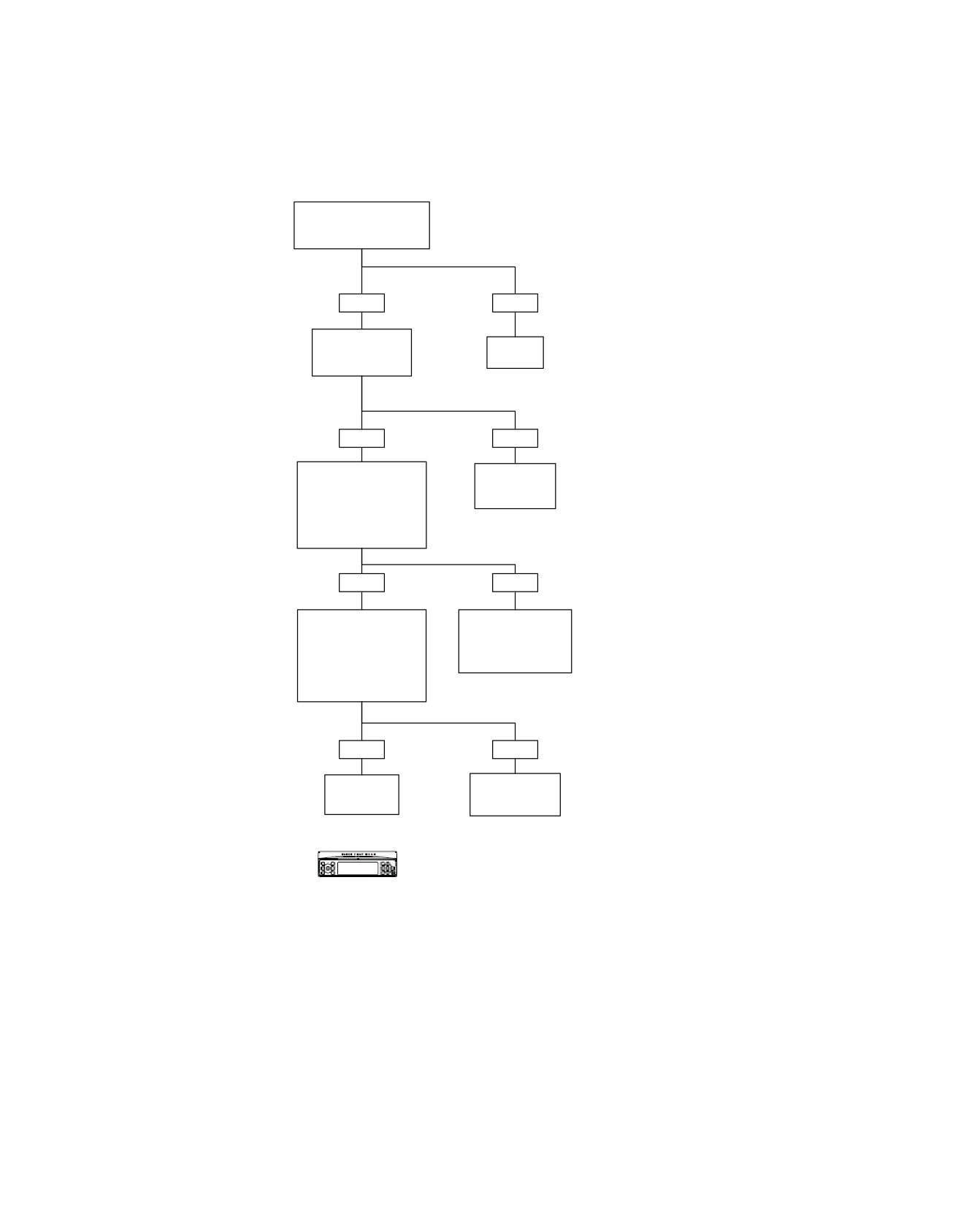
XM - No or Intermittent Reception: Symptom 16
Antenna Located in
“Open Area” with Line of
Site to Southern Sky?
YES
NO
Are Metal Objects
Relocate
Obstructing Properly
Vehicle.
Installed Antenna?
YES
NO
With Ignition ON, Measure
Relocate Vehicle
Voltage at XM Antenna
and/or Properly
Connector at Back of XM
Install Antenna.
Module Between Center
Contact and Radio Case.
Does Voltage Equal
4.25-4.75V?
YES
NO
With Ignition OFF, Measure
Locate and Repair
Resistance of XM
Short to Voltage on (R),
Antenna at XM Antenna
(W) or (BK) Wires
Connector Between Center
Between Connectors
Contact and Cable Shield.
[185B] and [28B].
Does Resistance Equal 35-
6126
55 Ohms?
YES
NO
Replace
Replace
XM Module.
XM Antenna.
6126
6146
Confirm proper operation with no DTCs.
fc00560_en
5-126 2008 Touring Diagnostics: Audio System
HOME
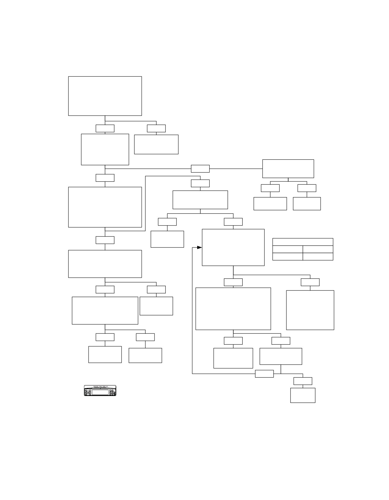
Navigation Inoperative: Symptom 17 (Part 1 of 2)
Verify Navigation CD is in Good
Condition and Navigation Module
is Properly Seated Onto
Radio and Screws are Installed.
Is Navigation CD in Good Condition
and Module Properly
Seated and Installed?
YES
NO
Press NAV Button on
Remove and
Radio With Power ON.
Reinstall Module
Does the Radio Show
and Try Again.
Navigation Screen (i.e.
Not the “Navigation is
Not Installed” Screen)?
Swap With Known
NO
Good Navigation Module.
Does It Work?
YES
NO
YES
NO
Disconnect Radio Power for 15
Does the Starting Navigation
Seconds. Reconnect Power.
Screen Show
System
Replace
Turn the Radio ON With No Navigation
“GPS Module Error?”
OK.
Radio.
CD Inserted and Press NAV Button.
Does Display Show “GPS Antenna
8197
6101
Error” in the Starting Navigation
Screen (at the Bottom)?
YES
NO
Go to FM Radio Band. Enter
Replace
Radio Test Menu (Softkey 1,
YES
Navigation
Softkey 3 and OK
DIAGNOSTIC SPEED TYPE
Module.
Simultaneously).
Speed Type
Model Year
6182
Use Arrow Down to Select
Measure Voltage at Navigation
Diagnostic Speed Type.
J1850
2006-2008
Antenna Connector at Back of
Is Speed Type Correct?
Navigation Module Between Center
Contact and Radio Case. Does
Voltage Equal 4.5-5.3V?
YES
NO
YES
NO
Press Arrow Down Until Diagnostic
Speed Input Appears. If
Press “Change” at
Measure Resistance at Navigation
Replace
Stationary, Should Read 0. Ride
Softkey 4 Until Correct
Antenna Connector Between
Navigation
Motorcycle Around Block With
Speed Type is
Center Contact and Cable Shield.
Module.
This Screen Showing (Monitor
Displayed. Press “Exit”
Does Resistance Equal 105K to
Both This Display and Speedometer).
at Softkey 6 to Store
122K Ohm?
6182
Does the Number on
Setting. Cycle Ignition
the Screen Increment?
Switch.
YES
NO
YES
NO
Replace
Replace
Go to NAVIGATION
Did Speedometer
Navigation
Navigation
INOPERATIVE:
Show Correct
Module.
Antenna.
Symptom 17
Speed?
6182
6183
(Part 2 of 2).
YES
NO
Confirm proper operation with no DTCs.
Fix Speed
Input.
fc00561_en
2008 Touring Diagnostics: Audio System 5-127
HOME
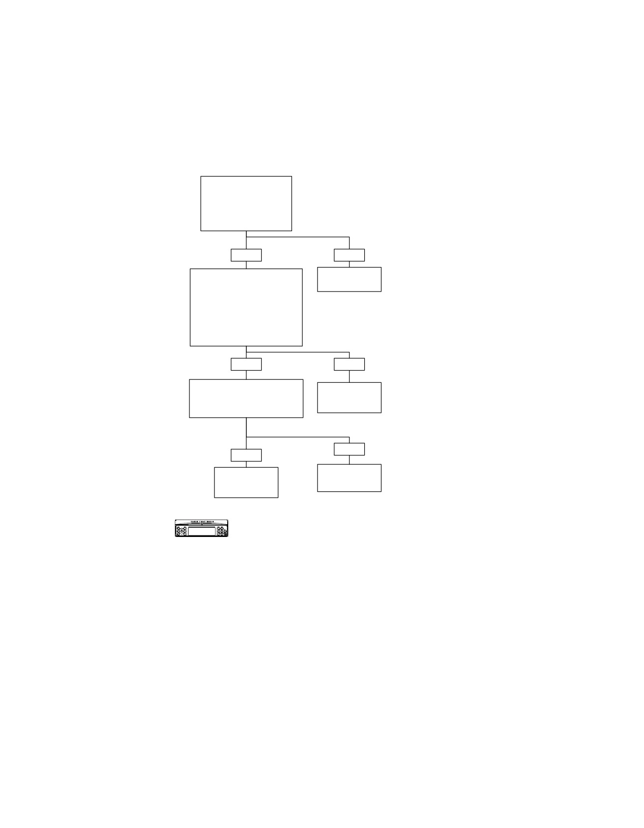
Navigation Inoperative: Symptom 17 (Part 2 of 2)
From NAVIGATION
INOPERATIVE: Symptom
17
(Part 1 of 2).
Antenna Located in
“Open Area” With Line of
Site to Southern Sky?
YES
NO
Insert Navigation CD and Let it
Relocate
Load. Press OK When Prompted
Motorcycle.
and Go to Save (Softkey 5).
Press Softkey 4 (GPS). Observe
Number of Satellites and Latitude/
Longitude.
Are There Any Satellites (May Have
to Wait Up to 5 or 10 Minutes).
Do You Have Any Satellites?
YES
NO
Insure That Navigation Antenna
Replace
is Properly Installed With No
Navigation
Obstructions (Stock Configuration).
Module.
Is Antenna Properly Installed?
6182
NO
YES
Replace
Properly Install
Navigation
Antenna.
Module.
6182
Confirm proper operation with no DTCs.
fc00562_en
5-128 2008 Touring Diagnostics: Audio System
HOME
AVC Inoperative: Symptom 18
Go to FM Radio Band. Enter Radio
DIAGNOSTIC SPEED TYPE
Test Menu (Softkey 1, Softkey 3 and
Speed Type
Model Year
OK Simultaneously). Use Arrow
Down to Select Diagnostic Speed Type.
J1850
2006-2008
Is Speed Type Correct?
YES
NO
Press Arrow Down Until Diagnostic
Press “Change” at
Speed Input Appears. If
Softkey 4 Until Correct
Stationary, Should Read 0. Ride
Speed Type is
Motorcycle Around Block With
Displayed. Press “Exit”
This Screen Showing (Monitor
at Softkey 6 to Store
Both This Display and Speedometer).
Setting. Cycle Ignition
Does the Number on the Screen
Switch.
Increment?
YES
NO
Adjust AVC by Pressing
See DTC U1016,
“Audio +” Until One or
J1850 LOST
More Bars are Present.
COMMUNICATIONS
WITH ECM.
Confirm proper operation with no DTCs.
fc00563_en
2008 Touring Diagnostics: Audio System 5-129
HOME
Handlebar, Passenger or Sidecar Switches Inoperative: Symptom 19 (Part 1 of 4)
While Pressing Any Two Softkeys (Presets), Turn
Ignition Switch ON to Enter Diagnostic Mode.
Will Radio Enter Diagnostic Mode?
YES
NO
Replace
Is DTC Present?
Radio.
6101
YES
NO
See DIAGNOSIS for applicable DTC:
DTC
DESCRIPTION
GO TO
B2006
Radio Switches Stuck or Open
Replace Radio.
B2007
Handlebar Switches Shorted High
Audio
Handlebar Audio Switch Shorted High: DTC B2007 (Part 1 of 3)
Mode
Handlebar Mode Switch Shorted High: DTC B2007 (Part 2 of 3)
Depress applicable switch to verify
Handlebar PPT/Squelch Switch Shorted High:
PTT/Squelch
handlebar, passenger and
DTC B2007 (Part 3 of 3)
sidecar switch functionality:
B2008
Handlebar Switches Shorted Low
Audio Up
Audio
Handlebar Audio Switch Shorted Low: DTC B2008 (Part 1 of 3)
Audio DN
Mode
Handlebar Mode Switch Shorted Low: DTC B2008 (Part 2 of 3)
Audio
Handlebar PPT/Squelch Switch Shorted Low:
PTT/Squelch
Mode Up
DTC B2008 (Part 3 of 3)
Mode DN
B2009
Handlebar Switches Stuck or Open
Mode
Audio
Handlebar Audio Switch Stuck or Open: DTC B2009 (Part 1 of 3)
PTT
Mode
Handlebar Mode Switch Stuck or Open: DTC B2009 (Part 2 of 3)
Squelch +
Handlebar PPT/Squelch Switch Stuck or Open:
PTT/Squelch
Squelch -
DTC B2009 (Part 3 of 3)
The Display Will Show Each
B2010
Passenger Switches Shorted High
Function When Pressed.
Passenger Audio/PPT Switch Shorted High:
Audio/PTT
Does it?
DTC B2010 (Part 1 of 2)
Mode
Passenger Mode Switch Shorted High: DTC B2010 (Part 2 of 2)
B2011
Passenger Switches Shorted Low
YES
NO
Passenger Audio/PTT Switch Shorted Low:
Audio/PTT
DTC B2011 (Part 1 of 2)
No Current Fault Found.
Mode
Passenger Mode Switch Shorted Low: DTC B2011 (Part 2 of 2)
Which Switches Are
Repeat Function Verification
B2012
Passenger Switches Stuck or Open
Inoperative?
While Wiggling Harness.
Passenger Audio/PTT Switch Stuck or Open:
Audio/PTT
DTC B2012 (Part 1 of 2)
Mode
Passenger Mode Switch Stuck or Open: DTC B2012 (Part 2 of 2)
If equipped with a sidecar, disconnect connector [197B]
B2013
Sidecar Switches Shorted High
and perform Functionality Test. If problem is no longer
PTT/Mode
Sidecar PPT/Mode Switches Shorted High: DTC B2013
present proceed to “Sidecar Switch”.
If problem is still present disconnect connector [28B]
B2014
Sidecar Switches Shorted Low
from rear of Radio and perform Functionality Test again.
PTT/Mode
Sidecar PPT/Mode Switches Shorted Low: DTC B2014
If problem does not appear proceed to “Passenger
Switches”. If problem is still present proceed to
B2015
Sidecar Switches Stuck or Open
“Handlebar Switches”.
PTT/Mode
Sidecar PPT/Mode Switches Stuck or Open: DTC B2015
Handlebar
Passenger
Sidecar
Switches
Switches
Switches
Go to HANDLEBAR
Go to PASSENGER
Go to SIDECAR SWITCHES
SWITCHES INOPERATIVE:
SWITCHES INOPERATIVE:
INOPERATIVE: Symptom 19
Symptom 19 (Part 3 of 4).
Symptom 19 (Part 2 of 4).
(Part 4 of 4).
Confirm proper operation with no DTCs.
fc00564_en
5-130 2008 Touring Diagnostics: Audio System