Harley Davidson 2008 Touring Models. Electrical Diagnostics Manual - page 4
HOME
BREAKOUT BOX:
SPEEDOMETER/TACHOMETER
2.5
GENERAL
ed02037
PART NUMBER
TOOL NAME
HD-42682
BREAKOUT BOX
HD-46601
INSTRUMENT HARNESS ADAPTERS
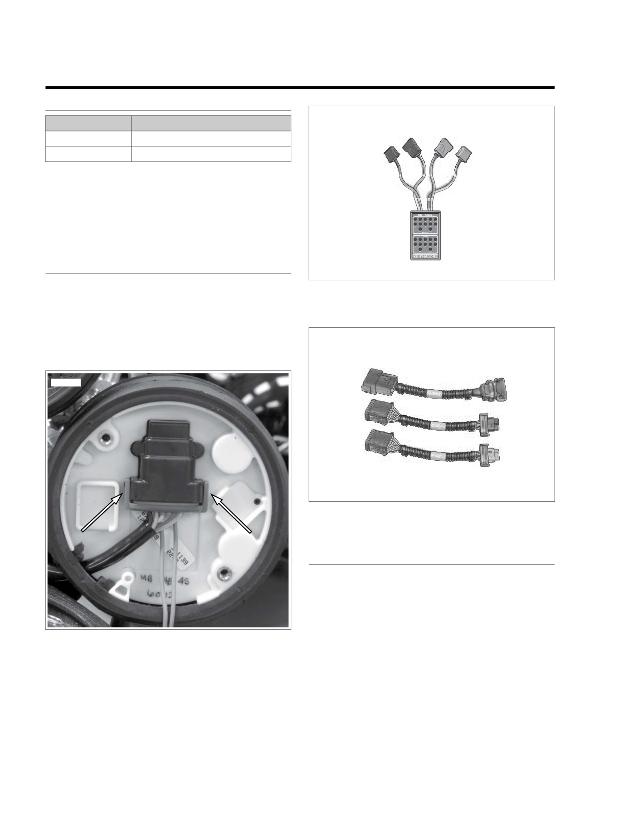
The BREAKOUT BOX (Part No. HD-42682) and INSTRUMENT
HARNESS ADAPTERS (Part No. HD-46601) connect to
speedometer connector [39]. Used in conjunction with a DVOM,
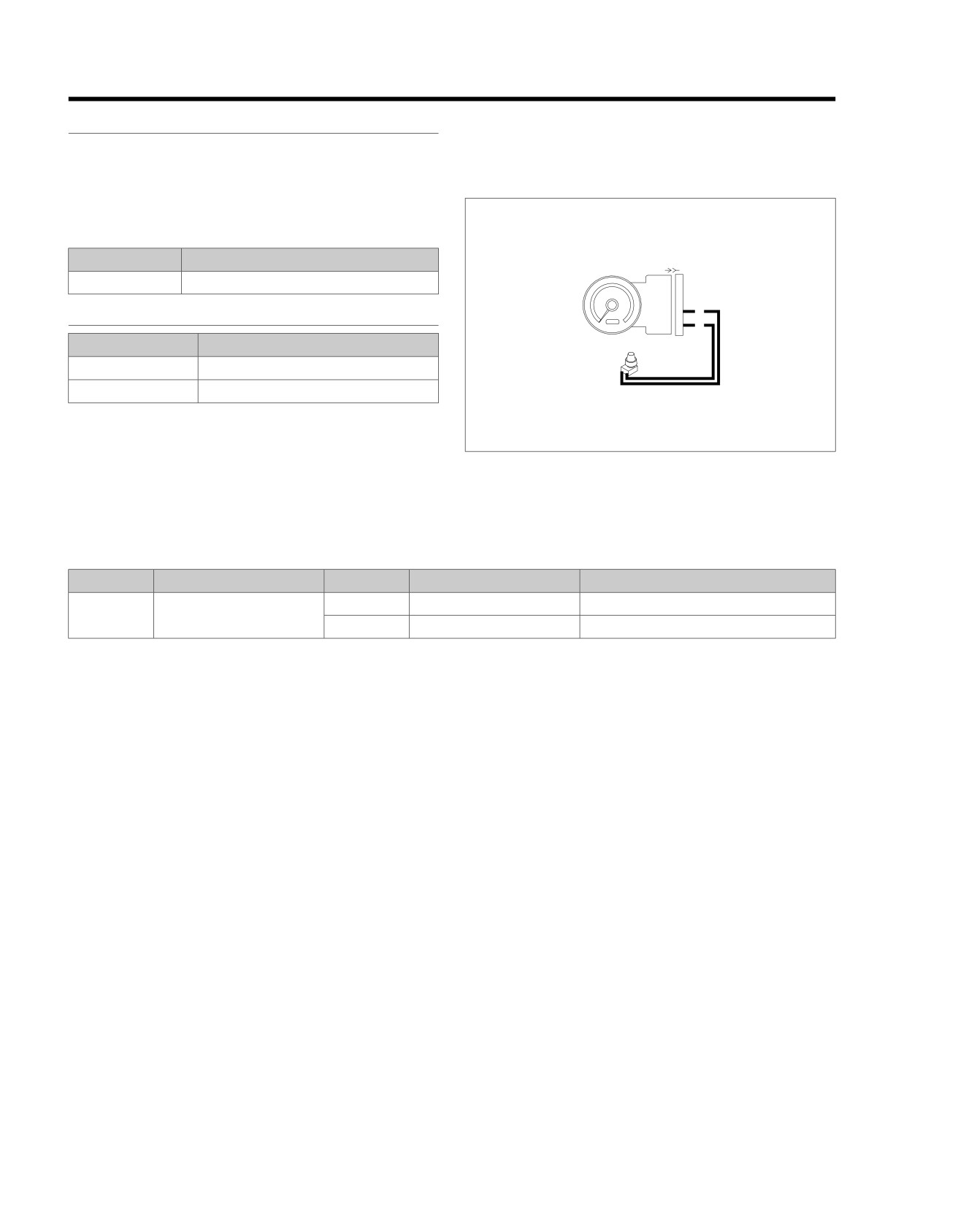
it allows circuit diagnosis of wiring harness and connections
without having to probe with sharp objects.
NOTE
See wiring diagrams for speedometer terminal functions.
INSTALLATION
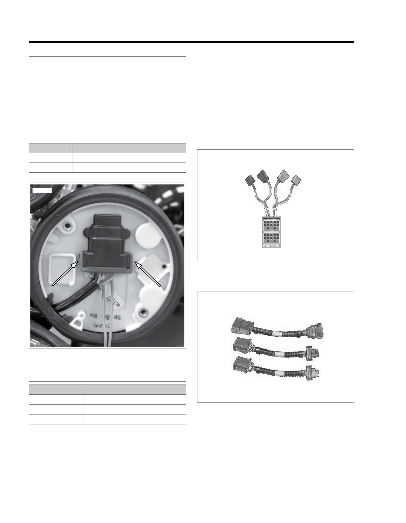
1. See Figure 2-6. Release the external latches and remove
Figure 2-7. Breakout Box (Part No. HD-42682)
connector [39B].
2. See Figure 2-8. Connect instrument harness adapters to
connectors [39A] and [39B].
3. See Figure 2-7. Attach connectors from Breakout Box to
ed02039
instrument harness adapters.
ed02036
Figure 2-8. Instrument Harness Adapters (Part No.
HD-46601)
REMOVAL
1. Detach connectors from Breakout Box to instrument har-
ness adapters.
2. Detach instrument harness adapters from connectors [39A]
and [39B].
3. Install connector [39B] to speedometer.
Figure 2-6. Speedometer Connector [39]
2-16 2008 Touring Diagnostics: Instruments
HOME
FUEL GAUGE
2.6
1.
Remove gauge. Ground (Y/W) wire of fuel gauge sender
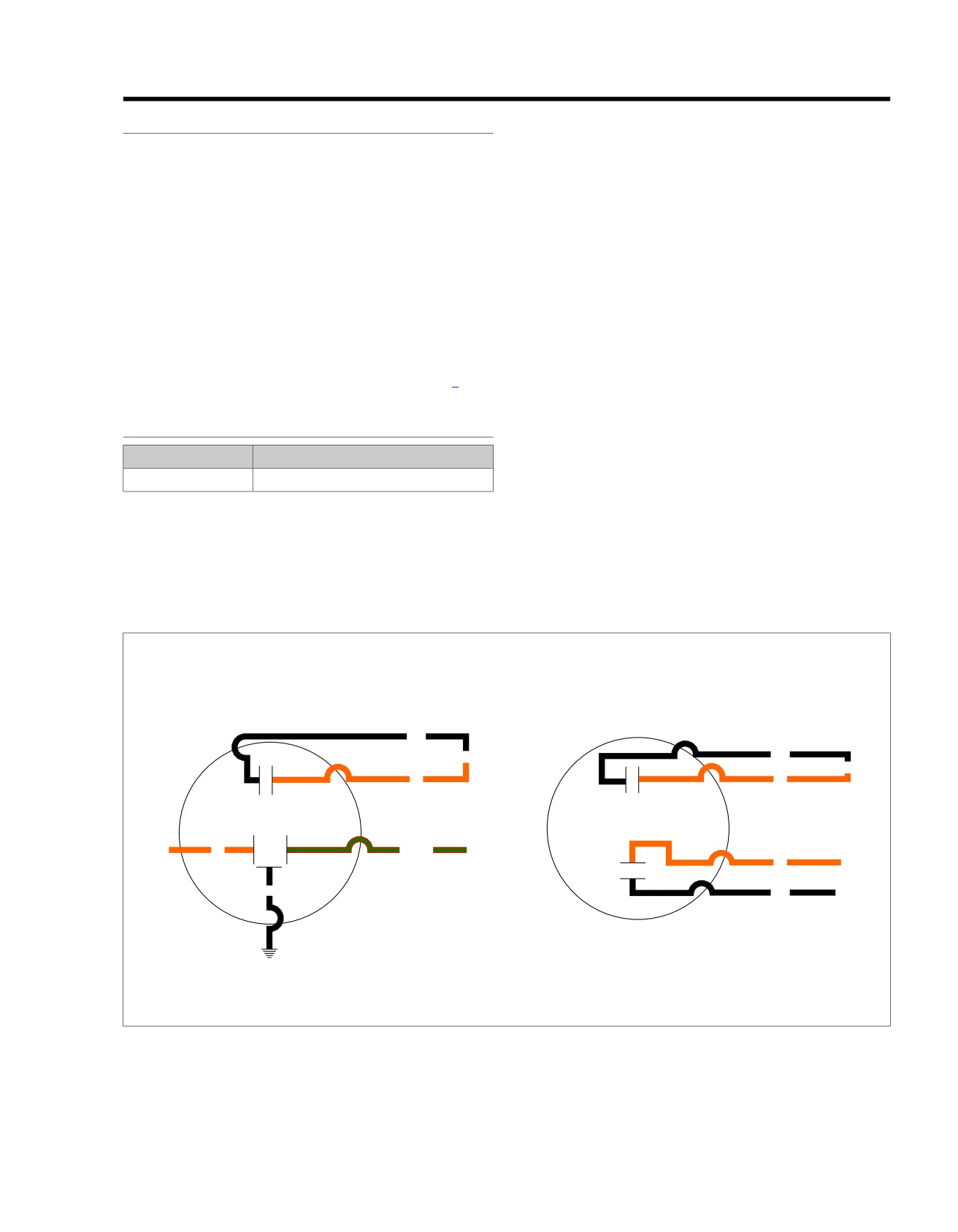
THEORY OF OPERATION
located at bottom of gauge. Turn ignition switch to IGNI-
With ignition switch turned to IGNITION, the fuel gauge is
TION.
connected to +12 volts. Current flows through the gauge and
a. Fuel gauge must indicate FULL. If gauge indicated
variable resistor in the fuel gauge sending unit to ground. The
FULL, gauge is functioning correctly. Proceed to step
sending unit float controls the amount of resistance in the
2.
variable resistor.
b. If gauge did not indicate FULL, proceed to step 3.
Inoperative gauges may be caused by several circumstances.
•
Sender or fuel gauge not grounded.
2.
Set MULTI-METER (Part No. HD-35500) to RXI scale to
measure the resistance of the sending unit. Place one
•
Malfunction in sender or fuel gauge.
probe on (Y/W) and the other probe on chassis ground.
•
Broken or disconnected wire from ignition switch to fuel
If fuel tank is full, the reading should be 30-50 ohms. An
gauge.
empty tank should have a 240-260 ohm resistance. A half
full tank will be approximately 125-165 ohms.
•
Corroded connections at fuel gauge.
If a very high resistance or infinity is indicated on the
Use the 2.6 FUEL GAUGE, Fuel Gauge and Sender Test to
meter, the sender may be "open" or not grounded. Check
test suspect components.
that sender and fuel tank are grounded by placing one
FUEL GAUGE AND SENDER TEST
probe of Multi-Meter on sender flange and the other probe
on crankcase. Meter must indicate one ohm or less.
PART NUMBER
TOOL NAME
Replace sender if one ohm or less was present. If a higher
resistance is present, check for poor connection on ground
HD-35500
MULTI-METER
wire.
NOTE
3.
Check voltage to (O/W) (+) and (BK) (-) wire of fuel gauge
Always refer to the applicable wiring diagram when
connector [117] if gauge did not indicate FULL.
troubleshooting instruments or gauges.
a. Correct reading is equivalent to battery voltage.
b. If battery voltage is not present check for broken or
disconnected wire. Replace gauge if wiring problem
is not found.
em01174
BK
Light
BK
Light
O
O
Oil
Pressure
Voltmeter
O
BN/GN
To Sender
+
O
To +12V
BK
GND
BK
NOTE
Color Code:
All gauges are shown
BK-Black
as viewed from rear.
BN/GN-Brown/Green
O-Orange
Figure 2-9. Connections for Gauges
2008 Touring Diagnostics: Instruments 2-17
HOME
OIL,
AIR AND VOLTMETER GAUGES
2.7
4. If the low oil pressure light functions correctly, but the
OIL PRESSURE GAUGE AND INDICATOR
pressure gauge does not, Then proceed as follows:
LIGHT
a. Remove electrical connector from oil pressure sending
PART NUMBER
TOOL NAME
unit. Turn the ignition switch to IGNITION. The gauge
must read zero.
HD-41404-B
HARNESS CONNECTOR TEST KIT
b. Ground (BN/GN) wire terminal to crankcase. The
Problem
gauge must read full scale 60 PSI.
Low oil pressure light remains on with engine running above
c. Replace the sending unit if the above gauge readings
idle and/or oil pressure gauge does not work.
are obtained. If the gauge readings are not obtained,
then replace the pressure gauge.
Cause 3
Do not operate the engine when the oil level is below the
add mark on the dipstick at operating temperature. Engine
No power to gauge.
damage will result. (00187b)
Solution 3
Cause 1
See Voltmeter Gauge.
No oil pressure due to lack of oil or faulty oil pump.
AMBIENT AIR TEMPERATURE GAUGE
Solution 1
Problem
1. Check oil level. Add oil if low.
Gauge inoperative.
2. Restart engine and verify that oil pressure light goes off
and gauge indicates pressure. If problem still exists, refer
Cause 1
to OIL PUMP in the Service Manual.
Sensor not grounded or open between sensor and gauge.
Cause 2
Solution 1
Contacts in pressure sending unit not opening to shut off light.
Test for continuity between terminal "1" and ground and ter-
Variable resistor in sender is shorted to ground.
minal "3" and gauge. Repair if open.
Solution 2
Cause 2
1.
Locate the oil pressure sending unit on the front right side
Broken or disconnected power or ground wire to gauge.
of the crankcase.
Solution 2
2.
Verify that the electrical connector is properly connected
Check for 12V between terminals "1" and "3" at connector
to the sending unit.
[115A]. Replace gauge if voltage is present. Use voltage drop
3.
If the oil pressure gauge indicates pressure but the low oil
tests and continuity checks to isolate if voltage is not present.
pressure light remains on proceed as follows:
Cause 3
a. Remove electrical connector from oil pressure sending
unit. Using ohmmeter and HARNESS CONNECTOR
Malfunction in gauge or sensor.
TEST KIT (Part No. HD-41404-B) gray socket probe
Solution 3
and patch cord, place one probe on indicator lamp
terminal (closest to latch on sending unit), place the
Measure resistance between terminals "1" and "3" at
65-
other probe on the crankcase. Ohmmeter must read
85°F (18.3-29.4°C). Resistance should be 43-31 ohms. Replace
less than one ohm.
sensor if out of range, replace gauge if within range.
b. Start the engine and run at a fast idle. The ohmmeter
VOLTMETER GAUGE
must read infinity.
Problem
c. Replace the sending unit if the above meter readings
are not obtained.
Meter inoperative.
Cause
Broken or disconnected leads to meter or open meter winding.
Solution
1. With ignition switch turned to IGNITION, verify that 12V
is present at "±" terminal on voltmeter. With ignition switch
turned to OFF, check ground terminal for continuity to
ground.
2-18 2008 Touring Diagnostics: Instruments
HOME
2. Replace the voltmeter if 12V is present and ground ter-
3. If 12V is not present, trace wiring until disconnected or
minal is grounded.
broken wire is found and repair as necessary. If ground
terminal is not grounded, refer to wiring diagram and
repeat procedure given for 12V lead.
2008 Touring Diagnostics: Instruments 2-19
HOME
INDICATOR LIGHTS: ALL
2.8
serviceable. If one LED is bad, the entire assembly must be
GENERAL
replaced.
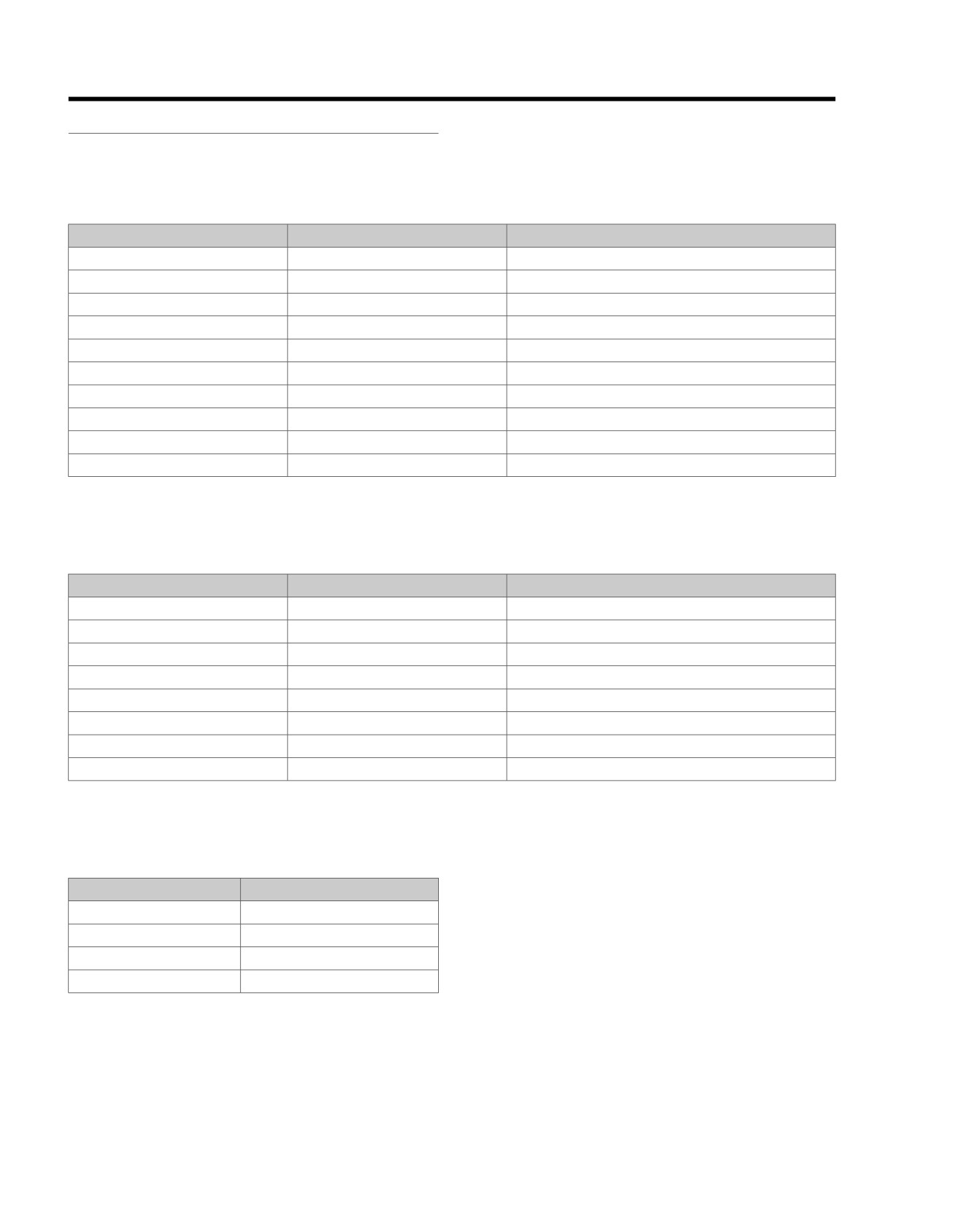
See Figure 2-10. All models are equipped with Light Emitting
See
2.8 INDICATOR LIGHTS: ALL, Diagnostics for
Diode (LED) indicators. The indicator lights assembly is not
troubleshooting procedures.
Table 2-5. Indicator Lamp Connector [21] (All But FLHR/C/S)
TERMINAL
WIRE COLOR
FUNCTION
1
Brown
Right Turn Power
2
Green/Y
ellow
Oil Pressure Lamp To Switch
3
White
High Beam Power
4
Violet
Left Turn Power
5
Black
Ground
6
Orange
Neutral/Oil Pressure Power
7
T
an
Neutral Lamp To Switch
8
Not Used
N/A
9
Not Used
N/A
10
Not Used
N/A
Table 2-6. Indicator Lamp Connector [21] (FLHR/C/S)
TERMINAL
WIRE COLOR
FUNCTION
1
Violet
Left Turn Power
2
White
High Beam Power
3
Green/Y
ellow
Oil Pressure Lamp To Switch
4
Brown
Right Turn Power
5
T
an
Neutral Lamp To Switch
6
Orange
Neutral/Oil Pressure Power
7
Black
Ground
8
Not Used
N/A
Table 2-7. Indicator Lamp Wiring
INDICATOR LAMP
CONNECTION
Oil pressure
Ground through switch
Neutral
Ground through harness
High beam
12V when active
Right/left turn
12V when active
2-20 2008 Touring Diagnostics: Instruments
HOME
ed02040
ed02041
1
2
6
5
4
3
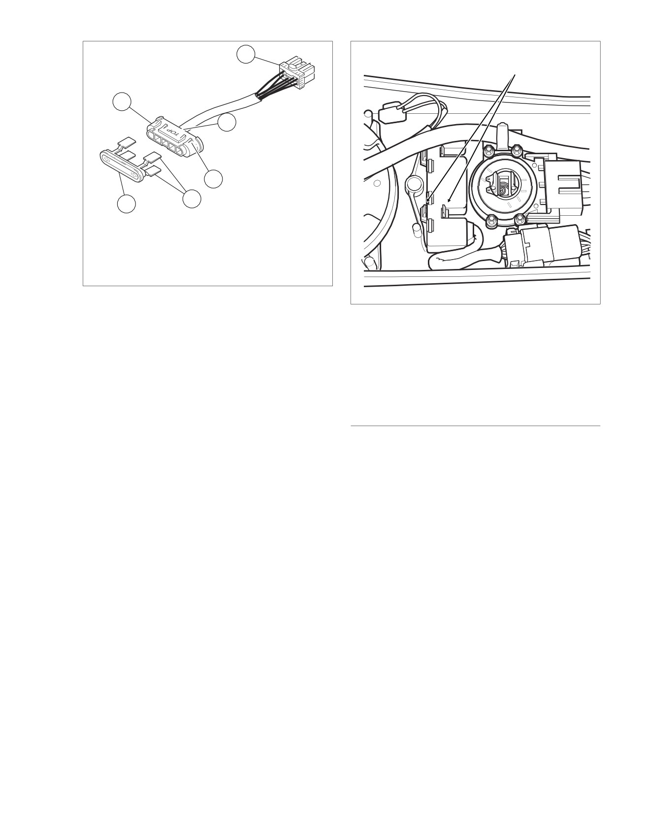
1. Indicator Lights Connector
2. Indicator Lights Assembly
3. Lens
4. Paddles
5. Index Tabs
6. Orientation Stamp
Figure 2-10. Indicator Lights Assembly (FLHS, FLHT/C/U,
FLTR)
Figure 2-11. Release Paddles to Free Indicator Light
Assembly (FLHR/C)
Job/Time Code Values
Dealership technicians filing warranty claims should use the
job/time code values printed in bold text underneath the
appropriate repair.
DIAGNOSTICS
2008 Touring Diagnostics: Instruments 2-21
HOME
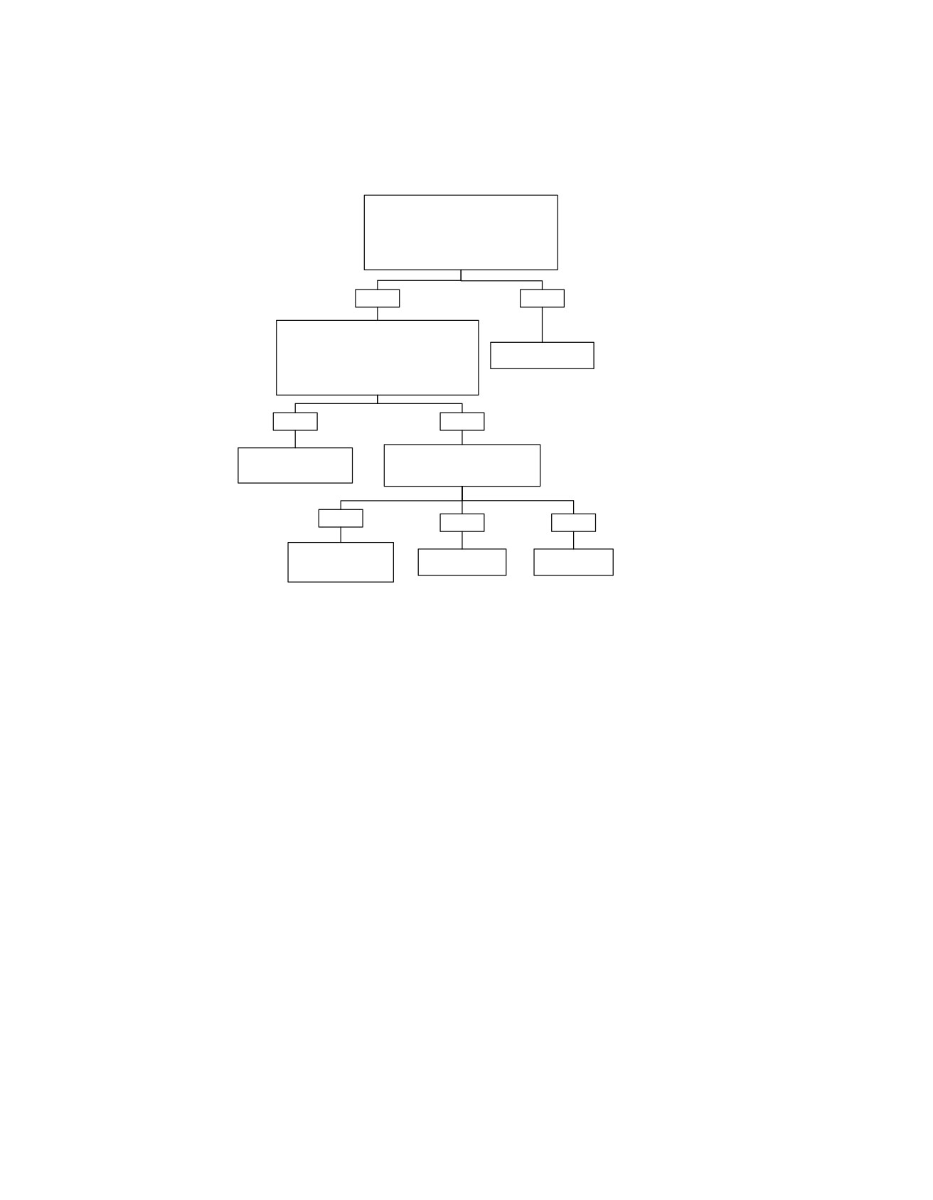
Oil Pressure or Neutral Indicator Will Not Function
Turn the Ignition Switch to IGNITION.
Check for battery voltage at connector
[21A], terminal “6”.
Turn OFF Ignition Switch.
Was battery voltage present?
YES
NO
With transmission in neutral, check
for continuity to Ground at connector
[21A], terminal “7” (terminal “5” on FLHR
Check for bad fuses
models) and/or terminal “2” (terminal “3” on
or locate open.
FLHR models).
5048
Is continuity present?
YES
NO
Check for continuity through
Replace Indicator Lights
switch.
Assembly.
Is continuity present?
5191
YES
NO
NO
Repair open in (GN/Y)
Replace Oil
Replace Neutral
wire (oil pressure) or
Pressure Switch.
Switch.
(TN) wire (neutral).
5161
5157
5048
fc01090_en
2-22 2008 Touring Diagnostics: Instruments
HOME
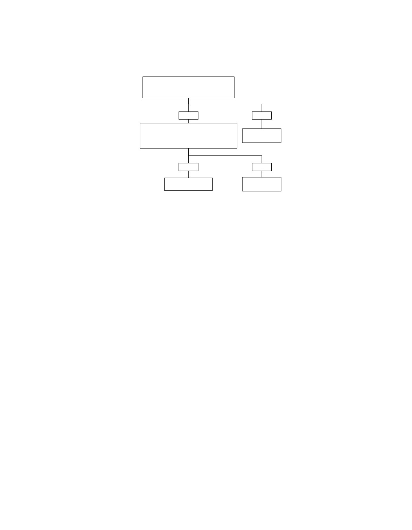
High Beam or R/L Turn Signal Indicator Will Not Function
Check for Ground at connector [21A],
terminal “1”, terminal “3” (terminal “2” on FLHR
models) and/or terminal “4”.
Is continuity to Ground present?
YES
NO
Check for 12V when circuit is active:
connector [21A], terminal “4”, terminal “1” or
Locate and repair
terminal “3” (terminal “2” on FLHR models).
open in circuit.
Is voltage present?
5048
YES
NO
Replace Indicator
Locate and repair
Lights Assembly.
open in circuit.
5191
5048
fc01091_en
2008 Touring Diagnostics: Instruments 2-23
HOME
DTC B1004,
B1005
2.9
GENERAL
Diagnostic Notes
See Figure 2-12. The fuel level is monitored by the speedo-
Each reference number below correlates to a circled number
meter terminal "9" of connector [39] (Y/W).
on the flow chart(s).
•
If the voltage on terminal "9" of connector [39] exceeds
1. See Figure 2-14. Use HARNESS CONNECTOR TEST
the lower limit for greater than or equal to 15 seconds a
KIT (Part No. HD-41404-B), brown pin probe and patch
DTC B1004 will set.
cord.
•
If the voltage on terminal "9" of connector [39] exceeds
2. See Figure 2-13. Connect BREAKOUT BOX (Part No. HD-
the upper limit (or is open) for greater than or equal to 15
42682) and INSTRUMENT HARNESS ADAPTERS (Part
seconds a DTC B1005 will set.
No. HD-46601) between wire harness and speedometer.
3. Use HARNESS CONNECTOR TEST KIT (Part No. HD-
Table 2-8. Code Description
41404-B), gray pin probe and patch cord.
DTC
DESCRIPTION
B1004
Fuel level sending unit low
ed02037
B1005
Fuel level sending unit high/open
ed02036
Figure 2-13. Breakout Box (Part No. HD-42682)
ed02039
Figure 2-12. Speedometer Connector [39]
DIAGNOSTICS
PART NUMBER
TOOL NAME
HD-41404-B
HARNESS CONNECTOR TEST KIT
HD-42682
BREAKOUT BOX
Figure 2-14. Instrument Harness Adapters (Part No.
HD-46601)
HD-46601
INSTRUMENT HARNESS ADAPTERS
Diagnostic Tips
If fuel gauge is performing erratically (possible false DTCs),
inspect for unobstructed movement of sending unit arm. Repair
or align as necessary.
2-24 2008 Touring Diagnostics: Instruments
HOME
em01047
Fuel Gauge
All Except
FLHR/C/S
Fuel Gauge
FLHR/C/S
[117B]
1
3
To accessory fuse
2
[117B]
1
2
4
To battery fuse
A B
C
D
[141A]
Fuel Level
A B
C
D
[141B]
Sender
To instrument fuse
2
3
[13B]
2
3
[13A]
Y/W
5
5
Y/W
BK/GN
12
12
BK/GN
[39B]
1
2
5
6
7
9
12
[39A]
1
2
5 6
7
9
12
[2A] [2B]
FLHX, FLHT/C/U, FLTR
1
2
3
4
8 14 15
[20A]
1
BK/GN
2
FLHR Only
Data Link
LGN/V
3
Connector
GY
4
[91A]
To ignition
fuse
[78B]
69
Speedometer
[78A]
69
ECM
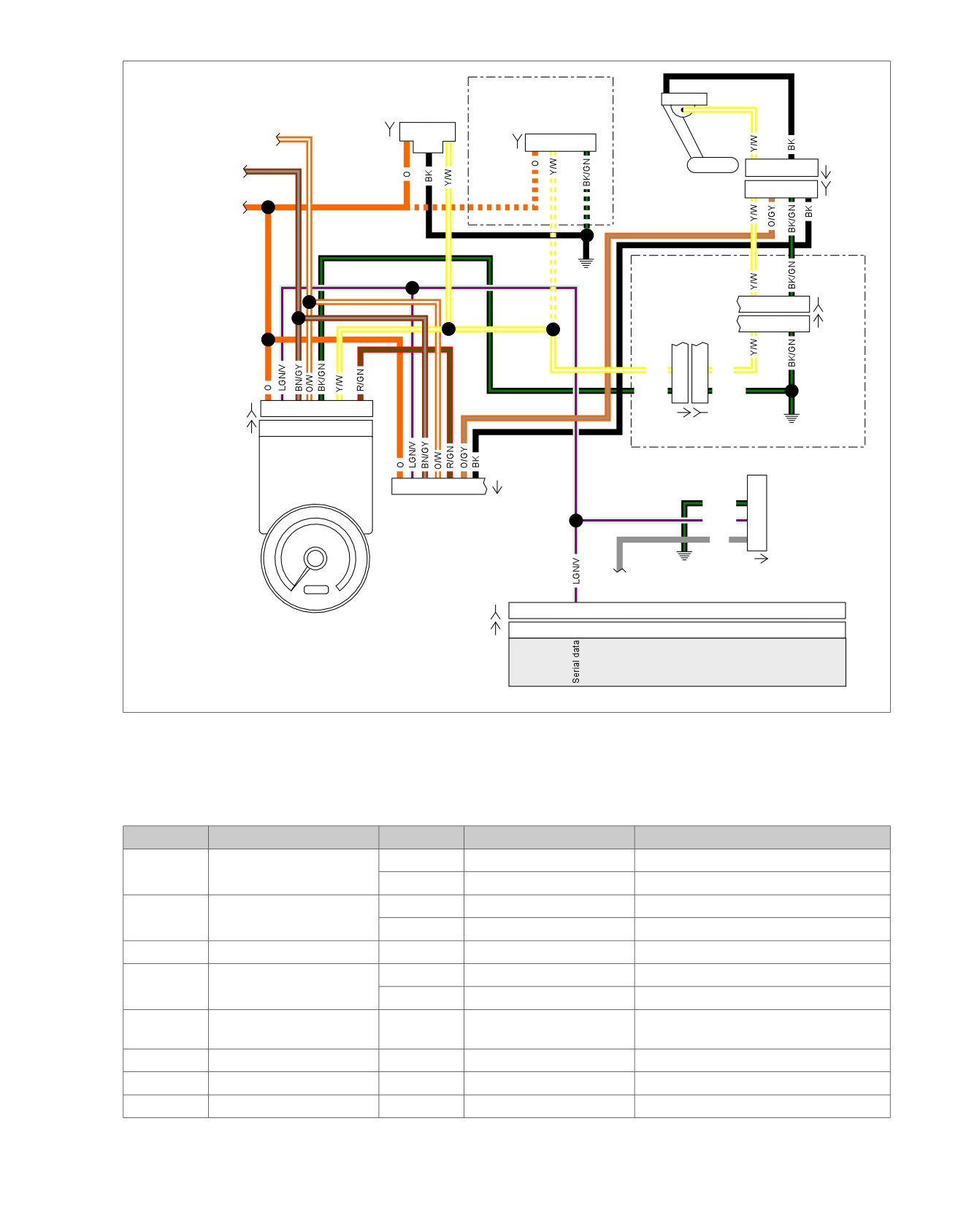
Figure 2-15. Fuel Sender Circuit
Table 2-9. Wire Harness Connectors
NO.
DESCRIPTION
MODEL
TYPE
LOCATION
[2]
Main to interconnect har-
FLHT/C
12-place Molex (Gray)
Inner fairing - left fairing support bracket
ness
FLTR
12-place Molex (Gray)
Inner fairing - below radio (right side)
[13]
Fuel tank harness
FLHT/C
4-place Multilock
Behind fuel tank (under seat)
FLTR
4-place Multilock
Behind fuel tank (under seat)
[20]
Console harness
FLHR
16-place Molex
Under seat
[39]
Speedometer
FLHT/C
12-place Packard
Inner fairing (back of speedometer)
FLTR
12-place Packard
Under bezel (back of speedometer)
[78]
Electronic Control Module
All
73-place Packard
Under seat
(ECM)
[91]
Data link connector
All
4-place Deutsch
Under left side cover
[117]
Fuel gauge
All
Spade terminals
Inner fairing - back of fuel gauge
[141]
Fuel level sender
All
4-place Packard
Top of canopy (under console)
2008 Touring Diagnostics: Instruments 2-25
HOME
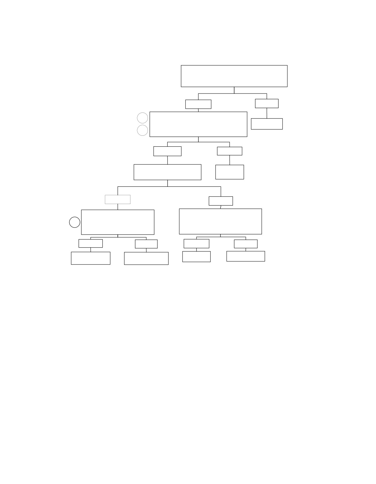
Fuel Level Sending Unit: DTC B1004
Disconnect the fuel gauge connector [117B]. Turn the
Ignition Switch to the IGNITION position. Check for voltage
at terminal “1” of connector [117B].
Is voltage present?
YES
NO
Disconnect the speedometer connector [39B]. Check
2
for continuity between terminal “9” of connector [39B]
and terminal “3” (terminal "2" on FLHR models) of
Repair open.
3
connector [117B].
Is Continuity present?
YES
NO
Check for continuity to Ground in
(Y/W) wire connector [39B].
Repair open.
Is continuity less then 10 ohms?
YES
NO
Disconnect the fuel level sending unit
Connect the fuel gauge connector [117B].
connector [141B]. Check for continuity
Turn the Ignition Switch to the IGNITION
1
between terminal “A” of connector
position. Check for voltage on terminal “9” of
[141B] and ground.
connector [39B].
Is continuity present?
Is voltage present?
YES
NO
YES
NO
Replace
Replace the Fuel
Locate and repair
Replace the Fuel Level
Speedometer.
Gauge.
short to ground.
Sending Unit.
fc01092_en
2-26 2008 Touring Diagnostics: Instruments
HOME
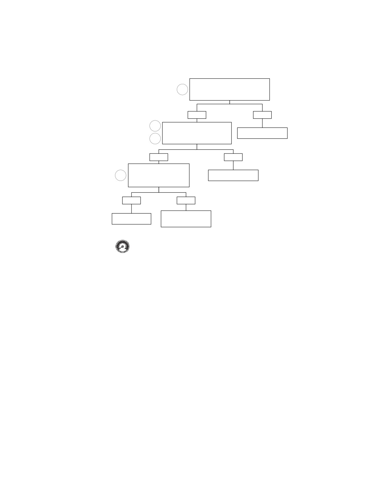
Fuel Level Sending Unit: DTC B1005
Disconnect speedometer connector [39].
Measure voltage on terminal “A” of
1
connector [141B] (Y/W). Should be 0 volts.
Is it?
YES
NO
1
Check continuity between terminal
“A" of connector [141B] (Y/W) and
Locate and repair short
Breakout Box terminal “9”.
to voltage.
2
Continuity present?
YES
NO
Check continuity to ground on
terminal “C” of connector [141B]
Locate and repair open
1
(BK/GN).
on (Y/W) wire.
Is continuity present?
YES
NO
Locate and repair open on
Repair/replace Fuel
(BK/GN) wire (ground
Level Sending Unit.
circuit).
Clear codes using speedometer self diagnostics.
See Section 4.6 SPEEDOMETER SELF DIAGNOSTICS.
Confirm proper operation with no check engine lamp.
fc01093_en
2008 Touring Diagnostics: Instruments 2-27

HOME
DTC B1006,
B1007
2.10
GENERAL
NOTE
Accessory or Ignition Line Overvoltage
ECM or TSM/TSSM/HFSM may also set a battery voltage DTC.
Ignition and accessory voltage is constantly monitored by the
Table 2-10. Code Description
speedometer (terminal "1" ignition and terminal "6" accessory).
If the battery voltage fails to meet normal operating parameters,
DTC
DESCRIPTION
a Diagnostic Trouble Code (DTC) is set.
B1006
Accessory line overvoltage
•
DTC B1006 is displayed when accessory line voltage is
B1007
Ignition line overvoltage
greater than 16.0 volts for longer than 5 seconds.
•
DTC B1007 is displayed when ignition line voltage is
greater than 16.0 volts for longer than 5 seconds.
2-28 2008 Touring Diagnostics: Instruments
HOME
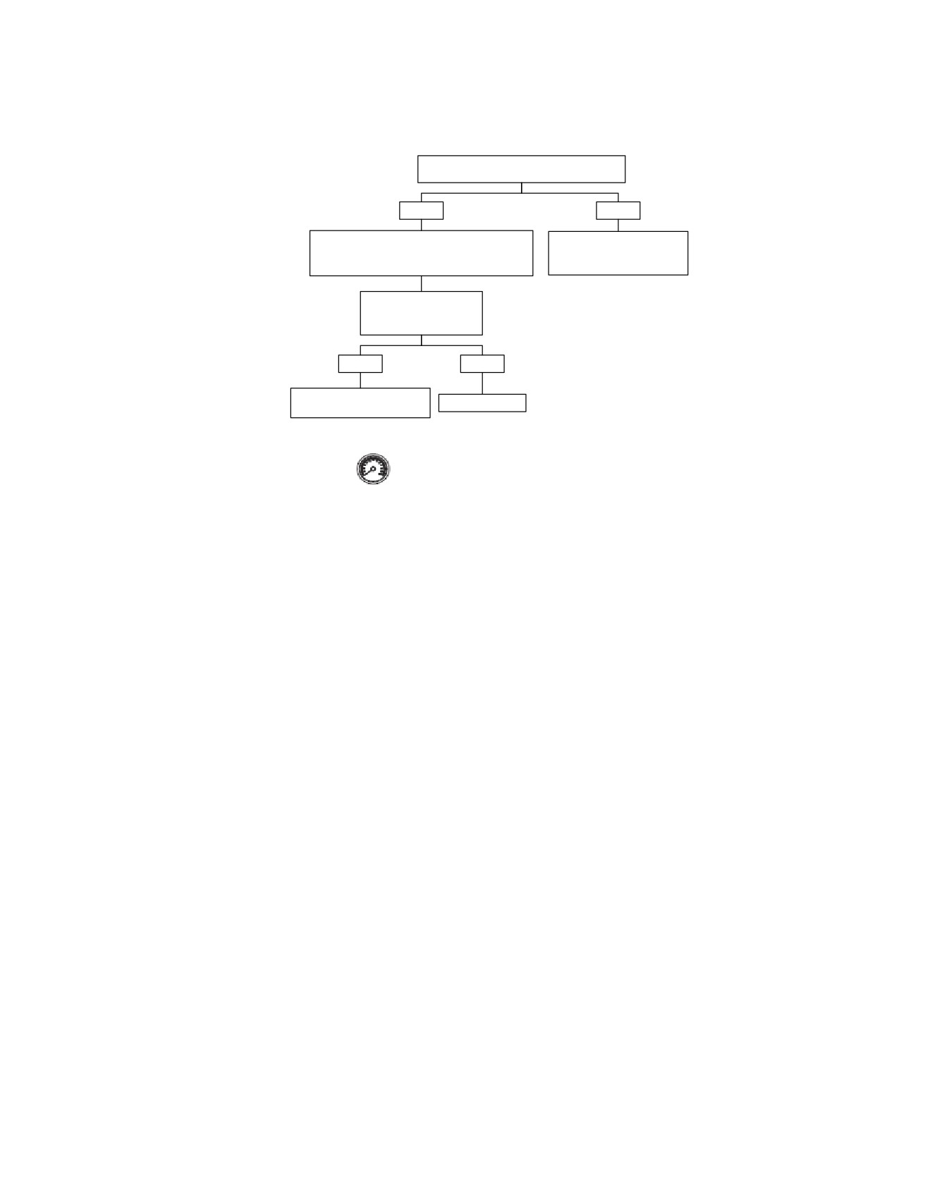
Accessory or Ignition Line Overvoltage: DTC B1006, B1007
Has battery charger been recently connected?
YES
NO
NOTE: Sometimes battery charger may cause
Diagnose charging system.
over voltage condition which will set codes.
See 1.7 CHARGING SYSTEM.
Clear codes.
Start vehicle. Run at 3000
RPM for 5 seconds.
Does code reset?
YES
NO
Diagnose charging system.
System normal.
See 1.7 CHARGING SYSTEM.
Clear codes using speedometer self diagnostics.
See Section 4.6 SPEEDOMETER SELF DIAGNOSTICS.
Confirm proper operation with no Check Engine Lamp.
fc01094_en
2008 Touring Diagnostics: Instruments 2-29
HOME
DTC B1008
2.11
2. Connect BREAKOUT BOX (Part No. HD-42682) (black)
GENERAL
to wire harness connector [39B] using INSTRUMENT
Trip Odometer Reset Switch Closed
HARNESS ADAPTERS (Part No. HD-46601), leaving
speedometer disconnected.
Diagnostic Trouble Code (DTC) B1008 will be set if trip odo-
meter reset switch terminals are in a constant shorted state.
em01048
Table 2-11. Code Description
DTC
DESCRIPTION
[39A]
[39B]
Speedometer
B1008
Trip odometer reset switch closed
8
8
BK
DIAGNOSTICS
11
11
BK
PART NUMBER
TOOL NAME
Trip
Odometer
Reset
HD-42682
BREAKOUT BOX
Switch
HD-46601
INSTRUMENT HARNESS ADAPTERS
Diagnostic Notes
Each reference number below correlates to a circled number
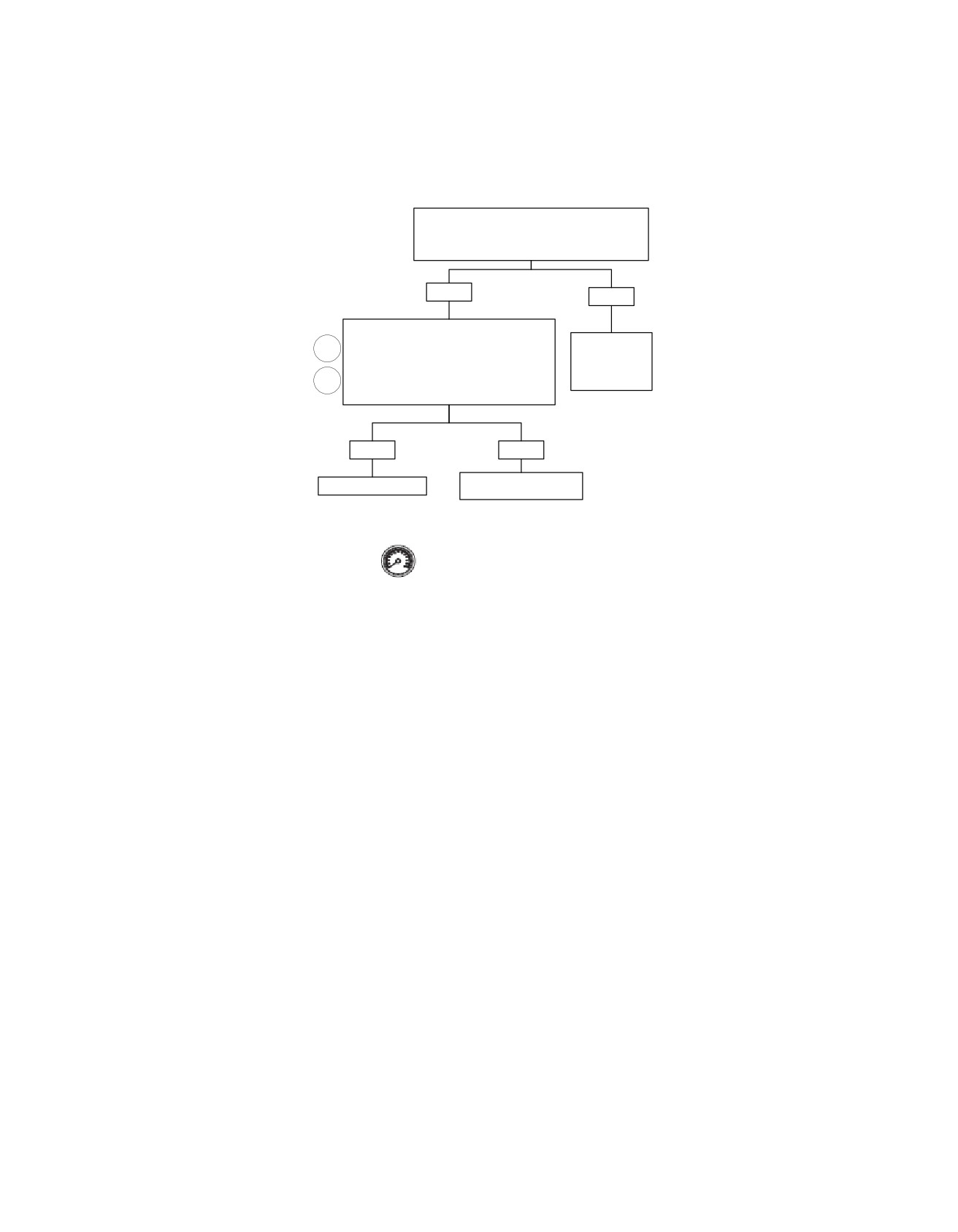
on the flow chart(s).
Figure 2-16. Trip Odometer Reset Switch Circuit
1. Disconnect speedometer connector [39] (at the back of
the speedometer). See 2.5 BREAKOUT BOX: SPEEDO-
METER/TACHOMETER.
Table 2-12. Wire Harness Connectors
NO.
DESCRIPTION
MODEL
TYPE
LOCATION
[39]
Speedometer
FLHT/C
12-place Packard
Inner fairing (back of speedometer)
FL
TR
12-place Packard
Under bezel (back of speedometer)
2-30 2008 Touring Diagnostics: Instruments
HOME
Trip Odometer Reset Switch Closed: DTC B1008
Remove Trip Odometer Reset Switch Rubber Boot.
Clear codes using 2.3 SPEEDOMETER SELF
DIAGNOSTICS.
Codes still present?
YES
NO
With speedometer connector [39B]
disconnected, measure resistance between
Replace Trip
1
terminals “8” and “11” on Breakout Box.
Odometer Reset
Resistance should be less than 1 ohm with
Switch Rubber
Trip Odometer Reset Switch depressed and
2
Boot.
infinity ohms when released.
Is it?
YES
NO
Replace Trip Odometer
Replace Speedometer.
Reset Switch.
Clear codes using speedometer self diagnostics.
See Section 4.6 SPEEDOMETER SELF DIAGNOSTICS.
Confirm proper operation with no check engine lamp.
fc01095_en
2008 Touring Diagnostics: Instruments 2-31
HOME
DTC U1016
2.12
GENERAL
Table 2-13. Code Description
Loss of ECM Serial Data
DTC
DESCRIPTION
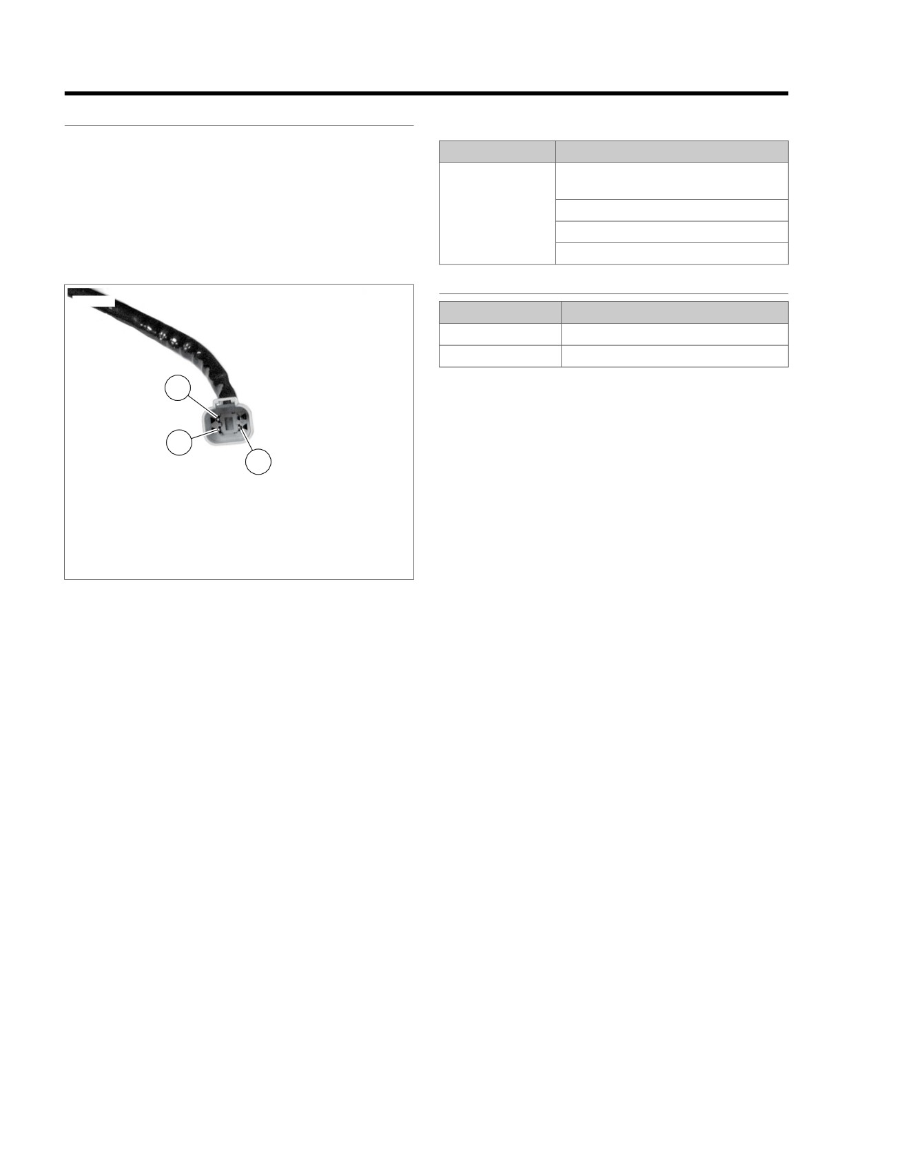
See Figure 2-17. The data link connector provides a means
U1016
Loss of all ECM serial data (state of
for the ECM, TSM/TSSM/HFSM and speedometer to commu-
health)
nicate their current status. When all operating parameters on
Loss of vehicle speed
the serial data bus are within specifications, a state of health
message is sent between the components. A DTC U1016
Loss of vehicle inhibit motion
indicates that the ECM is not capable of sending this state of
Loss of powertrain security status
health message.
DIAGNOSTICS
ed02982
PART NUMBER
TOOL NAME
HD-42682
BREAKOUT BOX
HD-43876
BREAKOUT BOX
3
Diagnostic Notes
Each reference number below correlates to a circled number
on the flow chart(s).
2
1. Connect BREAKOUT BOX (Part No. HD-42682) (gray)
1
between TSM/TSSM/HFSM connector [30A] and wire
harness connector [30B]. See 4.7 BREAKOUT BOX: EFI.
2. Connect BREAKOUT BOX (Part No. HD-43876) between
wire harness and ECM. See 4.7 BREAKOUT BOX: EFI.
1. Terminal 2: ground (BK/GN)
2. Terminal 3: serial data (LGN/V)
3. Terminal 4: power (GY)
Figure 2-17. Data Link Connector
2-32 2008 Touring Diagnostics: Instruments
HOME
Radio
em01111
15A
[1A][1B]
Instruments
9
Fuse
To
[27A]
O
1
1
O
R/BK
ignition
[27B]
9
switch
Main to interconnect
harness
LGN/V
13
13
LGN/V
To ignition fuse
GY
1
2
3
12
[30B]
1
2
5
7
[39B]
1
2
5
7
[108B]
1
2
3
12
[30A]
1
2
5
7
[39A]
1
2
5
7
[108A]
TSM/TSSM/HSFM
Speedometer
Tachometer
ABS
9
1
[166A]
9
1
[166B]
1
BK/GN
2
Data Link
LGN/V
3
Connector
GY
4
[91A]
[2B]
4
12
Main to
interconnect
[2A]
4
12
harness
69
[78B]
69
[78A]
1
2
3
5
[20B]
To
battery
fuse
ECM
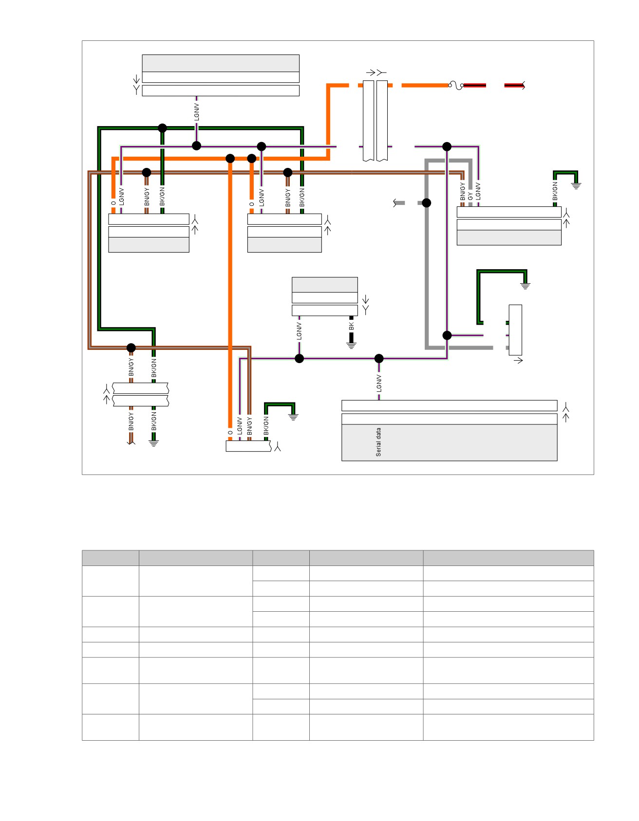
Figure 2-18. Serial Data Circuit: FLHX, FLHT/C/U, FLTR
Table 2-14. Wire Harness Connectors
NO.
DESCRIPTION
MODEL
TYPE
LOCATION
[1]
Main to interconnect har-
FLHT/C
16-place Molex (Black)
Inner fairing - right radio support bracket
ness
FLTR
16-place Molex (Black)
Inner fairing - below radio (right side)
[2]
Main to interconnect har-
FLHT/C
12-place Molex (Gray)
Inner fairing - left fairing support bracket
ness
FLTR
12-place Molex (Gray)
Inner fairing - below radio (right side)
[20]
Console harness
All
16-place Molex
Under seat
[27]
Radio
All
23-place Amp (T
yco)
Inner fairing - back of radio (right side)
[30]
TSM/TSSM/HFSM
All
12-place Deutsch
Cavity in crossmember at rear of battery
box (under seat)
[39]
Speedometer
FLHT/C
12-place Packard
Inner fairing (back of speedometer)
FLTR
12-place Packard
Under bezel (back of speedometer)
[78]
Electronic Control Module
All
73-place Packard
Under seat
(ECM)
2008 Touring Diagnostics: Instruments 2-33
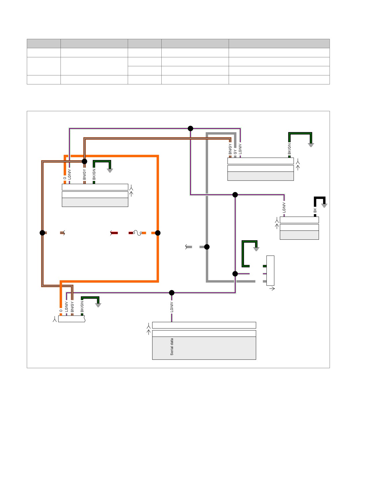
HOME
Table 2-14. Wire Harness Connectors
NO.
DESCRIPTION
MODEL
TYPE
LOCATION
[91]
Data link connector
All
4-place Deutsch
Under left side cover
[108]
T
achometer
FLHT/C
12-place Packard
Inner fairing (back of tachometer)
FL
TR
12-place Packard
Under bezel (back of tachometer)
[166]
ABS module
All
20-place Molex
Under right side cover
em01112
1
2
3
12
[30B]
1
2
3
12
[30A]
TSM/TSSM/HSFM
1
2
5
7
[39B]
1
2
5
7
[39A]
Speedometer
15A
Instruments
[166B]
9
1
Fuse
To
To
[166A]
9
1
BN/GY
battery
ignition
R/BK
O
fuse
switch
To
ABS
ignition
GY
fuse
1
BK/GN
2
Data Link
LGN/V
3
Connector
GY
4
[91A]
[20B]
1
2
3
5
[78B]
69
[78A]
69
ECM
Figure 2-19. Serial Data Circuit: FLHR/C/S
2-34 2008 Touring Diagnostics: Instruments

HOME
Table 2-15. FLHR Wire Harness Connectors
NO.
DESCRIPTION
TYPE
LOCATION
[20]
Console harness
16-place Molex
Under seat
[30]
TSM/TSSM/HFSM
12-place Deutsch
Cavity in crossmember at rear of bat-
tery box (under seat)
[39]
Speedometer
12-place Mini-Deutsch
Under console (back of speedometer)
[78]
Electronic Control Module (ECM)
73-place Packard
Under seat
[91]
Data link connector
4-place Deutsch
Under left side cover
[166]
ABS module
20-place Molex
Under right side cover
2008 Touring Diagnostics: Instruments 2-35