Harley Davidson 2008 Touring Models. Electrical Diagnostics Manual - page 2
HOME
em01117
Battery
1
1
BN/GY
Ignition
2
2
GY
Serial data link
3
3
LGN/V
Neutral switch
4
4
TN
TSM/
TSSM/
HFSM
Start relay control
9
9
TN/GN
Clutch switch
10
10
BK/R
Ground
12
12
BK/GN
Red
Band
[30A] [30B]
Battery
Electronic
Control
[78A]
[78B]
Module (ECM)
Starting System
40A
MAXIFUSE
Serial data link
69
69
LGN/V
[5B]
[
128A]
[128B]
B
A
Engine stop switch
72
72
W/BK
Starter
Right Hand
Controls
IGNITION SWITCH LEGEND
“X” INDICATES CONTINUITY
BETWEEN LEAD WIRES
SWITCH
IN POSITION INDICATED
POSITION
RED/
RED/
RED
GRAY
BLACK
Engine Stop Switch
LOCK
X
OFF
X
Starter Switch
IGN
X
X
X
BK/GN
ACC
X
X
(Black)
[1A] [1B]
Ignition
(Black)
Switch
[22A]
[22B]
Rear
Front
GND2
GND1
GY
3
3
GY
(Clean)
(Dirty)
[33B]
W/BK
4
4
W/BK
W/BK
6
6
W/BK
R/GY
1
BK/R
6
6
BK/R
R
2
GY
3
3
GY
R/BK
3
[64-2B]
(Gray)
1F
Ignition - 15A
1E
[2A] [2B]
GY
R/BK
BK/GN
12
12
BK/GN
[64-1B]
BK/R
11
11
BK/R
2D
Battery - 15A
2C
BN/GY
R
To ignition
relay
BK/R
2
2
BK/R
R/GY
3H
30
3
GN
4G
87
5
Start
BK/R
4H
86
1
Relay
TN/GN
3G
85
2
(Gray)
[24A]
[24B]
TN
BK/R
7
7
BK/R
Front GND
To instrument fuse
Stud
(Dirty)
BK
12
12
BK/GN
Clutch
13
13
14
14
Switch
15
15
[GND1A]
[21A]
6
7
16
16
16-way on all except FLHTP
[21B]
6
7
12-way on FLHTP
B
A
[131]
(BK)
Neutral
Left Hand
Switch
Neutral
Controls
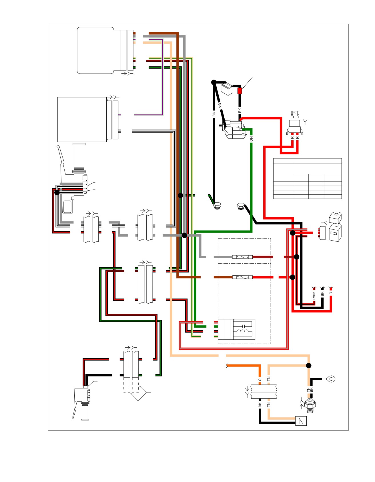
Figure 1-2. Starting Circuit (FLHX, FLHT/C/U, FLTR)
2008 Touring Diagnostics: Starting / Charging 1-5
HOME
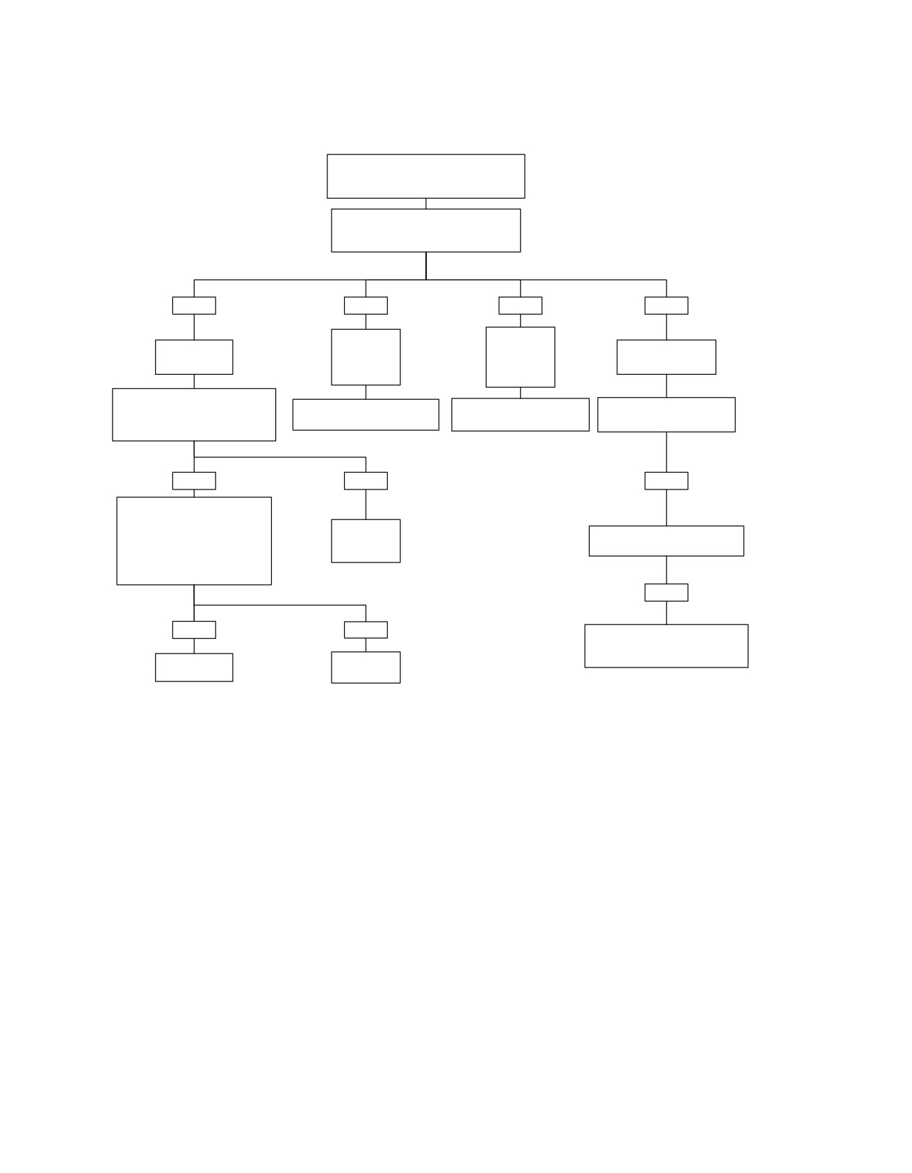
Starter Testing 1
Check Battery using visual inspection,
Voltage Test, and either Conductance Test or
Load Test.
Check connections at Battery and Starter
components.
Is system operational?
YES
YES
YES
NO
Starter
Starter
Spins, But
Stalls or
Check for audible
Starter Runs On.
Does Not
Spins Too
clicking noise.
Engage.
Slowly.
Disconnect solenoid relay terminal
from Solenoid.
See Starter Testing 5: Starter
See Starter Testing 6: Starter
Solenoid clicks. See Starter
Is 12V present on (GN) wire with
Spins, But Does Not Engage.
Stalls or Spins Too Slowly.
Testing 2: Solenoid Clicks.
Starter Button not pressed?
YES
NO
NO
Is 12V present on connector [64-1]
start relay socket terminal “86” with
starter button not pressed?
Replace
Relay clicks. See
NOTE:
Start Solenoid.
Starter Testing 3: Relay Clicks.
Depending on relay used relay
socket terminal could be shown as
5845
“1” or “4H”.
NO
YES
NO
Nothing clicks. See Starter Testing
4: Nothing Clicks (Part 1 of 2).
Replace
Replace
Starter Button.
Start Relay.
5818
5832
fc01074_en
1-6 2008 Touring Diagnostics: Starting / Charging
HOME
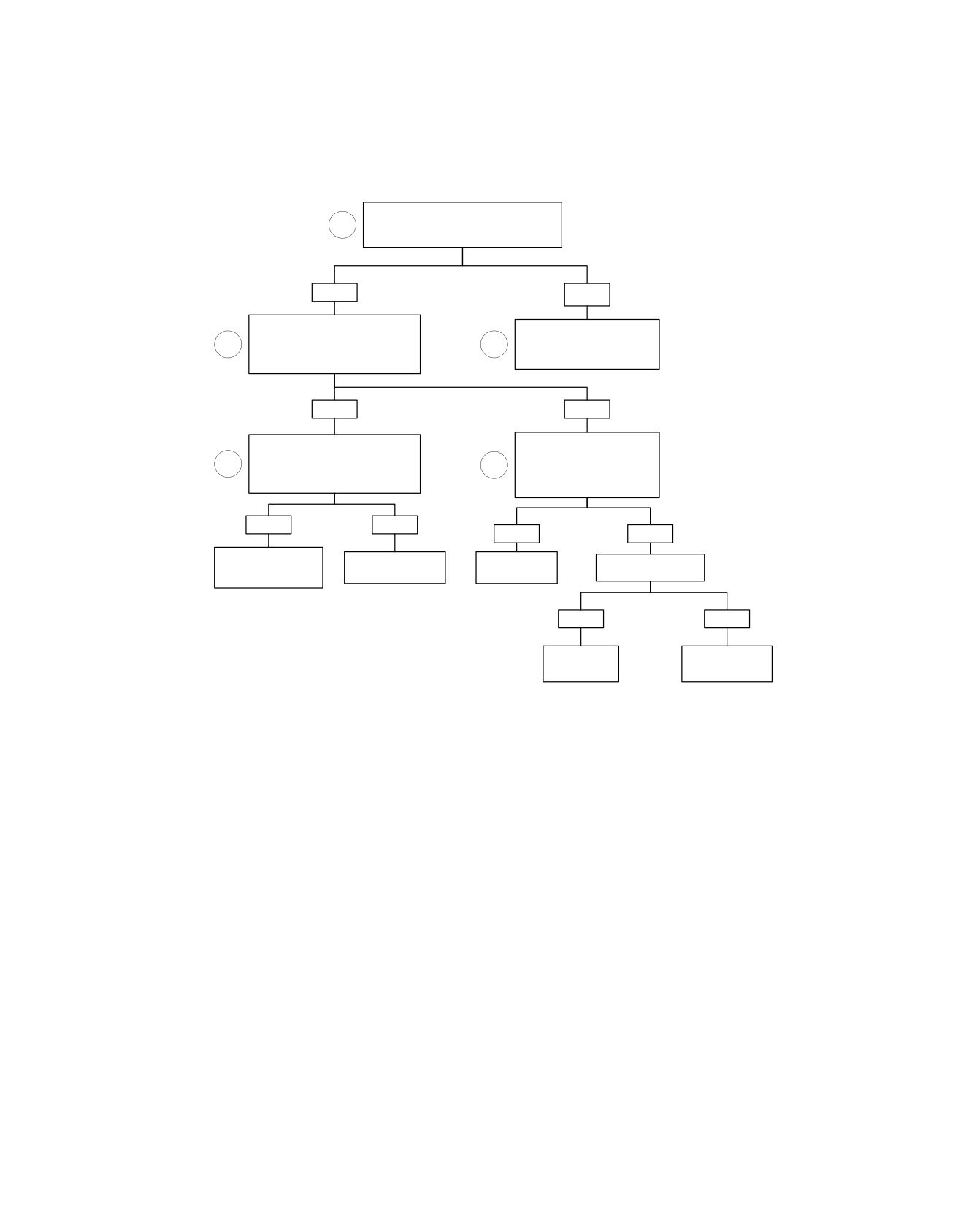
Starter Testing 2: Solenoid Clicks
Perform voltage drop test between battery
1
negative and relay terminal on Solenoid.
Is voltage drop less than 1.0 volt?
YES
NO
Perform voltage drop test from
Pinpoint poor connections or
battery positive to starter motor
1
1
relay contact problems using
terminal. Crank Engine.
voltage drop test.
Voltage greater than 1.0 volt?
5823
YES
NO
Perform voltage drop test
Perform voltage drop test from
between battery negative and
battery positive to starter battery
1
1
starter studs or bolts.
terminal. Crank Engine.
Is voltage drop greater than 1.0
Is voltage drop greater than 1.0 volt?
volt?
YES
NO
YES
NO
Repair connection
Repair or replace
Clean ground
Does Starter Motor
between Battery and
Solenoid (contacts).
connections.
turn if jumped?
Starter.
5845
5824
5824
YES
NO
Replace
Replace or repair
Solenoid.
Starter Motor.
5860
5817
fc01075_en
2008 Touring Diagnostics: Starting / Charging 1-7
HOME
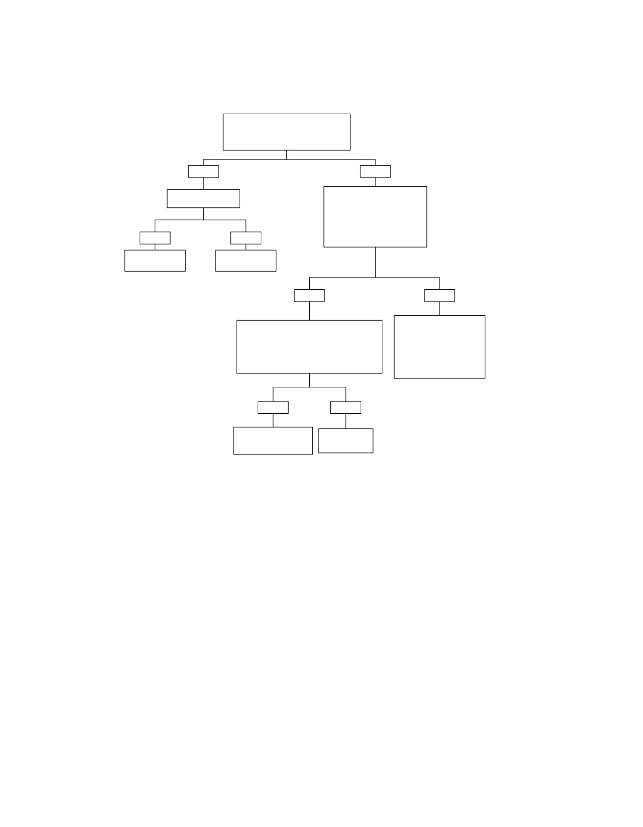
Starter Testing 3: Relay Clicks
Test for voltage at starter solenoid
terminal connector [128B] (GN).
Is 12V present when Starter Button is
pressed?
YES
NO
Does Starter Motor
Test for voltage to Start Relay.
turn if jumped?
Is 12V present on connector
[64-1] relay socket terminal “30”?
NOTE:
Depending on relay used relay
socket terminal could be shown
YES
NO
as “3” or “3H”.
5827
Replace Starter
Replace or repair
Solenoid.
Starter Motor.
5860
5817
YES
NO
Repair open on (R/BK)
Test for voltage from Start Relay.
wire feeding connector [64-1]
Is 12V present on connector [64-1] relay socket
relay socket terminal “30”.
terminal “87” when Starter Button is pressed?
NOTE:
NOTE:
Depending on relay used
Depending on relay used relay socket terminal
relay socket terminal could
could be shown as “5” or “4G”.
be shown as “3” or “3H”.
YES
NO
Repair open on (GN)
Replace
wire between Start Relay
Start Relay.
and Starter Solenoid.
fc01076_en
5827
5832
1-8 2008 Touring Diagnostics: Starting / Charging
HOME
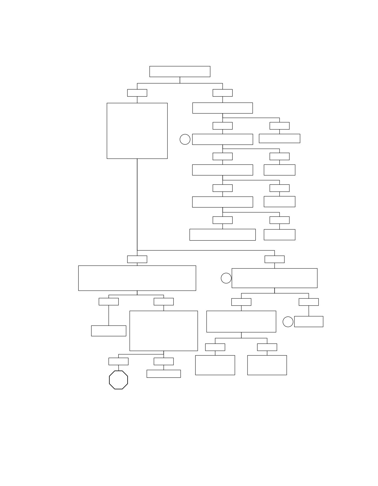
Starter Testing 4: Nothing Clicks (Part 1 of 2)
Do turn signals work properly?
YES
NO
Is TSM/TSSM/HFSM connector
Turn the Ignition Switch to
[30] fully mated?
IGNITION. With the Engine Stop
Switch in the RUN position,
depress the start switch while
checking for battery voltage at
YES
NO
start relay terminal “86”.
Is battery voltage present?
Continuity to ground on TSM/
Mate connector [30].
NOTE:
3
TSSM/HFSM terminal “12”?
Depending on relay used relay
6792
socket terminal could be shown
as “1” or “4H”.
YES
NO
Continuity on TSM/TSSM/HFSM
Repair open.
terminal “1” to battery fuse?
6805
YES
NO
Continuity on TSM/TSSM/HFSM
Repair open.
terminal “2” to IGN fuse?
6806
YES
NO
Replace TSM/TSSM/HFSM. Learn
Repair open.
password and perform set-up.
6791
6793
YES
NO
Check for continuity to chassis ground at start relay terminal “85”.
Disconnect connector [22]. Check for continuity
Is continuity present?
between terminal “4” (W/BK) and terminal “6”
NOTE:
4
(BK/R) of connector [22A].
Depending on relay used relay socket terminal could be shown as
Continuity present with start switch pressed?
“2” or “3G”.
YES
NO
YES
NO
Check for continuity from start relay
Turn the Ignition Switch to IGNITION.
terminal “85” to terminal “9” on TSM/
Check for voltage to start switch, at
Replace
7
TSSM/HFSM connector [30].
connector [22B] terminal “3” (GY).
start switch.
Substitute good
Is continuity present?
Battery voltage present?
5818
relay or test relay.
NOTE:
Depending on relay used relay
socket terminal could be shown as
“2” or “3G”.
YES
NO
Locate and repair
Locate and repair
YES
NO
open in (BK/R) wire
open in (GY) wire
from connector [22B]
from connector [22B]
Repair open.
to start relay.
to IGN fuse.
5831
5831
STOP
5828
Go to Starter Testing 4:
fc01077_en
Nothing Clicks (Part 2 of 2).
2008 Touring Diagnostics: Starting / Charging 1-9
HOME
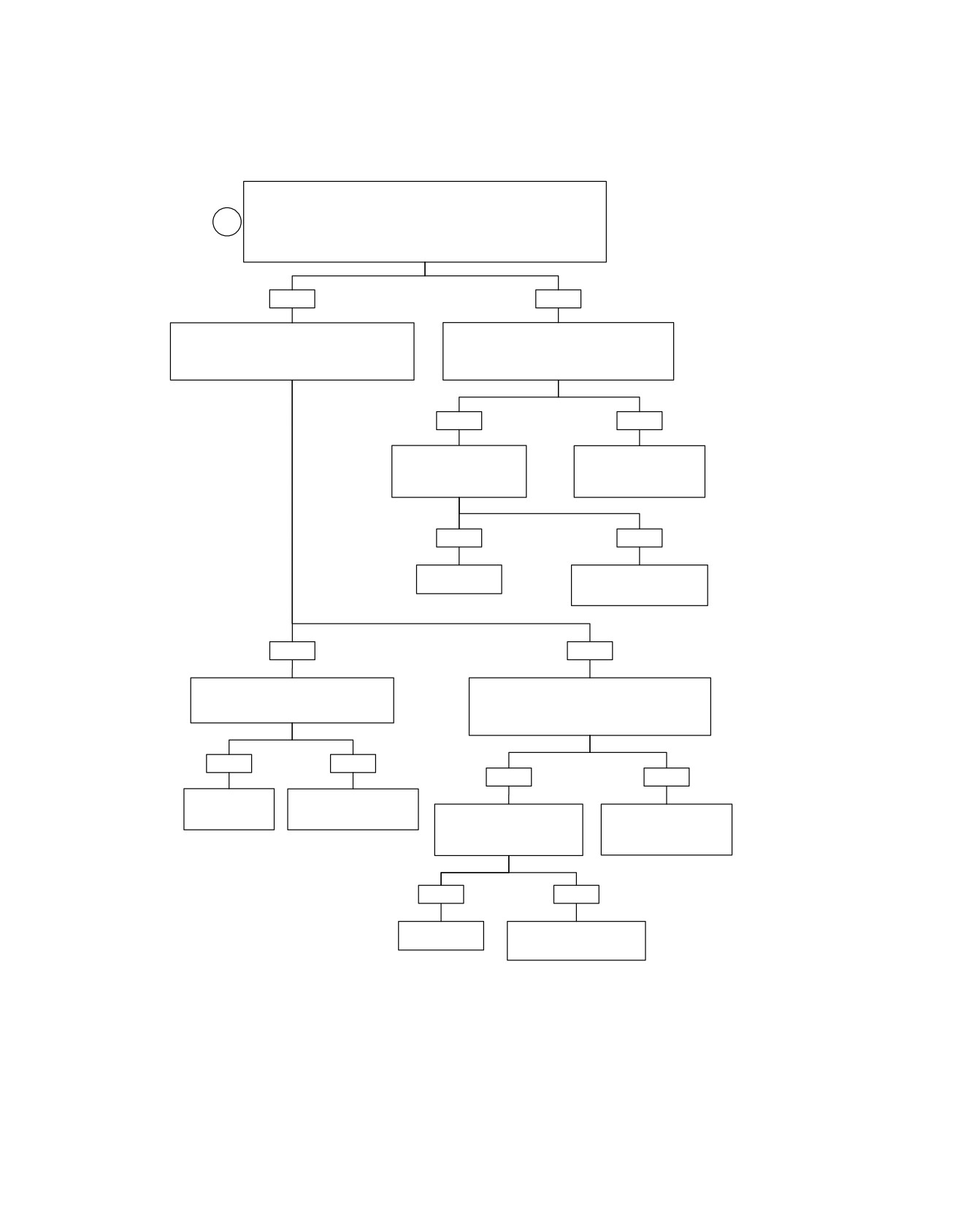
Starter Testing 4: Nothing Clicks (Part 2 of 2)
Continued from
Starter Testing 4: Nothing Clicks (Part 1 of 2).
6
Install breakout box HD-42682. Shift transmission to neutral. Measure continuity
to chassis ground at breakout box terminal “4” (Gray) (neutral switch).
Is continuity (less than 10 ohms) present?
YES
NO
Disengage clutch (pull in clutch lever). Measure
Disconnect neutral switch connector [131]. Check
continuity to chassis ground at breakout box terminal
for continuity between breakout box terminal “4”
“10” (Gray) (clutch switch) with clutch disengaged.
(Gray) and connector [131] terminal “B” (TN).
Is continuity present?
Is continuity present?
YES
NO
Check for continuity from
Locate and repair open on
connector [131] terminal “A”
(TN) wire between neutral
(BK) to chassis ground.
switch and TSM/TSSM/
Is continuity present?
HFSM.
5862
YES
NO
Replace Neutral
Locate and repair open on
Switch.
(BK) wire between neutral
5157
switch and ground.
YES
NO
Turn Ignition Switch to IGNITION. Check for
Disconnect left hand controls connector [24]. Check
voltage on breakout box terminal “9” (Gray).
for continuity between breakout box terminal “10”
Is voltage present?
(Gray) and connector [24B] terminal “7” (BK/R).
Is continuity present?
YES
NO
YES
NO
Locate and repair
Replace TSM/TSSM/HFSM.
short to voltage on
Learn password and
Check for continuity from
Locate and repair open on
(TN/GN).
perform set-up.
connector [24B] terminal “8”
(BK/R) wire between clutch
5830
5838
(BK/GN) to chassis ground.
switch and TSM/TSSM/
Is continuity present?
HFSM.
YES
NO
Replace Clutch
Locate and repair open on
Switch.
(BK/GN) wire between clutch
switch and ground.
5168
5861
fc01648_en
1-10 2008 Touring Diagnostics: Starting / Charging
HOME
Starter Testing 5: Starter Spins, But Does Not Engage
Remove Starter. Disassemble Drive Housing
Assembly. Inspect for damage to Armature
Gear or Idler Gear.
Damage present?
YES
NO
Replace damaged Idler
Starter Clutch failure.
Gear and Armature.
Replace Starter Clutch.
5825
5837
fc01079_en
2008 Touring Diagnostics: Starting / Charging 1-11
HOME
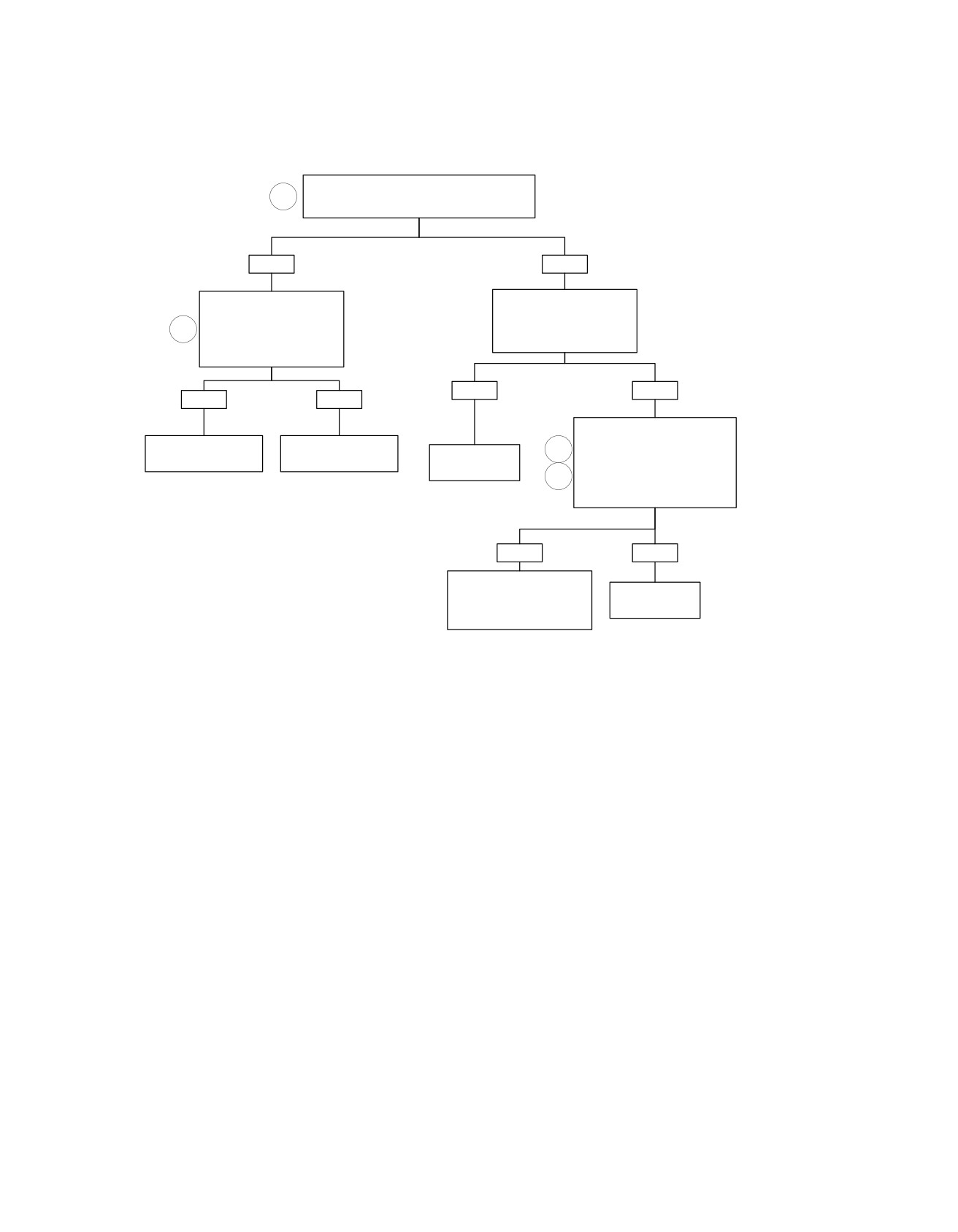
Starter Testing 6: Starter Stalls or Spins Too Slowly
Perform voltage drop test from battery positive to
1
starter motor terminal. Crank Engine.
Voltage greater than 1.0 volt?
YES
NO
Perform voltage drop test
Perform voltage drop test
between battery positive to
between battery negative and
starter battery terminal.
starter studs or bolts.
1
Is voltage drop greater than 1.0
Crank Engine.
Is voltage drop greater than 1.0
volt?
volt?
YES
NO
YES
NO
Perform starter motor current
Repair connection
draw test (on vehicle).
Repair or replace
5
between Battery and
Solenoid (contacts).
Clean Ground
Starter.
Perform starter motor free running
connections.
6
current draw bench test.
5824
5845
5835
Are test results within range?
YES
NO
Remove Spark Plugs. While in
5th gear, rotate rear wheel.
Replace or repair
Check for Engine, Primary
Starter Motor.
and/or Crankshaft bind.
5817
Use appropriate code
fc01080_en
1-12 2008 Touring Diagnostics: Starting / Charging
HOME
DIAGNOSTICS/TROUBLESHOOTING
1.3
until the source of the potential difference is found. The
VOLTAGE DROP
benefits of doing it this way are speed and accuracy.
Check the integrity of all wiring, switches, fuses and connectors
a. Readings are not as sensitive to real battery voltage.
between the source and destination.
b. Readings show the actual voltage dropped, not just
The voltage drop test measures the difference in potential or
the presence of voltage.
the actual voltage dropped between the source and destination.
c. This tests the system as it is actually being used. It
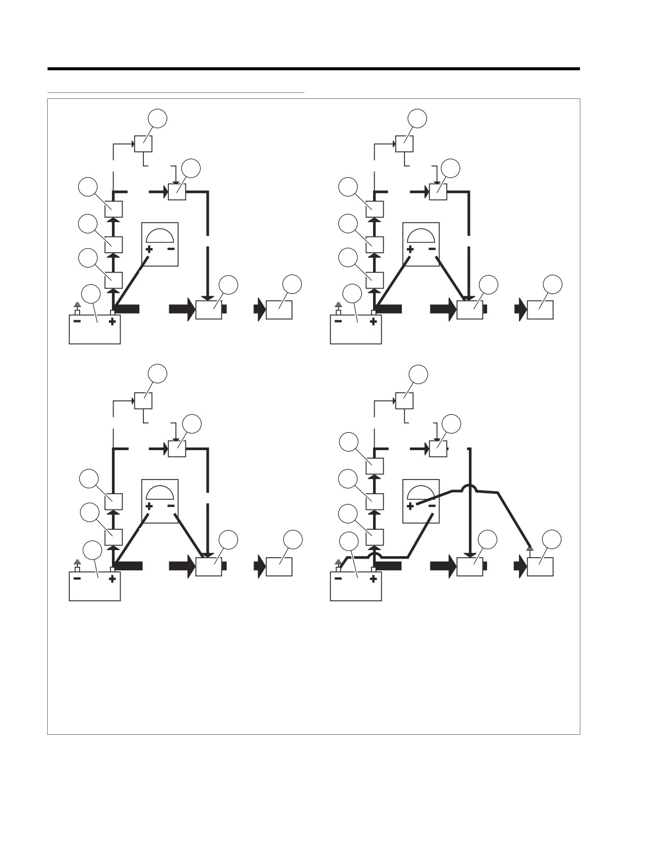
1. See ITEM A in Figure 1-3. Attach your red meter lead to
is more accurate and will display hard to find poor
the most positive part of the circuit, which in this case
connections.
would be the positive post of the battery (5).
d. This approach can be used on lighting circuits, ignition
2. See ITEM B in Figure 1-3. Attach the black meter lead to
circuits, etc. Start from most positive and go to most
the final destination or component in the circuit (solenoid
negative (the destination or component).
terminal from relay).
3. Activate the starter and observe the meter reading. The
6.
See ITEM D in Figure 1-3. The negative or ground circuit
meter will read the voltage dropped or the difference in
can be checked as well.
potential between the source and destination. An ideal
a. Place the negative lead on the most negative part of
circuit's voltage drop would be
0 volt or no voltage
the circuit (or the negative battery post). Remember,
dropped, meaning no difference in potential.
there is nothing more negative than the negative post
of the battery.
4. See ITEM C in Figure 1-3. An open circuit should read 12
volts, displaying all the voltage dropped, and the entire
b. Place the positive lead to the ground you wish to
difference in potential displayed on the meter.
check.
NOTE
c. Activate the circuit. This will allow you to read the
Open circuits on the ground side will read zero.
potential difference or voltage dropped on the neg-
ative or ground circuit. This technique is very effective
5. Typically, a good circuit will drop less than 1.0 volt. If the
for identifying poor grounds due to powdered paint.
voltage drop is greater, back track through the connections
Even the slightest connection may cause an ohm-
meter to give a good reading. However, when suffi-
cient current is passed through, the resistance caused
by the powdered paint will cause a voltage drop or
potential difference in the ground circuit.
2008 Touring Diagnostics: Starting / Charging 1-13
HOME
STARTER ACTIVATION CIRCUITS
1.4
STARTER ACTIVATION CIRCUITS
ed02788
1
1
ITEM A
ITEM B
0.1A
0.1A
0.1A
0.1A
IDEAL CLOSED
2
2
CIRCUIT
8
8
20A
20A
7
7
OV
20A
20A
6
6
VDC
3
4
3
4
5
5
200A
200A
200A
200A
1
1
ITEM C
ITEM D
0.1A
0.1A
2
OPEN CIRCUIT
0.1A
0.1A
2
GROUND CIRCUIT
8
20A
20A
20A
VDC
7
7
12V
OV
20A
6
6
VDC
3
4
5
3
4
5
200A
200A
200A
200A
1. Start switch
2. Relay
3. Solenoid
4. Starter
5. Battery
6. MAXIFUSE
7. Ignition switch
8. Ignition fuse
Figure 1-3. Typical Circuitry. Refer to wiring diagrams for more information.
1-14 2008 Touring Diagnostics: Starting / Charging
HOME
TESTING STARTER ON MOTORCYCLE
1.5
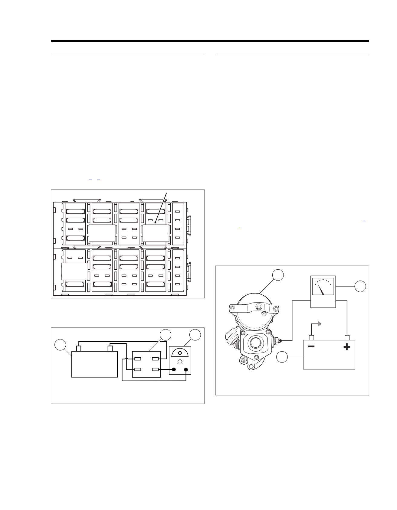
START RELAY TEST
STARTER CURRENT DRAW TEST
1. See Figure 1-4. Locate the start relay behind the left side
NOTES
cover.
•
Engine temperature should be stable and at room temper-
2. See Figure 1-5. The start relay can be tested using the
ature.
motorcycle's 12 volt battery and a multimeter.
•
Battery should be fully charged.
a. Unplug connector from relay.
See Figure 1-6. Check starter current draw with an induction
b. To energize relay, connect the "85"(2) and relay ter-
ammeter before disconnecting battery. Proceed as follows:
minal "86"(1) to the positive battery terminal.
1. Verify that transmission is in neutral. Disconnect spark
c. Check for continuity between the 30 (3) and 87 (5)
plug wires from spark plug terminals.
terminals. A good relay shows continuity (continuity
2. Clamp induction ammeter over positive battery cable next
tester lamp "on" or a zero ohm reading on the ohm-
to starter.
meter). A malfunctioning relay will not show continuity
and must be replaced.
3. With ignition switch to IGNITION, turn engine over by
pressing starter switch while reading the ammeter. Dis-
3. If start relay is functioning properly, proceed to
regard initial high current reading which is normal when
1.5 TESTING STARTER ON MOTORCYCLE, Starter
engine is first turned over.
Current Draw Test.
a. Typical starter current draw will range between 160
to 200 amperes.
ed01343
b. If starter current draw exceeds 250 amperes, then
A
C
E
G
J
64-1B
the problem may be in the starter or starter drive.
1
15A
15A
15A
15A
Remove starter for further tests. See 1.6 TESTING
2
15A
15A
15A
STARTER ON BENCH, Free Running Current Draw
85
30
85
30
Test.
3
4
15A
87
86
87
86
NOTE
B
D
F
H
A DC current probe may be used if an induction ammeter is
A
C
E
G
J
64-2B
1
15A
15A
15A
not available.
85
30
2
15A
15A
15A
ed02864
3
1
87
86
4
30A
15A
30A
2
B
D
F
H
Figure 1-4. Start Relay
ed01000
3
1
2
-
+
30
(3)
85
(2)
3
86
(1)
87
(5)
1. Starter
2. Induction Ammeter
1. Ohmmeter
3. Battery
2. Battery
3. Start relay
Figure 1-6. Starter Current Draw Test
Figure 1-5. Start Relay Test
2008 Touring Diagnostics: Starting / Charging 1-15
HOME
TESTING STARTER ON BENCH
1.6
FREE RUNNING CURRENT DRAW TEST
STARTER SOLENOID
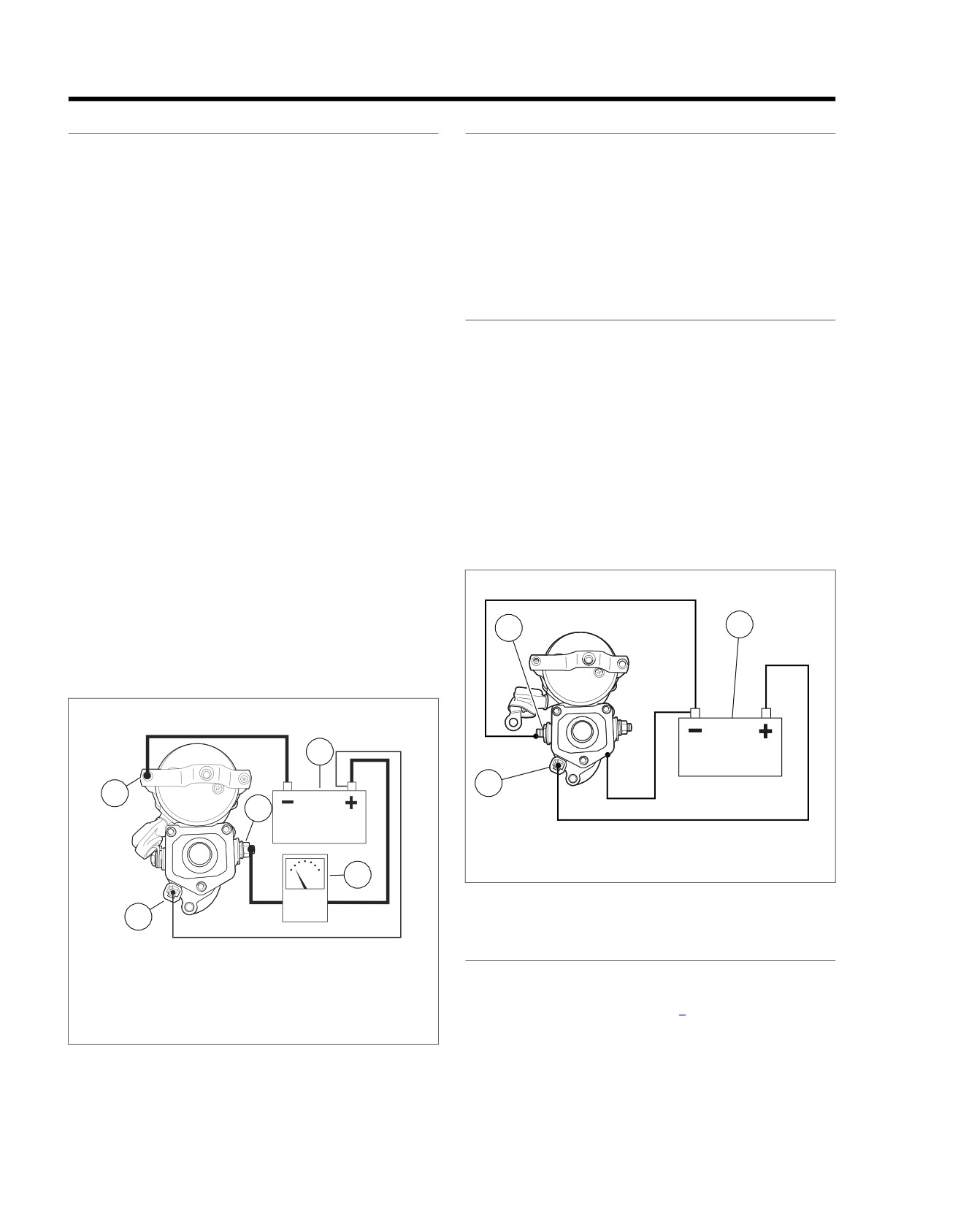
1.
Place starter in vise, using a clean shop towel to prevent
Do not disassemble solenoid. Before testing, disconnect field
scratches or other damage.
wire from motor terminal as shown in Figure 1-8.
2.
See Figure 1-7. Attach one heavy jumper cable (6 gauge
Each test should be performed for only 3-5 seconds to prevent
minimum).
damage to solenoid.
a. Connect one end to the starter mounting flange (1).
The solenoid Pull-in, Hold-in, and Return tests must be per-
formed together in one continuous operation. Conduct all three
b. Connect the other end to the negative (-) terminal of
tests one after the other in the sequence given without interrup-
a fully charged battery (2).
tion.
3.
Connect a second heavy jumper cable (6 gauge minimum).
SOLENOID PULL-IN TEST
a. Connect one end to the positive (+) terminal of the
1. See Figure 1-8. Using a 12 volt battery, connect three
battery (2).
separate test leads as follows:
b. Connect the other end to the battery terminal (4) on
a. Solenoid housing to negative battery post.
the starter solenoid. Place an inductive ammeter (3)
over cable.
b. Solenoid motor terminal to negative battery post.
c. Solenoid relay terminal to positive battery post.
4.
Connect a smaller jumper cable (14 gauge minimum).
a. Connect one end to the positive (+) terminal of the
2. Observe starter shaft.
battery (2).
a. If starter shaft extends strongly, solenoid is working
b. Connect the other end to the solenoid relay terminal
properly.
(5).
b. If starter shaft does not extend strongly, replace the
solenoid.
5.
Check ammeter reading.
a. Ammeter should show 90 amps maximum.
b. If reading is higher, disassemble starter for inspection.
ed00204
See the Service Manual.
c. If starter current draw on vehicle was over 200 amps
1
3
and this test was within specification, there may be a
problem with engine or primary drive.
ed02865
A
2
B
2
C
1
4
1. Motor terminal
2. Relay terminal
3
3. Battery
Figure 1-8. Pull-In Test
5
SOLENOID HOLD-IN TEST
1. Mounting flange
1. See Figure 1-9. With test leads still connected in the
2. Battery
manner specified in the previous 1.6 TESTING STARTER
3. Induction ammeter
ON BENCH, Solenoid Pull-In Test, disconnect solenoid
4. Battery terminal
motor terminal/battery negative test lead at negative bat-
5. Relay terminal
tery post only; reconnect loose end of this test lead to
Figure 1-7. Free Running Current Draw Test
positive battery post instead.
1-16 2008 Touring Diagnostics: Starting / Charging
HOME
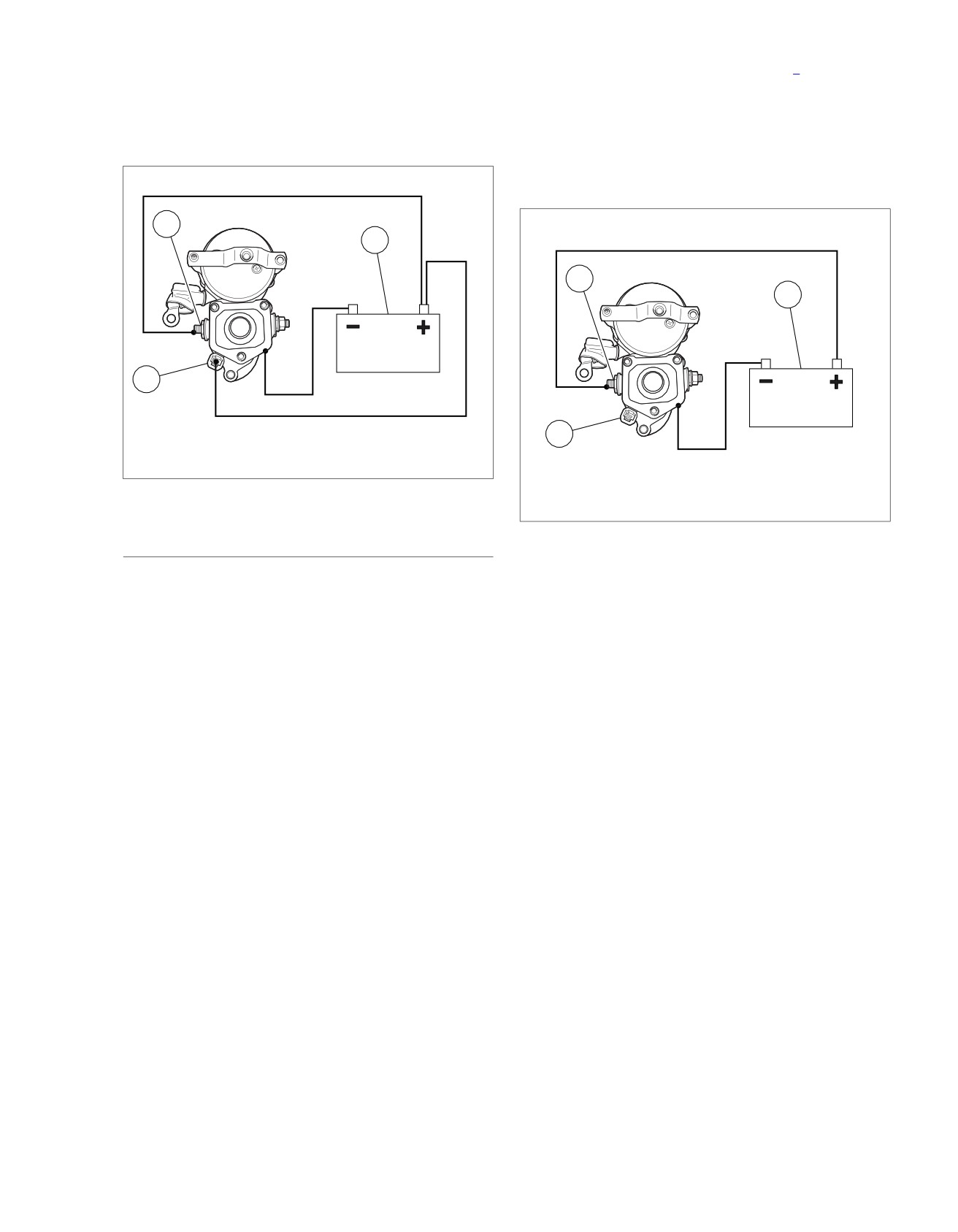
2. Observe starter shaft.
STARTER ON BENCH, Solenoid Hold-In Test, disconnect
solenoid relay terminal/positive battery post test lead at
a. If starter shaft remains extended, solenoid is working
either end.
properly.
2. Observe starter pinion.
b. If starter shaft retracts, replace the solenoid.
a. If starter shaft retracts, solenoid is working properly.
b. If starter shaft does not retract, replace the solenoid.
ed00205
1
ed00206
3
1
3
A
B
2
C
A
B
1. Motor terminal
2
C
2. Relay terminal
3. Battery
1. Motor terminal
Figure 1-9. Hold-In Test
2. Relay terminal
3. Battery
Figure 1-10. Return Test
SOLENOID RETURN TEST
1. See Figure 1-10. With test leads still connected in the
manner specified at the end of the previous 1.6 TESTING
2008 Touring Diagnostics: Starting / Charging 1-17
HOME
CHARGING SYSTEM
1.7
GENERAL
TROUBLESHOOTING
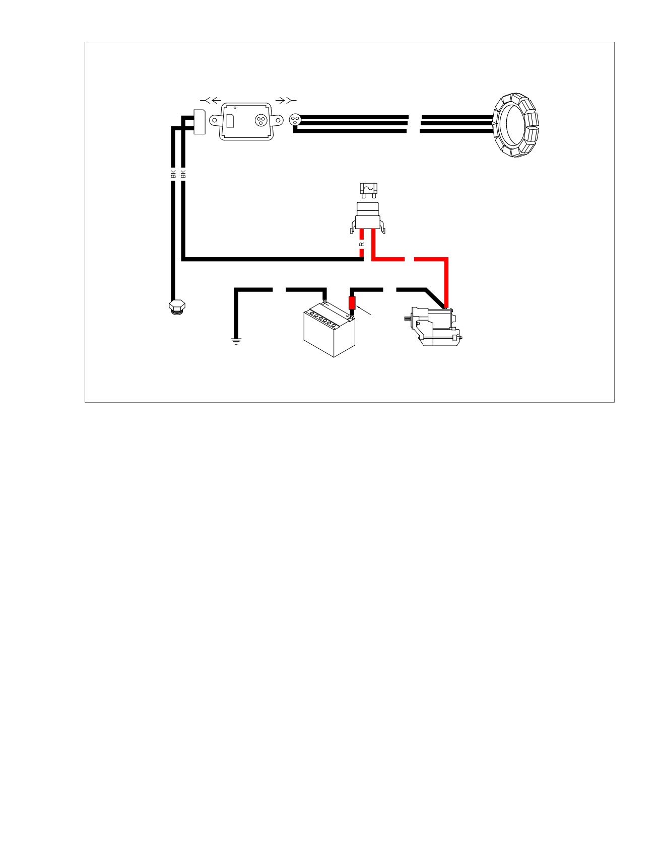
The charging system consists of the alternator and voltage
PART NUMBER
TOOL NAME
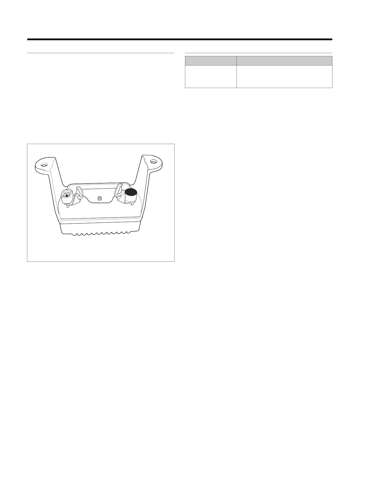
regulator. Charging system circuits are shown in Figure 1-12.
HD-48053
ADVANCED BATTERY CONDUCT-
Alternator
ANCE AND ELECTRICAL SYSTEM
ANALYZER
The alternator consists of two main components:
When the charging system fails to charge or does not charge
•
The rotor which mounts to the engine sprocket shaft.
at a satisfactory rate, make the following recommended checks.
•
The stator which bolts to the engine crankcase.
Battery
Voltage Regulator
Check for a weak or dead battery. See 1.8 BATTERY TESTING
See Figure 1-11. The voltage regulator is a series regulator.
for battery testing procedures. Battery must be fully charged
The circuit combines the functions of rectifying and regulating.
in order to perform a load test, or starting or charging tests.
However, a partially discharged battery may be tested using
the BATTERY TEST function of the ADVANCED BATTERY
ed02026
CONDUCTANCE AND ELECTRICAL SYSTEM ANA-
LYZER (Part No. HD-48053).
Wiring
The stator and battery plug and socket connections must be
clean and tight.
See Figure 1-12. Check for corroded or loose connections in
the charging circuit.
1
2
Voltage Regulator Inspection
The voltage regulator must have a clean, tight connection for
proper operation. Check by using an ohmmeter with one lead
on chassis ground, such as battery ground cable, and the other
on the voltage regulator ground lead.
1. Stator (AC) Connector [47A]
2. Voltage Regulator (DC) Connector [77A]
Job/Time Code Values
Figure 1-11. Voltage Regulator (Bottom View) AC and DC
Dealership technicians filing warranty claims should use the
Connectors
job/time code values printed in bold text underneath the
appropriate repair.
1-18 2008 Touring Diagnostics: Starting / Charging
HOME
em00176
Stator
[77B] [77A]
[47A] [47B]
2
+
BK
-
BK
1
DC
AC
BK
40 A
MAXIFUSE
B A
R
BK
BK
Red
Front
Band
Dirty GND
Powertrain
Battery
Starter
Grounds
Figure 1-12. Charging System Circuit (Typical)
2008 Touring Diagnostics: Starting / Charging 1-19
HOME
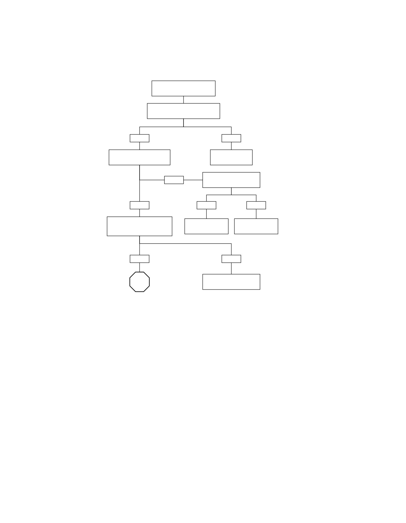
Charging System Test (Part 1 of 2)
Test Battery.
Charge or replace as required.
Inspect Voltage Regulator.
See Voltage Regulator Inspection.
PASS
FAIL
Perform MILLIAMPERE DRAW
Correct as
TEST.
required.
5306
Disconnect Regulator.
FAIL
Does milliamp draw drop?
PASS
YES
NO
Perform TOTAL CURRENT
Replace grounded
Isolate damaged
DRAW TEST.
Stator.
component or wiring.
Record measurement.
5312
5308
PASS
FAIL
Isolate damaged wiring or
STOP
excessive accessories.
5310
Go to Charging
System (Part 2 of 2).
fc01081_en
1-20 2008 Touring Diagnostics: Starting / Charging
HOME
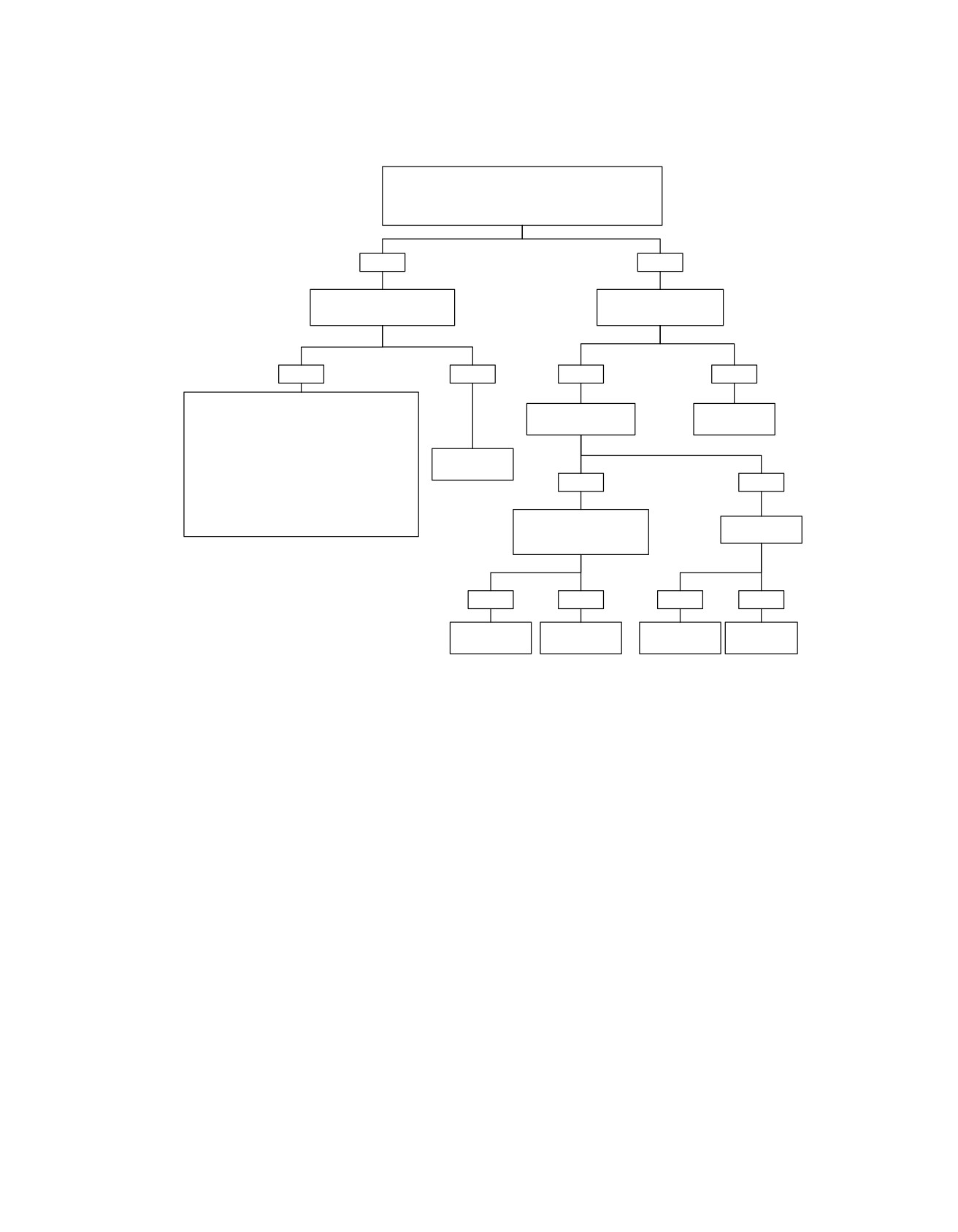
Charging System Test (Part 2 of 2)
From Charging System (Part 1 of 2).
Perform CURRENT and VOLTAGE OUTPUT TEST.
Record measurement and compare with TOTAL CURRENT
DRAW TEST before proceeding.
PASS
FAIL
Perform
Is voltage less than 15.0V?
STATOR CHECK.
YES
NO
PASS
FAIL
System tests good up to this point. Suspect:
Perform
Replace
Accessories on for long periods when vehicle is
AC OUTPUT CHECK.
Stator.
parked and not running.
5312
Replace Voltage
Accessories on when vehicle is ridden very slowly
Regulator.
for long periods.
PASS
FAIL
5316
Battery self-discharge and/or accessory draw
because vehicle was not operated for a long
Replace Voltage Regulator.
period.
Perform CURRENT and
Inspect Rotor.
VOLTAGE OUTPUT TEST.
NOTE:
Whenever a charging system component fails a test and
5315
is replaced, retest the system to be sure the problem has
been corrected.
PASS
FAIL
PASS
FAIL
Replace
System OK.
Damaged Rotor.
Replace Stator.
Rotor.
5319
5314
5319
fc01082_en
2008 Touring Diagnostics: Starting / Charging 1-21
HOME
TESTING
ed02989
1
PART NUMBER
TOOL NAME
HD-41404-B
HARNESS CONNECTOR TEST KIT
1
2 3
HD-48053
ADVANCED BATTERY CONDUCT-
[47A]
ANCE AND ELECTRICAL SYSTEM
ANALYZER
3
Milliampere Draw Test
-
+
[77A]
-
+
[77B]
NOTES
•
Be sure accessories are not wired so they stay on at all
2
times. This condition could drain battery completely if
BK
vehicle is parked for a long time. Check for this by con-
[5B]
A
B
necting ammeter between negative battery terminal and
battery.
R
•
TSM/TSSM/HFSM will continue to draw 16-25 mA for 30
seconds after ignition is turned OFF. Any disruption and
[GND2]
R
reconnection of battery power, such as disconnecting the
battery to place a meter in series, will cause TSM/TSSM/
HFSM to draw 16-25 mA for 30 seconds.
R
Disconnect siren during milliamperes draw test. (Siren may
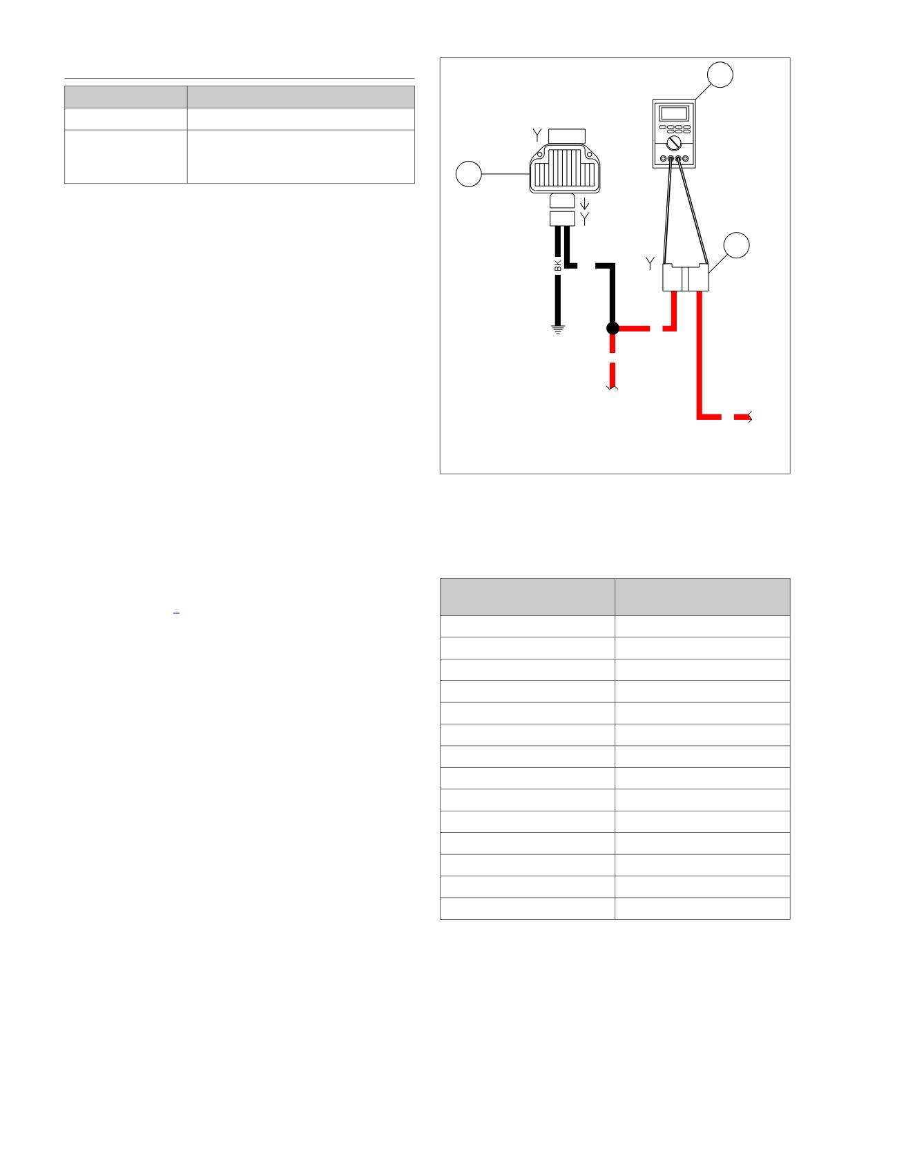
1. Ammeter
draw up to 20 mA.)
2. MAXIFUSE socket
1. Remove left side cover. Remove MAXIFUSE.
3. Voltage regulator
2. See Figure 1-13. Using HARNESS CONNECTOR TEST
Figure 1-13. Milliampere Draw Test (Ignition Turned to
KIT (Part No. HD-41404-B) red male socket probes and
OFF)
patch cords, connect ammeter to MAXIFUSE socket ter-
minals. With this arrangement, you will also pick up any
regulator drain.
Table 1-4. Milliampere Draw Test
3. With ignition switch turned to OFF and all lights and
accessories off, observe current reading.
ITEM
MAXIMUM DRAW
IN MILLIAMPERES
a. Refer to Table 1-4. Add regulator draw ammeter
reading to appropriate value for TSM/TSSM/HFSM/
ECM
1.0
ECM. If observed ammeter reading is less than listed
Speedometer
1.0
in table, draw is within limits.
T
achometer
1.0
b. A higher reading indicates excessive current draw.
TSM (no security)
1.0
Any accessories must be considered and checked
for excessive drain.
TSSM (armed)
3.0
TSSM (disarmed)
3.0
NOTE
TSSM (storage mode)
1.0
A battery with a surface discharge condition could suffer a
static drain. Correct by cleaning battery case.
HFSM
1.0
Security Siren (optional)
20.0*
Voltage Regulator
2.0
Radio
2.0
High Output Amplifier
1.0
CB Module
1.0
XM Module
1.0
* Siren will draw for 2-24 hours from time motorcycle battery
is connected and 0.05 milliamperes once siren battery is
charged. Disconnect siren during milliampere draw test.
Total Current Draw Test
If battery runs down during use, the current draw of the
motorcycle components and accessories may exceed output
of the charging system.
1-22 2008 Touring Diagnostics: Starting / Charging
HOME
NOTE
Follow the instructions in the analyzer's instruction manual to
perform a Charging System Test.
If a load tester is unavailable, an ammeter with current probe
may be used.
See Figure 1-15. The test results will include a decision on the
charging system's condition and the measured system voltage
at idle and at 3000 RPM. The analyzer's printer will provide
you with a printout including one of two possible test results:
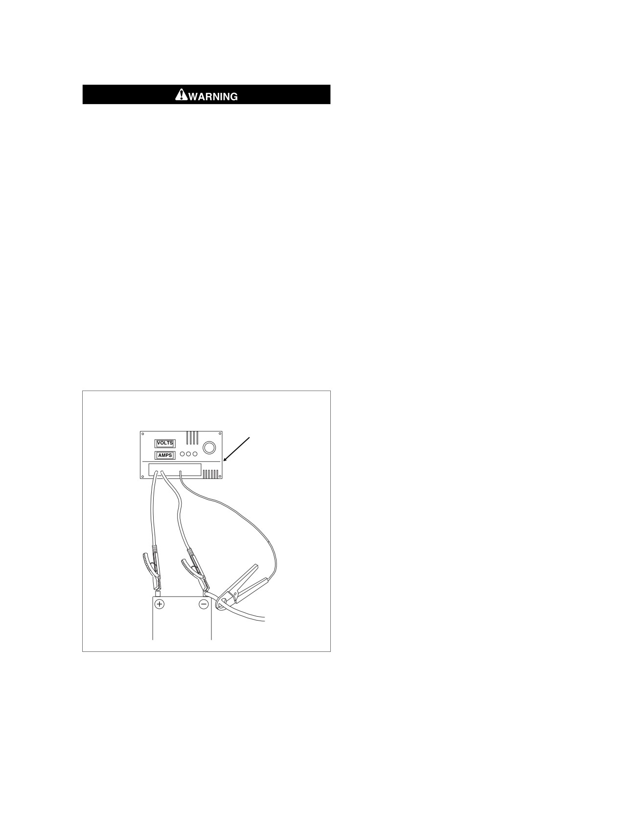
Turn battery load tester OFF before connecting tester
1. CHARGING SYSTEM NORMAL - No problem found.
cables to battery terminals. Connecting tester cables with
load tester ON can cause a spark and battery explosion,
2. CHARGING SYSTEM PROBLEM - The analyzer detected
which could result in death or serious injury. (00252a)
a problem and will display one of the three following res-
ults:
1. See Figure 1-14. To check for this condition, place load
tester induction pickup or current probe pickup over battery
a. LOW CHARGING VOLTS - The alternator is not
negative cable.
supplying sufficient current for the system's electrical
loads.
2. Disconnect stator plug from voltage regulator. Start the
motorcycle and run the engine at 2000 RPM.
b. HIGH CHARGING VOLTS - The voltage output from
the alternator exceeds the normal regulator limits.
3. With ignition and all continuously running lights and
accessories turned on (headlamp on high beam), read the
c. INVESTIGATE VOLT OUTPUT - The rev voltage is
total current draw.
lower than the idle voltage.
4. Compare this reading to the reading obtained after per-
Current and Voltage Output Test: Using
forming the CURRENT AND VOLTAGE OUTPUT TEST.
Load Tester
a. The current output should exceed current draw by
3.5 amps minimum.
1. See Figure 1-14. Connect load tester.
a. Connect negative and positive leads to battery ter-
b. If output does not meet specifications, there may be
minals.
too many accessories for the charging system to
handle.
b. Place load tester induction pickup over positive regu-
lator cable.
5. Reconnect voltage regulator after testing.
2. Run the engine at 3000 RPM. Increase the load as
required to obtain a constant 13.0VDC. Do not leave any
ed02990
load switch turned on for more than 20 seconds or over-
heating and tester damage are possible.
3. The current output should be 35-50 amps. Make note of
measurement for use in TOTAL CURRENT DRAW TEST.
NOTE
Rider's habits may require output test at lower RPM.
4. See Figure 1-14. After removing the load, read the load
tester voltage meter.
a. If voltage to the battery is not more than 15V, voltage
output is within specifications. Investigate other pos-
sible problems. See Charging System Test.
b. If voltage is higher, voltage regulator is not functioning
properly.
Figure 1-14. Check Durrent Draw (Ignition Switch On)
Current and Voltage Output Test: Using
HD-48053
Connect ADVANCED BATTERY CONDUCTANCE AND
ELECTRICAL SYSTEM ANALYZER (Part No. HD-48053) to
the vehicle's battery.
2008 Touring Diagnostics: Starting / Charging 1-23
HOME
ed02804
ed02027
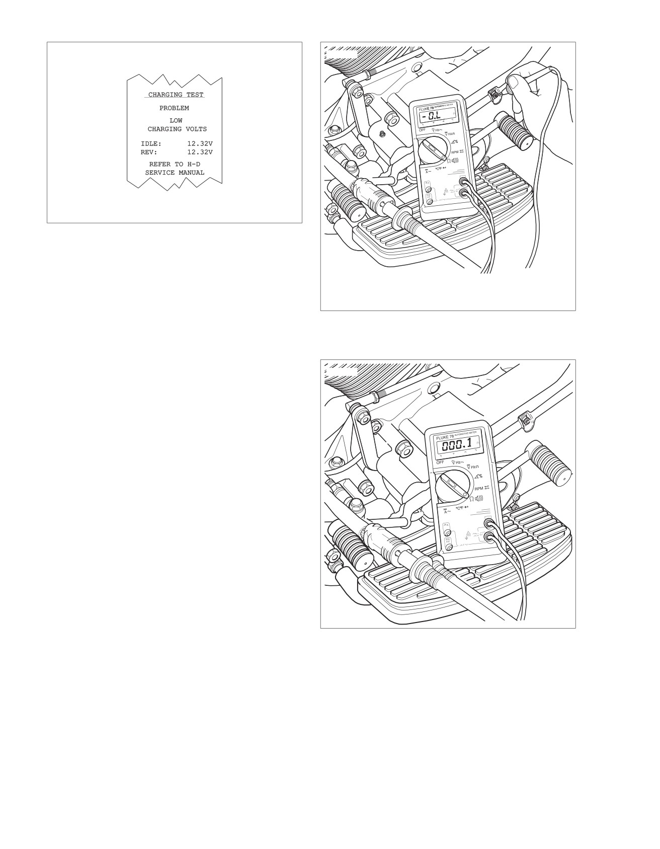
Figure 1-15. Charging System Test Results Printout
Stator Check
1. Turn ignition switch OFF.
2. See Figure 1-16. Connect an ohmmeter.
a. Disconnect voltage regulator connector from alternator
Figure 1-16. Test for Grounded Stator (Typical)
stator wiring.
b. Insert one ohmmeter lead into a stator connector
socket.
ed02028
c. Attach the other lead to a suitable ground.
3. Test for continuity with ohmmeter set to the ohms scale.
a. A good stator will show no continuity (open circuit)
between any stator sockets and ground.
b. Any other reading indicates a grounded stator which
must be replaced.
4. See Figure 1-17. Remove ground lead. Check resistance
across stator sockets 1-2, 2-3 and 3-1.
5. Test for resistance with ohmmeter set on the ohms scale.
a. Resistance across all the stator sockets should be
0.1-0.2 ohms.
b. If the resistance is higher, the stator is damaged and
must be replaced.
c. If the resistance is lower, it could indicate turn to turn
short.
NOTE
Verify that meter reads 0 ohms when probes are shorted
together. If not, subtract lowest value to resistance value of
Figure 1-17. Check for Stator Resistance (Typical)
stator.
1-24 2008 Touring Diagnostics: Starting / Charging