Harley Davidson 2008 Touring Models. Electrical Diagnostics Manual - page 1
ABOUT THIS MANUAL
GENERAL
NOTES
•
To avoid unnecessary disassembly, carefully read all rel-
This electrical diagnostic service manual has been prepared
ative service information before repair work is started.
with two purposes in mind. First, it will acquaint the user with
the construction of the Harley-Davidson product and assist in
•
In figure legends, the number which follows the name of
the performance of repair. Secondly, it will introduce to the
a part indicates the quantity necessary for one complete
professional Harley-Davidson Technician the latest field-tested
assembly.
and factory-approved diagnostic methods. We sincerely believe
•
When servicing a vehicle equipped with the Harley-Dav-
that this manual will make your association with Harley-Dav-
idson Smart Security System (H-DSSS), you must first
idson products more pleasant and profitable.
disarm the security system. Either keep the fob in close
HOW TO USE YOUR SERVICE MANUAL
proximity to the vehicle, or use Digital Technician to disable
the security system while the vehicle is being serviced and
Refer to the table below for the content layout of this manual.
re-enable the system after service is completed.
NO.
CHAPTER
SERVICE BULLETINS
1
Starting / Charging
In addition to the information presented in this Service Manual,
2
Instruments
Harley-Davidson Motor Company will periodically issue Service
Bulletins to Harley-Davidson dealers. Service Bulletins cover
3
TSM/HFSM
interim engineering changes and supplementary information.
4
Engine Management
Consult the Service Bulletins to keep your product knowledge
current and complete.
5
Audio System
6
ABS
USE GENUINE REPLACEMENT PARTS
A
Appendix A Connector Repair
B
Appendix B Wiring
C
Appendix C Conversions
Do not use aftermarket parts and custom made front forks
which can adversely affect performance and handling.
D
Appendix D Glossary
Removing or altering factory installed parts can adversely
E
Appendix E TSM/TSSM (Japan/Korea)
affect performance and could result in death or serious
injury. (00001a)
Use the TABLE OF CONTENTS (which follows this FORE-
To ensure satisfactory and lasting repairs, carefully follow the
WORD) and the INDEX (at the back of this manual) to quickly
Service Manual instructions and use only genuine Harley-
locate subjects. Sections and topics in this manual are
Davidson replacement parts. Behind the emblem bearing the
sequentially numbered for easy navigation.
words GENUINE HARLEY-DAVIDSON stand more than 100
For example, a cross-reference shown as 2.1 SPECIFICA-
years of design, research, manufacturing, testing and inspecting
TIONS refers to chapter 2 CHASSIS, heading 2.1 SPECIFIC-
experience. This is your assurance that the parts you are using
ATIONS.
will fit right, operate properly and last longer.
For quick and easy reference, all pages contain a section
WARNINGS AND CAUTIONS
number followed by a page number. For example, page 3-5
refers to page 5 in section 3.
Statements in this service manual preceded by the following
words are of special significance.
A number of acronyms and abbreviations are used in this
document. See the D.1 GLOSSARY for a list of acronyms,
abbreviations and definitions.
PREPARATION FOR SERVICE
WARNING indicates a potentially hazardous situation
which, if not avoided, could result in death or serious
injury. (00119a)
Stop the engine when refueling or servicing the fuel
system. Do not smoke or allow open flame or sparks near
gasoline. Gasoline is extremely flammable and highly
CAUTION indicates a potentially hazardous situation
explosive, which could result in death or serious injury.
which, if not avoided, may result in minor or moderate
(00002a)
injury. (00139a)
Good preparation is very important for efficient service work.
A clean work area at the start of each job will allow you to
perform the repair as easily and quickly as possible, and will
CAUTION used without the safety alert symbol indicates
reduce the incidence of misplaced tools and parts. A motorcycle
a potentially hazardous situation which, if not avoided,
that is excessively dirty should be cleaned before work starts.
may result in property damage. (00140a)
Cleaning will occasionally uncover sources of trouble. Tools,
instruments and any parts needed for the job should be
gathered before work is started. Interrupting a job to locate
tools or parts is a distraction and causes needless delay.
I
NOTE
information or product returns, warranty or otherwise, visit
Refers to important information, and is placed in italic type. It
is recommended that you take special notice of these items.
Loctite Sealing and Threadlocking Products
Proper service and repair is important for the safe, reliable
Some procedures in this manual call for the use of Loctite
operation of all mechanical products. The service procedures
products. If you have any questions regarding Loctite product
recommended and described in this service manual are
usage or retailer/wholesaler locations, please contact Loctite
effective methods for performing service operations.
Corp. at www.loctite.com.
PRODUCT REGISTERED MARKS
Allen, Amp Multilock, Bluetooth, Brembo, Delphi, Deutsch,
Always wear proper eye protection when using hammers,
Dunlop, Dynojet, Fluke, G.E. Versilube, Gunk, Hydroseal,
arbor or hydraulic presses, gear pullers, spring com-
Hylomar, Kevlar, Lexan, Loctite, Lubriplate, Keps, K&N, Mag-
pressors, slide hammers and similar tools. Flying parts
naflux, Marson Thread-Setter Tool Kit, MAXI fuse, Molex, MPZ,
could result in death or serious injury. (00496b)
Mulitilock, Novus, Packard, Pirelli, Permatex, Philips, PJ1,
Some of these service operations require the use of tools
Pozidriv, Robinair, S100, Sems, Snap-on, Teflon, Threadlocker,
specially designed for the purpose. These special tools should
Torca, Torco, TORX, Tufoil, Tyco, Ultratorch, Velcro, X-Acto,
be used when and as recommended. It is important to note
and XM Satellite Radio are among the trademarks of their
that some warnings against the use of specific service methods,
respective owners.
which could damage the motorcycle or render it unsafe, are
stated in this service manual. However, please remember that
H-D MICHIGAN, INC. TRADEMARK
these warnings are not all-inclusive. Inadequate safety precau-
INFORMATION
tions could result in death or serious injury.
Harley, Harley-Davidson, H-D, Bar & Shield, Digital Tech,
Since Harley-Davidson could not possibly know, evaluate or
Digital Technician, Destroyer, Deuce, Dyna, Electra Glide,
advise the service trade of all possible ways in which service
Evolution, Fat Boy, Glaze, Gloss, H-D, H-Dnet.com, HD, Harley,
might be performed, or of the possible hazardous con-
Heritage Softail, Heritage Springer, Low Rider, Night Rod, Night
sequences of each method, we have not undertaken any such
Train, Profile, Revolution, Road Glide, Road King, Rocker,
broad evaluation. Accordingly, anyone who uses a service
Softail, Sportster, Sun Ray, Sunwash, Tech Link, Twin Cam
procedure or tool which is not recommended by Harley-Dav-
88, Twin Cam 88B, Twin Cam 96, Twin Cam 96B, Twin Cam
idson must first thoroughly satisfy himself that neither his nor
103, Twin Cam 103B, Twin Cam 110, Twin Cam 110B, Tour-
the operator's safety will be jeopardized as a result. Failure to
Pak, Screamin' Eagle, Softail, Super Guide, Super Premium,
do so could result in death or serious injury.
SYN3, Ultra Glide, V-Rod, VRSC, Wide Glide, and Harley-
Davidson Genuine Motor Parts and Genuine Motor Accessories
PRODUCT REFERENCES
are among the trademarks of H-D Michigan, Inc.
CONTENTS
All photographs, illustrations and procedures may not neces-
Read and follow warnings and directions on all products.
sarily depict the most current model or component, but are
Failure to follow warnings and directions can result in
based on the latest production information available at the time
death or serious injury. (00470b)
of publication.
When reference is made in this manual to a specific brand
Since product improvement is our continual goal, Harley-Dav-
name product, tool or instrument, an equivalent product, tool
idson reserves the right to change specifications, equipment
or instrument may be substituted.
or designs at any time without notice and without incurring
Kent-Moore Products
obligation.
All tools mentioned in this manual with an "HD", "J" or "B"
preface must be ordered through SPX Kent-Moore. For ordering
II FOREWORD
STARTING / CHARGING
2.2 INITIAL DIAGNOSTIC CHECK:
SPEEDOMETER
1.1 STARTER TROUBLESHOOTING
General
2-4
Diagnostic Notes
2-4
General
1-1
Circuit Diagram/Wire Harness Connector Table
2-4
Starter Troubleshooting
1-1
Initial Diagnostics
2-4
1.2 STARTING SYSTEM DIAGNOSIS
Diagnostic Tips
2-4
Diagnostic Notes
2-4
Diagnostics
1-3
Other Diagnostic Trouble Codes
2-5
Diagnostic Notes
1-3
Job/Time Code Values
1-3
2.3 SPEEDOMETER SELF DIAGNOSTICS
1.3 DIAGNOSTICS/TROUBLESHOOTING
General
2-11
Diagnostics
2-11
Voltage Drop
1-13
Diagnostic Tips
2-11
Diagnostic Notes
2-11
1.4 STARTER ACTIVATION CIRCUITS
Starter Activation Circuits
1-14
2.4 SPEEDOMETER/TACHOMETER
General
2-13
1.5 TESTING STARTER ON MOTORCYCLE
Trip Odometer Reset Switch
2-13
Start Relay Test
1-15
Speedometer Theory of Operation
2-13
Starter Current Draw Test
1-15
Odometer Theory of Operation
2-13
Job/Time Code Values
2-13
1.6 TESTING STARTER ON BENCH
Tachometer Theory of Operation
2-13
Free Running Current Draw Test
1-16
Diagnostics
2-13
Starter Solenoid
1-16
Diagnostic Notes
2-13
Solenoid Pull-In Test
1-16
Solenoid Hold-In Test
1-16
2.5 BREAKOUT BOX:
Solenoid Return Test
1-17
SPEEDOMETER/TACHOMETER
1.7 CHARGING SYSTEM
General
2-16
Installation
2-16
General
1-18
Removal
2-16
Alternator
1-18
Voltage Regulator
1-18
2.6 FUEL GAUGE
Troubleshooting
1-18
Theory of Operation
2-17
Battery
1-18
Fuel Gauge and Sender Test
2-17
Wiring
1-18
Voltage Regulator Inspection
1-18
2.7 OIL, AIR AND VOLTMETER GAUGES
Job/Time Code Values
1-18
Testing
1-22
Oil Pressure Gauge and Indicator Light
2-18
Milliampere Draw Test
1-22
Problem
2-18
Total Current Draw Test
1-22
Cause 1
2-18
Current and Voltage Output Test: Using HD-48053
1-23
Solution 1
2-18
Current and Voltage Output Test: Using Load
Cause 2
2-18
Tester
1-23
Solution 2
2-18
Stator Check
1-24
Cause 3
2-18
AC Output Check
1-25
Solution 3
2-18
Ambient Air Temperature Gauge
2-18
1.8 BATTERY TESTING
Problem
2-18
Cause 1
2-18
General
1-26
Solution 1
2-18
Voltmeter Test
1-26
Cause 2
2-18
Conductance Test
1-26
Solution 2
2-18
Load Test
1-26
Cause 3
2-18
Solution 3
2-18
INSTRUMENTS
Voltmeter Gauge
2-18
Problem
2-18
2.1 CHECKING FOR DIAGNOSTIC TROUBLE
Cause
2-18
CODES
Solution
2-18
Check Engine Lamp
2-1
2.8 INDICATOR LIGHTS: ALL
Security Lamp
2-2
Code Types
2-3
General
2-20
Current
2-3
Job/Time Code Values
2-21
Historic
2-3
Diagnostics
2-21
Retrieving Diagnostic Trouble Codes
2-3
2.9 DTC B1004, B1005
Multiple Diagnostic Trouble Codes
2-3
General
2-24
III
TABLE OF CONTENTS
Diagnostics
2-24
3.4 PERSONAL IDENTIFICATION NUMBER
Diagnostic Tips
2-24
(PIN)
Diagnostic Notes
2-24
General
3-6
2.10 DTC B1006, B1007
Initial Pin Entry
3-6
Changing the PIN
3-6
General
2-28
Modifying an Existing Pin
3-6
Accessory or Ignition Line Overvoltage
2-28
3.5 ARMING/DISARMING SECURITY
2.11 DTC B1008
SYSTEM
General
2-30
Trip Odometer Reset Switch Closed
2-30
Hands-Free Fob
3-8
Diagnostics
2-30
Security Lamp (Key Icon)
3-8
Diagnostic Notes
2-30
Arming
3-8
Disarming
3-8
2.12 DTC U1016
Automatic Disarming
3-8
General
2-32
Disarming with a Personal Identification Number
Loss of ECM Serial Data
2-32
(PIN)
3-9
Diagnostics
2-32
3.6 WARNINGS AND ALARMS
Diagnostic Notes
2-32
Warnings
3-10
2.13 DTC U1064, U1255
Alarm
3-10
Activation
3-10
General
2-37
Deactivation
3-10
Loss of TSM/TSSM/HFSM Serial Data
2-37
Siren Chirp Mode (Confirmation)
3-10
Diagnostics
2-37
Chirpless Mode
3-10
Diagnostic Notes
2-37
Chirp Mode
3-10
2.14 DTC U1300, U1301 OR BUS ER
Switching Modes
3-10
General
2-42
3.7 SERVICE/EMERGENCY FUNCTIONS
Serial Data Low or Serial Data Open/High
2-42
Diagnostics
2-42
Transport Mode
3-11
Diagnostic Tips
2-42
To Enter Transport Mode:
3-11
To Exit Transport Mode:
3-11
TSM/HFSM
Service Mode
3-11
Four-Way Flashing
3-11
To Arm the HFSM with the Hazard Warning Flashers
3.1 TURN SIGNAL OVERVIEW
ON
3-11
General
3-1
To Disarm the HFSM and Turn the Hazard Warning
Security System: Japan/Korea
3-1
Flashers OFF
3-11
Turn Signal Functions
3-1
Manual Cancellation
3-1
3.8 TROUBLESHOOTING
Automatic Cancellation
3-1
Turn Signals (TSM/HFSM)
3-12
Bank Angle Functions
3-1
Security System (HFSM)
3-12
Bank Angle Restart
3-1
Diagnostics Mode
3-12
Clutch/Neutral Interlock
3-1
Troubleshooting
3-12
Security System H-DSSS
3-1
3.9 CHECKING FOR DIAGNOSTIC TROUBLE
3.2 HARLEY-DAVIDSON SMART SECURITY
CODES
SYSTEM
General
3-13
Components
3-2
Security Lamp Diagnostics
3-13
Security Immobilization
3-2
Code Types
3-14
HFSM Features
3-3
Current
3-14
Historic
3-15
3.3 H-DSSS ACTUATION
Retrieving DTCs
3-15
General
3-5
Multiple DTCs/Priority Order
3-15
Sidecar Configuration
3-5
Actuation
3-5
3.10 INITIAL DIAGNOSTIC CHECK:
Fob Assignment
3-5
TSM/HFSM
Power Disruption and Configuring
3-5
General
3-17
Diagnostic Notes
3-17
Circuit Diagram/Wire Harness Connector Table
3-17
Job/Time Codes
3-17
IV TABLE OF CONTENTS
TABLE OF CONTENTS
Reprogramming ECM
3-17
3.20 DTC B1141 (HFSM ONLY)
Initial Diagnostics
3-17
Diagnostics
3-55
Diagnostic Tips
3-17
DTC B1141 Ignition Switch Open/Low
3-55
Diagnostic Notes
3-17
Diagnostic Notes
3-55
Other Diagnostic Trouble Codes (DTCs)
3-18
3.21 DTC B1143, B1144, B1145 (HFSM
3.11 SPEEDOMETER SELF-DIAGNOSTICS
ONLY)
General
3-24
Diagnostics
3-24
General
3-61
Diagnostic Tips
3-24
Diagnostics
3-61
Diagnostic Notes
3-24
Diagnostic Notes
3-61
3.12 BREAKOUT BOX: TSM/HFSM
3.22 DTC B1151, B1152, B1153
General
3-26
General
3-66
Installation
3-26
Sidecar Bank Angle Sensor (BAS)
3-66
Removal
3-26
Diagnostics
3-66
Diagnostic Tips
3-66
3.13 FAILS TO DISARM (HFSM ONLY)
Diagnostic Notes
3-66
General
3-27
3.23 DTC B1154, B1155
Job/Time Codes
3-27
Diagnostics
3-27
Diagnostics
3-69
Diagnostic Tips
3-27
Diagnostic Tips
3-69
Diagnostic Notes
3-27
Diagnostic Notes
3-69
3.14 DTC B0563
3.24 DTC U1016, U1255
General
3-30
General
3-75
Diagnostics
3-30
Diagnostics
3-75
Diagnostic Tips
3-30
Diagnostic Notes
3-75
Diagnostic Notes
3-30
3.25 DTC U1300, U1301 OR BUS ER
3.15 TSM/HFSM: TURN SIGNAL ERRORS
Diagnostics
3-80
AND DTCS
Diagnostic Tips
3-80
Diagnostic Notes
3-80
General
3-31
Diagnostics
3-32
3.26 TSM/HFSM: PASSWORD LEARN
Job/Time Codes
3-32
General
3-81
Diagnostic Tips
3-32
Password Learning
3-81
Diagnostic Notes: All Turn Signal Flow Charts
3-35
3.16 DTC B1131, B1132 (HFSM ONLY)
3.27 HFSM MAINTENANCE
General
3-47
General
3-82
Diagnostics
3-47
Hands-Free Fob
3-82
Diagnostic Tips
3-47
Schedule
3-82
Diagnostic Notes
3-47
Battery Replacement
3-82
Smart Siren (If Installed)
3-82
3.17 DTC B1134
Schedule
3-82
Battery Replacement: Early Style Siren
3-82
General
3-50
Battery Replacement: Late Style Siren
3-82
DTC B1134 Starter Output High
3-50
Diagnostics
3-50
ENGINE MANAGEMENT
Diagnostic Notes
3-50
3.18 DTC B1135
4.1 SPECIFICATIONS
Diagnostics
3-53
Specifications
4-1
DTC B1135 Accelerometer Fault
3-53
General
4-1
3.19 DTC B1136, B1142 (HFSM ONLY)
4.2 EFI SYSTEM
Diagnostics
3-54
General
4-3
DTC B1136 Accelerometer Tip-Over Self-Test
Heat Management System
4-4
Fault
3-54
Troubleshooting
4-4
DTC B1142 Internal Fault
3-54
TABLE OF CONTENTS V
TABLE OF CONTENTS
4.3 EFI DIAGNOSTIC INTRODUCTION
4.12 STARTS, THEN STALLS
System Problems
4-7
General
4-38
No Start
4-7
Diagnostic Trouble Codes U1300, U1301, or BUS
Poor Performance
4-7
ER
4-38
Check Engine Lamp
4-7
Diagnostics
4-38
Resolving Problems
4-7
Diagnostic Tips
4-38
Diagnostic Notes
4-38
4.4 CHECKING FOR DIAGNOSTIC TROUBLE
4.13 FUEL SYSTEM ELECTRICAL TEST
CODES: EFI
General
4-44
Check Engine Lamp
4-8
Diagnostics
4-44
Code Types
4-9
Diagnostic Notes
4-44
Current
4-9
Historic
4-9
4.14 SYSTEM RELAY FAULT
Retrieving Diagnostic Trouble Codes
4-9
Multiple Diagnostic Trouble Codes
4-9
General
4-52
System Relay
4-52
4.5 INITIAL DIAGNOSTIC CHECK: EFI
Diagnostics
4-53
Diagnostic Notes
4-53
General
4-11
Diagnostic Notes
4-11
4.15 FUEL PRESSURE TEST
Circuit Diagram/Wire Harness Connector Table
4-11
Reprogramming ECM
4-11
General
4-61
Initial Diagnostics
4-11
Testing
4-62
General Information
4-11
Diagnostics
4-64
Diagnostic Tips
4-11
Diagnostic Notes
4-64
Diagnostic Notes
4-11
4.16 MISFIRE AT IDLE OR UNDER LOAD
Other Diagnostic Trouble Codes (DTCs)
4-11
General
4-66
4.6 SPEEDOMETER SELF-DIAGNOSTICS
Misfire at Idle or Under Load
4-66
General
4-20
Diagnostics
4-66
Diagnostics
4-20
Diagnostic Notes
4-66
Diagnostic Tips
4-20
Diagnostic Notes
4-20
4.17 COMBUSTION ABSENT/INTERMITTENT
General
4-72
4.7 BREAKOUT BOX: EFI
Diagnostic Trouble Codes P1353, P1356, P1357, P1358:
General
4-22
No Combustion
4-72
Installation
4-22
Diagnostics
4-72
Removal
4-22
Diagnostic Notes
4-72
4.8 WIGGLE TEST
4.18 DTC P0107, P0108, P0112, P0113
General
4-23
General
4-77
Procedure
4-23
TMAP: MAP Signal
4-77
TMAP: IAT Signal
4-77
4.9 INTAKE LEAK TEST
Diagnostics
4-78
Diagnostic Tips: MAP Portion of TMAP Sensor
4-78
General
4-24
Diagnostic Tips: IAT Portion of TMAP Sensor
4-78
Leak Tester
4-24
Diagnostic Notes: TMAP Sensor
4-78
Parts List
4-24
Tester Assembly
4-24
4.19 DTC P0117, P0118
Intake Leak Testing
4-24
General
4-85
4.10 ENGINE CRANKS, BUT WILL NOT
ET Sensor
4-85
Diagnostics
4-85
START
Diagnostic Tips
4-85
General
4-26
Diagnostic Notes: ET Sensor
4-85
Diagnostics
4-26
Diagnostic Notes
4-26
4.20 DTC P0120, P0122, P0123, P0220,
P0222, P0223
4.11 NO ECM POWER
General
4-89
General
4-33
Diagnostics
4-89
No Spark/No Check Engine Lamp at IGNITION
4-33
Diagnostic Tips
4-89
Diagnostics
4-34
Diagnostic Notes
4-89
Diagnostic Notes
4-34
VI TABLE OF CONTENTS
TABLE OF CONTENTS
4.21 DTC P0131, P0132, P0134, P0151,
4.29 DTC P0603, P0605
P0152, P0154
General
4-145
ECM Failure
4-145
General
4-96
Diagnostics
4-145
Oxygen Sensor
4-96
DTC P0603
4-145
Diagnostics
4-96
DTC P0605
4-145
Diagnostic Tips
4-96
Diagnostic Notes
4-96
4.30 DTC P0641, P0651
4.22 DTC P0261, P0262, P0263, P0264
General
4-146
Diagnostics
4-146
General
4-102
Diagnostic Tips
4-146
Fuel Injectors
4-102
Diagnostic Notes
4-146
Diagnostics
4-102
Diagnostic Notes
4-102
4.31 DTC P1009, P1010
4.23 DTC P0373, P0374
General
4-152
Password Problem
4-152
General
4-108
Diagnostics
4-152
CKP Sensor
4-108
Diagnostic Notes
4-152
Diagnostics
4-108
Diagnostic Tips
4-108
4.32 DTC P1270
Diagnostic Notes
4-108
General
4-158
4.24 DTC P0444, P0445
TGS Validation
4-158
Diagnostics
4-158
General
4-111
Diagnostic Tips
4-158
Purge Solenoid (CA and Select Foreign Market Models
Only)
4-111
4.33 DTC P1351, P1352, P1354, P1355
Diagnostics
4-112
Diagnostic Notes
4-112
General
4-160
Diagnostic Procedure
4-112
Ignition Coil
4-160
Diagnostics
4-160
4.25 DTC P0501, P0502
Diagnostic Notes
4-160
General
4-119
4.34 DTC P1475, P1477, P1478
Vehicle Speed Sensor (VSS)
4-119
Diagnostics
4-119
General
4-165
Diagnostic Notes
4-119
Active Exhaust Actuator (HDI Models)
4-165
Diagnostics
4-166
4.26 DTC P0562, P0563
Diagnostic Notes
4-166
General
4-123
4.35 DTC P1501, P1502
Battery Voltage
4-123
Diagnostics
4-125
General
4-172
Diagnostic Tips
4-125
Jiffy Stand Sensor (HDI and FLHTP)
4-172
Diagnostic Notes
4-125
Diagnostics
4-172
Diagnostic Notes
4-172
4.27 DTC P0572
4.36 DTC P1510, P1511, P1512
General
4-130
Brake Switch
4-130
General
4-177
Diagnostics
4-130
Throttle Actuation Control Management
4-177
Diagnostic Tips
4-130
Diagnostics
4-177
Diagnostic Notes
4-130
Diagnostic Notes
4-177
Diagnostic Tips
4-177
4.28 DTC P0577
4.37 DTC P1514
General
4-136
System Operation
4-136
General
4-179
Troubleshooting
4-138
Air Flow Fault
4-179
Diagnostics
4-138
Diagnostics
4-179
Diagnostic Tips
4-138
Diagnostic Notes
4-179
Diagnostic Notes
4-138
4.38 DTC P1600
Cruise Inoperative Diagnostics
4-143
Cruise Disengage Causes
4-144
General
4-181
OFF Request
4-144
Diagnostics
4-181
DISENGAGE Request
4-144
Diagnostic Tips
4-181
TABLE OF CONTENTS VII
TABLE OF CONTENTS
4.39 DTC P2100, P2101, P2102, P2103
5.2 RADIO SWITCH DIAGNOSTICS: DTC
General
4-183
B2006-B2015
Diagnostics
4-183
General
5-6
Diagnostic Tips
4-183
Diagnostics
5-6
Diagnostic Notes
4-183
Diagnostic Notes
5-6
4.40 DTC P2105
5.3 RADIO SPEAKER DIAGNOSTICS: DTC
General
4-187
B2016-B2027
Diagnostics
4-187
General
5-44
Diagnostic Notes
4-187
Diagnostics
5-44
4.41 DTC P2107
Diagnostic Notes
5-44
General
4-189
5.4 SERIAL DATA BUS DIAGNOSTICS
Diagnostics
4-190
General
5-61
Diagnostic Tips
4-190
LOSS OF SERIAL DATA: DTC U1016
5-61
Diagnostic Notes
4-191
STARTS THEN STALLS: DTC U1300, U1301
5-61
Diagnostic Tips
5-61
4.42 DTC P2119
Diagnostics
5-61
General
4-193
Diagnostic Notes
5-61
Diagnostics
4-193
Diagnostic Notes
4-193
5.5 ADVANCED AUDIO SYSTEM SYMPTOMS
4.43 DTC P2122, P2123, P2127, P2128
General
5-82
Factory Defaults
5-82
General
4-195
Diagnostics
5-83
Diagnostics
4-195
Diagnostic Notes
5-83
Diagnostic Tips
4-195
CB Transmitter Inoperative: Symptom 7: SWR Adjustment
Diagnostic Notes
4-195
(Part 3 of 4)
5-95
4.44 DTC P2135, P2138
ABS
General
4-199
Diagnostics
4-199
6.1 ANTILOCK BRAKE SYSTEM (ABS)
Diagnostic Tips
4-199
Diagnostic Notes
4-199
GENERAL INFORMATION
Antilock Brake System (ABS) Description
6-1
4.45 DTC P2176
Antilock Brake System (ABS)
6-1
General
4-203
Pressure Hold
6-2
Diagnostics
4-203
Pressure Decrease
6-2
Pressure Increase
6-2
4.46 DTC U1064
Initialization Self-Test
6-2
General
4-205
ABS Indicator
6-2
Loss of TSM/TSSM/HFSM Serial Data
4-205
Code Types
6-3
Diagnostics
4-205
Current
6-3
Diagnostic Notes
4-205
Historic
6-3
Retrieving Diagnostic Trouble Codes
6-3
4.47 DTC U1097
Multiple Trouble Codes
6-3
General
4-210
6.2 SPEEDOMETER SELF DIAGNOSTICS
Loss of Speedometer Serial Data
4-210
General
6-4
Diagnostics
4-210
Diagnostics
6-4
Diagnostic Notes
4-210
Diagnostic Tips
6-4
AUDIO SYSTEM
Diagnostic Notes
6-5
6.3 BREAKOUT BOX: ABS
5.1 RADIO DIAGNOSTICS
General
6-7
System Description
5-1
Installation
6-7
Onboard Diagnostics
5-1
Removal
6-7
General
5-1
Radio Diagnostic Display
5-1
6.4 INITIAL DIAGNOSTIC CHECK: ABS
General
6-8
Diagnostic Notes
6-8
VIII TABLE OF CONTENTS
TABLE OF CONTENTS
Circuit Diagram/Wire Harness Connector Table
6-8
6.11 DTC C1025, C1027, C1206, C1208
Job/Time Code Values
6-8
DTC C1025, C1027, C1206, C1208: Wheel Speed Signal
Initial Diagnostics
6-8
Intermittent or Frequency Out Of Range
6-34
Diagnostic Tips
6-8
Circuit Description
6-34
Diagnostic Notes
6-8
Conditions for Running the DTC
6-34
Other Diagnostic Trouble Codes (DTCs)
6-9
Conditions for Setting the DTC
6-34
Action Taken When the DTC Sets
6-34
6.5 ABS INDICATOR DIAGNOSTICS
Conditions for Clearing the DTC
6-34
ABS Indicator Always On or Inoperative
6-13
Diagnostic Tips
6-34
Circuit Description
6-13
Diagnostic Notes
6-34
Diagnostic Tips
6-13
6.12 DTC C1032, C1034
6.6 DTC C0562
DTC C1032, C1034: Wheel Speed Sensor Circuit Open Or
DTC C0562: Device Voltage Low
6-17
Shorted (Front or Rear)
6-37
Circuit Description
6-17
Circuit Description
6-37
Conditions for Running the DTC
6-17
Conditions for Running the DTC
6-37
Conditions for Setting the DTC
6-17
Conditions for Setting the DTC
6-37
Action Taken When the DTC Sets
6-17
Action Taken When the DTC Sets
6-37
Conditions for Clearing the DTC
6-17
Conditions for Clearing the DTC
6-37
Diagnostic Tips
6-17
Diagnostic Tips
6-37
Diagnostic Notes
6-17
Diagnostic Notes
6-37
6.7 DTC C0563
6.13 DTC C1042
DTC C0563: Device Voltage High
6-20
DTC C1042: Pump Motor Open
6-43
Circuit Description
6-20
Circuit Description
6-43
Conditions for Running the DTC
6-20
Conditions for Running the DTC
6-43
Conditions for Setting the DTC
6-20
Conditions for Setting the DTC
6-43
Action Taken When the DTC Sets
6-20
Action Taken When the DTC Sets
6-43
Conditions for Clearing the DTC
6-20
Conditions for Clearing the DTC
6-43
Diagnostic Tips
6-20
Diagnostic Tips
6-43
Diagnostic Procedure
6-43
6.8 DTC C1017
DTC C1017: Pump Motor Power Circuit Open Fault
6-23
6.14 DTC C1043
Circuit Description
6-23
DTC C1043: Pump Motor Stalled
6-44
Conditions for Running the DTC
6-23
Circuit Description
6-44
Conditions for Setting the DTC
6-23
Conditions for Running the DTC
6-44
Action Taken When the DTC Sets
6-23
Conditions for Setting the DTC
6-44
Conditions for Clearing the DTC
6-23
Action Taken When the DTC Sets
6-44
Diagnostic Tips
6-24
Conditions for Clearing the DTC
6-44
Diagnostic Notes
6-24
Diagnostic Tips
6-44
Diagnostic Procedure
6-44
6.9 DTC C1018
DTC C1018: Pump Motor Ground High Resistance
6.15 DTC C1094
Fault
6-27
DTC C1094: Front Brake Switch Always On
6-45
Circuit Description
6-27
Circuit Description
6-45
Conditions for Running the DTC
6-27
Conditions for Running the DTC
6-45
Conditions for Setting the DTC
6-27
Conditions for Setting the DTC
6-45
Action Taken When the DTC Sets
6-27
Action Taken When the DTC Sets
6-45
Conditions for Clearing the DTC
6-27
Conditions for Clearing the DTC
6-45
Diagnostic Tips
6-28
Diagnostic Tips
6-45
Diagnostic Notes
6-28
Diagnostic Notes
6-45
6.10 DTC C1021, C1023
6.16 DTC C1095
DTC C1021, C1023: Wheel Speed Sensor Equals Zero (Front
DTC C1095: Front Brake Switch Open
6-49
or Rear)
6-31
Circuit Description
6-49
Circuit Description
6-31
Conditions for Running the DTC
6-49
Conditions for Running the DTC
6-31
Conditions for Setting the DTC
6-49
Conditions for Setting the DTC
6-31
Action Taken When the DTC Sets
6-49
Action Taken When the DTC Sets
6-31
Conditions for Clearing the DTC
6-49
Conditions for Clearing the DTC
6-31
Diagnostic Tips
6-49
Diagnostic Tips
6-31
TABLE OF CONTENTS IX
TABLE OF CONTENTS
Circuit Description
6-75
6.17 DTC C1151
Conditions for Running the DTC
6-75
DTC C1151: Front Wheel Release Too Long
6-53
Conditions for Setting the DTC
6-75
Circuit Description
6-53
Action Taken When the DTC Sets
6-75
Conditions for Running the DTC
6-53
Conditions for Clearing the DTC
6-75
Conditions for Setting the DTC
6-53
Diagnostic Tips
6-75
Action Taken When the DTC Sets
6-53
Diagnostic Notes
6-75
Conditions for Clearing the DTC
6-53
Diagnostic Tips
6-53
6.24 DTC U1300, U1301 OR BUS ER
6.18 DTC C1153
Diagnostics
6-79
Diagnostic Tips
6-79
DTC C1153: Rear Wheel Release Too Long
6-56
Diagnostic Notes
6-79
Circuit Description
6-56
Conditions for Running the DTC
6-56
APPENDIX A CONNECTOR REPAIR
Conditions for Setting the DTC
6-56
Action Taken When the DTC Sets
6-56
A.1 AMP 1-PLACE CONNECTORS
Conditions for Clearing the DTC
6-56
Diagnostic Tips
6-56
AMP 1-Place Connector Repair
A-1
General
A-1
6.19 DTC C1158
Separating Pin and Socket Housings
A-1
DTC C1158: Calibration Programming Required
6-59
Mating Pin and Socket Housings
A-1
Circuit Description
6-59
Removing Socket Terminals
A-1
Conditions for Running the DTC
6-59
Installing Socket Terminal
A-1
Conditions for Setting the DTC
6-59
Removing Pin Terminal
A-1
Action Taken When the DTC Sets
6-59
Installing Pin Terminal
A-2
Conditions for Clearing the DTC
6-59
Diagnostic Tips
6-59
A.2 AMP MULTILOCK CONNECTORS
AMP Multilock Connector Repair
A-3
6.20 DTC C1212
General
A-3
DTC C1212: Front or Rear Brake Not Applied with
Separating Pin and Socket Housings
A-3
Decel
6-63
Mating Pin and Socket Housings
A-3
Circuit Description
6-63
Removing Terminals from Housing
A-3
Conditions for Running the DTC
6-63
Inserting Terminals into Housing
A-4
Conditions for Setting the DTC
6-63
Preparing Wire Leads for Crimping
A-4
Action Taken When the DTC Sets
6-63
Crimping Terminals to Leads
A-6
Conditions for Clearing the DTC
6-63
Inspecting Crimped Terminals
A-6
Diagnostic Tips
6-63
A.3 DELPHI CONNECTORS
Diagnostic Notes
6-63
Delphi Connector Repair
A-8
6.21 DTC C1214
General
A-8
DTC C1214: Rear Brake Switch Always On
6-67
Separating Pin and Socket Housings
A-8
Circuit Description
6-67
Mating Pin and Socket Housings
A-8
Conditions for Running the DTC
6-67
Removing Socket Terminals
A-8
Conditions for Setting the DTC
6-67
Installing Socket Terminals
A-8
Action Taken When the DTC Sets
6-67
A.4 DEUTSCH 1-PLACE ELECTRICAL
Conditions for Clearing the DTC
6-67
Diagnostic Tips
6-67
CONNECTORS
Deutsch 1-Place Connector Repair
A-10
6.22 DTC C1216
Separating Pin and Socket Housings
A-10
DTC C1216: Rear Brake Switch Open
6-71
Mating Pin and Socket Housings
A-10
Circuit Description
6-71
Removing Socket Terminals
A-10
Conditions for Running the DTC
6-71
Installing Socket Terminals
A-10
Conditions for Setting the DTC
6-71
Action Taken When the DTC Sets
6-71
A.5 DEUSCH ELECTRICAL CONNECTORS
Conditions for Clearing the DTC
6-71
Deutsch Connector Repair
A-11
Diagnostic Tips
6-71
General
A-11
Separating Pin and Socket Housings
A-11
6.23 DTC C1014, C1055-C1066, C1118,
Mating Pin and Socket Housings
A-11
C1121
Removing Socket Terminals
A-11
DTC C1014, C1055-C1066, C1118, C1121: ECU Internal
Installing Socket Terminals
A-11
Fault
6-75
Removing Pin Terminals
A-13
Installing Pin Terminals
A-13
X TABLE OF CONTENTS
TABLE OF CONTENTS
Crimping Terminals
A-14
A.14 800 METRI-PACK CONNECTORS
Delphi Maxi-Fuse Housing Repair
A-26
A.6 DEUTSCH STANDARD TERMINALS
General
A-26
Deutsch Standard Terminal Crimps
A-15
Removing Maxi-Fuse
A-26
Preparing Wire Leads for Crimping
A-15
Installing Maxi-Fuse
A-26
Crimping Terminal to Lead
A-15
Removing Socket Terminals
A-26
Inspecting Crimps
A-15
Installing Socket Terminals
A-26
A.7 DEUTSCH MINI-TERMINAL CRIMPS
A.15 METRI-PACK TERMINALS
Deutsch Mini Terminal Crimps
A-16
Metri-Pack Terminal Crimps
A-28
Preparing Wire Leads for Crimping
A-16
Matching Terminal To Crimper
A-28
Crimping a Mini Terminal to Wire Lead
A-16
Preparing Wire Lead
A-28
Inspecting Crimps
A-16
Crimping Wire Core
A-28
Crimping Insulation/Seal
A-28
A.8 DEUTSCH SOLID BARREL TERMINALS
Inspecting Crimps
A-29
Deutsch Solid Barrel Terminal Crimps
A-17
Preparing Wire Leads For Crimping
A-17
A.16 MOLEX CONNECTORS
Adjusting Crimper Tool
A-17
Molex Connector Repair
A-30
Crimping a Barrel Contact To Wire Lead
A-17
Separating Pin and Socket Housings
A-30
Inspecting Crimps
A-17
Mating Pin and Socket Housings
A-30
Removing Terminals
A-30
A.9 RELAY AND FUSE BLOCKS
Installing Terminals
A-30
Fuse Block Repair
A-19
Removing Socket Terminals
A-19
A.17 PACKARD ECM CONNECTOR
Installing Socket Terminals
A-19
Packard 100W Connector Repair
A-32
Crimping Terminals
A-19
General
A-32
Separating Socket Housing From ECM
A-32
A.10 150 METRI-PACK CONNECTORS
Mating Socket Housing To ECM
A-32
150 Metri-Pack Connector Repair
A-20
Removing Socket Terminal
A-32
General
A-20
Installing Socket Terminal
A-32
Separating Pin and Socket Housings
A-20
Crimping Terminals
A-32
Mating Pin and Socket Housings
A-20
Removing Socket Terminal
A-20
A.18 PACKARD MICRO-64 CONNECTORS
Inserting Socket Terminal
A-20
Packard Micro-64 Connector Repair
A-34
General
A-34
A.11 280 METRI-PACK CONNECTORS
Separating Pin and Socket Housings
A-34
280 Metri-Pack Connector Repair
A-22
Mating Pin and Socket Housings
A-34
General
A-22
Removing Terminal
A-34
Separating Pin and Socket Housings
A-22
Installing Terminal
A-35
Mating Pin and Socket Housings
A-22
Preparing Wire Leads for Crimping
A-35
Removing Socket Terminals
A-22
Crimping Terminals
A-35
Installing Socket Terminals
A-22
Inspecting Crimps
A-35
Crimping Terminals
A-22
A.19 SEALED SPLICE CONNECTORS
A.12 480 METRI-PACK CONNECTORS
Sealed Splice Connector Repair
A-37
480 Metri-Pack Connector Repair
A-24
General
A-37
General
A-24
Preparing Wire Leads
A-37
Separating Pin and Socket Housings
A-24
Splicing Wire Leads
A-37
Mating Pin and Socket Housings
A-24
Inspecting Seals
A-37
Removing Socket Terminals
A-24
Installing Socket Terminals
A-24
APPENDIX B WIRING
A.13 630 METRI-PACK CONNECTORS
B.1 CONNECTORS
630 Metri-Pack Connector Repair
A-25
Connector Locations
B-1
General
A-25
Function/Location
B-1
Separating Pin and Socket Housings
A-25
Place and Color
B-1
Mating Pin and Socket Housings
A-25
Connector Number
B-1
Removing Socket Terminal
A-25
Repair Instructions
B-1
Installing Socket Terminal
A-25
TABLE OF CONTENTS XI
TABLE OF CONTENTS
Diagnostics Mode
E-9
B.2 WIRING DIAGRAMS
Wiring Diagram Information
B-18
E.5 TSM/TSSM BANK ANGLE FUNCTION
Wire Color Codes
B-18
General
E-10
Wiring Diagram Symbols
B-18
Operation
E-10
2008 Touring Wiring Diagrams
B-19
E.6 SECURITY SYSTEM FUNCTIONS (TSSM
APPENDIX C CONVERSIONS
ONLY)
C.1 METRIC CONVERSION
General
E-11
Security System Operation
E-11
Conversion Table
C-1
Security System Options: TSSM
E-11
Alarm Sensitivity: TSSM
E-11
C.2 FLUID CONVERSIONS
Sensitivity
E-11
United States System
C-2
Transport Mode
E-12
Metric System
C-2
Auto-Arming Function: TSSM
E-12
British Imperial System
C-2
Storage Mode: TSSM
E-13
C.3 TORQUE CONVERSIONS
E.7 ARMING/DISARMING (TSSM ONLY)
United States System
C-3
General
E-14
Metric System
C-3
Security Lamp
E-14
Using Key FOB: TSSM
E-14
APPENDIX D GLOSSARY
General
E-14
Arming the System
E-14
D.1 GLOSSARY
Disarming the System
E-14
Troubleshooting
E-14
Acronyms and Abbreviations
D-1
Using the Pin
E-14
General
E-14
APPENDIX E TSM/TSSM
Disarming the System
E-14
(JAPAN/KOREA)
E.8 DIAGNOSTIC TROUBLE CODES (DTC)
E.1 TSM/TSSM (JAPAN/KOREA) OVERVIEW
TSM/TSSM
E-16
Code Types
E-17
General
E-1
Current
E-17
TSM
E-1
Historic
E-17
TSSM
E-1
Retrieving Diagnostic Trouble Codes
E-17
Troubleshooting
E-1
Multiple Diagnostic Trouble Codes
E-18
E.2 TSM/TSSM FEATURES
E.9 INITIAL DIAGNOSTIC CHECK:
General
E-3
TSM/TSSM
Turn Signal Functions
E-3
TSM/TSSM Features
E-3
General
E-19
Bank Angle Function
E-3
Diagnostic Notes
E-19
Clutch/Neutral Interlock Functions
E-3
Circuit Diagram/Wire Harness Connector Table
E-19
TSM/TSSM Features
E-3
Job/Time Code Values
E-19
Security Alarm and Immobilization Functions
E-3
Reprogramming ECM
E-19
TSSM Feature
E-3
Initial Diagnostics
E-19
Diagnostic Tips
E-19
E.3 TSM/TSSM VEHICLE DELIVERY
Diagnostic Notes
E-19
Other Diagnostic Trouble Codes (DTCs)
E-19
General
E-5
Configuring A TSSM
E-5
E.10 SPEEDOMETER SELF DIAGNOSTICS
Sidecar Configuration
E-5
Power Disruption and Configuring
E-5
General
E-26
Key Fob Assignment: TSSM
E-5
Diagnostics
E-26
Pin Entry: TSSM
E-6
Diagnostic Tips
E-26
Changing the Pin: TSSM
E-8
Diagnostic Notes
E-26
E.4 TSM/TSSM TURN SIGNAL FUNCTIONS
E.11 BREAKOUT BOX: TSM/TSSM
General
E-9
General
E-28
Automatic Cancellation
E-9
Installation
E-28
Manual Cancellation
E-9
Removal
E-28
Four-Way Flashing
E-9
XII TABLE OF CONTENTS
TABLE OF CONTENTS
Sidecar Bank Angle Sensor (BAS)
E-52
E.12 FAILS TO DISARM (TSSM ONLY)
Diagnostics
E-52
General
E-29
Diagnostic Tips
E-52
Security Equipped Vehicles Only
E-29
Diagnostic Notes
E-53
Job/Time Code Values
E-29
Diagnostics
E-29
E.19 DTC B1154, B1155
Diagnostic Tips
E-29
General
E-56
Diagnostic Notes
E-29
Diagnostic Notes
E-56
E.13 TSM/TSSM TURN SIGNAL ERRORS:
E.20 DTC U1016
B1121, B1122, B1141
General
E-61
General
E-32
Loss of ECM Serial Data
E-61
Job/Time Code Values
E-32
Diagnostics
E-61
Diagnostics
E-32
Diagnostic Notes
E-61
Diagnostic Tips: All
E-32
Diagnostic Notes: All Turn Signal Flow Charts
E-35
E.21 DTC U1300, U1301 OR BUS ER
General
E-66
E.14 DTC B0563
Serial Data Low or Serial Data Open/High
E-66
General
E-44
Diagnostics
E-66
Battery Voltage High
E-44
Diagnostic Tips
E-66
Diagnostics
E-44
Diagnostic Notes
E-66
Diagnostic Tips
E-44
Diagnostic Notes
E-44
E.22 TSM/TSSM: PASSWORD LEARN
General
E-67
E.15 DTC B1131, B1132
Password Learning
E-67
General
E-45
Alarm Output Low (DTC B1131) or Alarm Output High
E.23 TSSM MAINTENANCE
(DTC B1132)
E-45
General
E-69
Diagnostics
E-45
Key FOB
E-69
Diagnostic Tips
E-45
Schedule
E-69
Diagnostic Notes
E-45
Battery Replacement
E-69
Siren (If Installed)
E-69
E.16 DTC B1134
Schedule
E-69
General
E-48
Battery Replacement: Early Style Siren
E-69
Starter Output High
E-48
Battery Replacement: Late Style Siren
E-70
Diagnostics
E-48
Diagnostic Notes
E-48
REFERENCE MATERIAL
E.17 DTC B1135
TOOLS
I
General
E-51
Accelerometer Fault: B1135
E-51
TORQUE VALUES
VII
E.18 DTC B1151, B1152, B1153
INDEX
IX
General
E-52
TABLE OF CONTENTS XIII
NOTES
XIV TABLE OF CONTENTS
TABLE OF CONTENTS
SUBJECT
PAGE NO.
1.1 STARTER TROUBLESHOOTING
1-1
1.2 STARTING SYSTEM DIAGNOSIS
1-3
1.3 DIAGNOSTICS/TROUBLESHOOTING
1-13
1.4 STARTER ACTIVATION CIRCUITS
1-14
1.5 TESTING STARTER ON MOTORCYCLE
1-15
1.6 TESTING STARTER ON BENCH
1-16
1.7 CHARGING SYSTEM
1-18
1.8 BATTERY TESTING
1-26
HOME
STARTER TROUBLESHOOTING
1.1
GNOSTICS/TROUBLESHOOTING, Voltage Drop procedure
GENERAL
will help you to locate poor connections or components with
The troubleshooting tables contain detailed procedures to solve
excessive voltage drops.
and correct problems. Follow 1.2 STARTING SYSTEM DIA-
GNOSIS to diagnose starting system problems. The 1.3 DIA-
STARTER TROUBLESHOOTING
Table 1-1. Starter Does Not Run or Runs at Very Low Speeds
SOURCE OF
PROBABLE CAUSE
SOLUTION
PROBLEM
Battery
Voltage drop due to discharged battery.
Charge battery.
Short-circuited or open between electrodes.
Replace battery.
Poor contact condition of battery terminal(s).
Clean and retighten.
Wiring
Poor or no connection at either battery positive or
Repair or replace cable(s).
negative cable, at either end.
Cracked or corroded battery cable ends.
Clean, tighten or replace cable(s) as needed.
Open wire(s) or poor connection at handlebar switch
Tighten connections or repair or replace wire(s).
or start relay, especially relay ground wire (grounds
through TSM/TSSM/HFSM).
Start switch, clutch
Poor switch contacts or open switch.
Replace switch.
switch, engine stop
switch or neutral
switch
Start relay
Open coil winding.
Replace relay.
Poor or no continuity at relay points.
Replace relay.
TSM/TSSM/HFSM has disabled starter relay
Disarm security system.
Solenoid
Poor contact condition caused by burned contact.
Polish contact surface or replace solenoid
assembly.
Pull-in winding open or short-circuited.
Repair or replace solenoid assembly.
Hold-in winding open or short-circuited.
Repair or replace solenoid assembly.
Starting motor
Brushes worn below specification.
Check brush spring tension. Replace field frame
and holder.
Commutator burned.
Re-face or replace.
Commutator high mica.
Correct by undercutting.
Field winding grounded.
Replace starter.
Armature winding grounded or short-circuited.
Replace armature.
Free running current draw out of range.
Replace starter.
Reduction gears damaged.
Replace starter.
Insufficient brush spring tension.
Replace starter.
Disconnected lead wire between solenoid and field
Repair or replace lead wire.
windings.
Ball bearing sticks.
Replace bearing.
T
emperature
Incorrect oil for low temperature.
Use recommended viscosity oil for temperature
range. Consult owner's manual.
2008 Touring Diagnostics: Starting / Charging 1-1
HOME
Table 1-2. Pinion Does Not Engage With Ring Gear While Starter is Cranked or Engine Cannot Be Cranked
SOURCE OF PROBLEM
PROBABLE CAUSE
SOLUTION
Battery
Voltage drop due to discharged battery.
Charge battery.
Short-circuited or open between electrodes.
Replace battery.
Poor contact condition of battery terminal(s).
Clean and retighten.
Overrunning clutch
Overrunning clutch malfunction
(rollers or
Replace overrunning clutch.
compression spring).
Pinion teeth worn out.
Replace starter clutch sub-assembly.
Pinion does not run in overrunning direction.
Replace overrunning clutch.
Poor sliding condition of spline teeth.
Remove foreign materials, dirt or replace
overrunning clutch or pinion shaft.
Reduction gears damaged.
Replace overrunning clutch and idler gear.
Gear teeth on clutch shell
Excessively worn teeth.
Replace clutch shell.
Table 1-3. Starter Does Not Stop Running
SOURCE OF PROBLEM
PROBABLE CAUSE
SOLUTION
Start switch or start relay
Unopened contacts.
Replace start switch or start relay.
Poor return caused by sticky switch or relay contacts.
Replace start switch or start relay.
Gear teeth on clutch shell
Excessively worn teeth.
Replace clutch shell.
Solenoid
Return spring worn.
Replace spring.
Coil layer shorted.
Replace solenoid.
Contact plate melted and stuck.
Replace solenoid.
1-2 2008 Touring Diagnostics: Starting / Charging
HOME
STARTING SYSTEM DIAGNOSIS
1.2
3. Connect BREAKOUT BOX (Part No. HD-42682) to TSM/
DIAGNOSTICS
TSSM/HFSM as follows:
PART NUMBER
TOOL NAME
a. On models with a TSM/HFSM, see 3.12 BREAKOUT
HD-41404-B
HARNESS CONNECTOR TEST KIT
BOX: TSM/HFSM.
HD-42682
BREAKOUT BOX
b. On models with a TSSM
(Japan/Korea),
E.11 BREAKOUT BOX: TSM/TSSM.
Diagnostic Notes
4. Use HARNESS CONNECTOR TEST KIT (Part No. HD-
Each reference number below correlates to a circled number
41404-B) purple terminal pin probe and patch cord.
on the flow chart(s).
5. See 1.5 TESTING STARTER ON MOTORCYCLE, Starter
1. See 1.3 DIAGNOSTICS/TROUBLESHOOTING, Voltage
Current Draw Test.
Drop.
6. See 1.6 TESTING STARTER ON BENCH, Free Running
2. Remove starter motor. Connect jumper wires as described
Current Draw Test.
in 1.6 TESTING STARTER ON BENCH, Free Running
Current Draw Test.
7. Closely inspect handlebar controls for pinched wiring.
Job/Time Code Values
Dealership technicians filing warranty claims should use the
job/time code values printed in bold text underneath the
appropriate repair.
2008 Touring Diagnostics: Starting / Charging 1-3
HOME
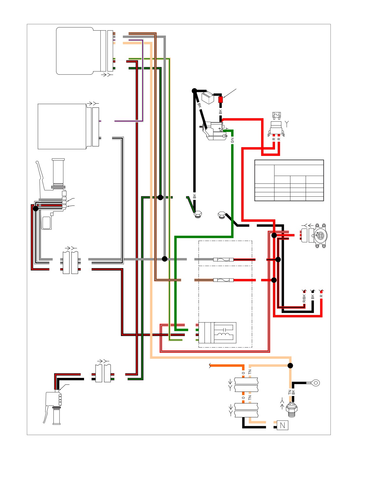
em01116
Battery
1
1
BN/GY
Ignition
2
2
GY
Serial data link
3
3
LGN/V
Neutral switch
4
4
TN
TSM/
TSSM/
HFSM
Start relay control
9
9
TN/GN
Clutch switch
10
10
BK/R
Ground
12
12
BK/GN
[30A] [30B]
Red
Battery
Band
Electronic
Control
[78A]
[78B]
Starting System
Module (ECM)
40A
MAXIFUSE
Serial data link
69
69
LGN/V
[
128A]
[128B]
[5B]
B A
Engine stop switch
72
72
W/BK
Starter
IGNITION SWITCH LEGEND
Right Hand
“X” INDICATES CONTINUITY
Controls
BETWEEN LEAD WIRES
SWITCH
IN POSITION INDICATED
POSITION
RED/
RED/
RED
GRAY
BLACK
LOCK
X
OFF
X
Engine Stop
IGN
X
X
X
BK/GN
ACC
X
X
Switch
Starter Switch
Ignition
Switch
[33B] [33A]
Rear
Front
BK
GND2
GND1
(Clear)
(Dirty)
R/GY
C
A
R
B
B
R/BK
A
I
[22A] [22B]
[64-2B]
1F
Ignition - 15A
1E
GY
3
3
GY
GY
R/BK
W/BK
4
4
W/BK
BK/R
6
6
BK/R
[64-1B]
2D
Battery - 15A
2C
BN/GY
R
To ignition
Relay
R/GY
3H
30
3
GN
4G
87
5
Start
BK/R
4H
86
1
Relay
TN/GN
3G
85
2
[24A] [24B]
To instrument fuse
Front GND
Stud
BK/R
7
7
BK/R
(Dirty)
BK
8
8
BK/GN
[20A]
1
13
Clutch
Switch
[20B]
1
13
[GND1A]
B
A
[131]
[21A]
6
5
Neutral
Left Hand
[21B]
6
5
Switch
Controls
Neutral
(BK)
TN
BK
Figure 1-1. Starting Circuit (FLHR/C/S)
1-4 2008 Touring Diagnostics: Starting / Charging
///////////////////////////////////////