Harley Davidson Sportster Models 2009. Service Repair Manual - page 53
 

  Главная      Harley Davidson     Harley Davidson Sportster Models 2009. Service Repair Manual


Search            copyright infringement  


Content      ..     51      52      53      54     ..


Harley Davidson Sportster Models 2009. Service Repair Manual - page 53


ON

A

B

C

ON

ON

OFF

OFF

OFF

Key On

Key On

Key On

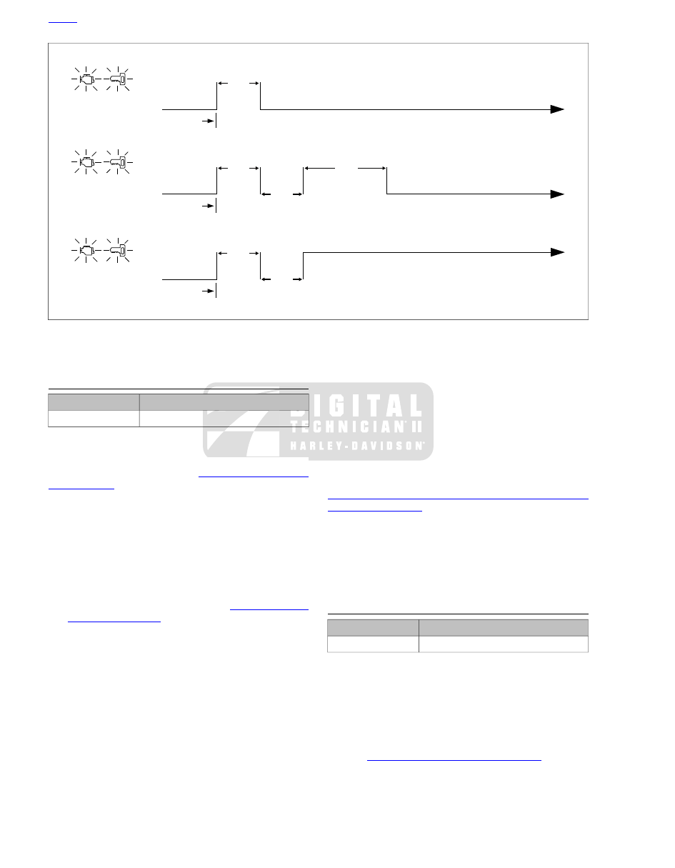
Lamp OFF: No Current or Historic DTCs

Lamp OFF

Lamp ON 8 Seconds:

Only Historic DTCs Exist

Lamp Remains ON: Current DTC*

* Historic DTCs May Also Exist

4 Sec.

4 Sec.

4 Sec.

4 Sec.

8 Sec.

4 Sec.

ed01046

Figure E-8. Security Lamp Operation

CODE TYPES

TOOL NAME

PART NUMBER

DIGITAL TECHNICIAN II

HD-48650

There are two types of DTCs: current and historic. If a DTC is
stored, it can be read using either a computer-based diagnostic
package called DIGITAL TECHNICIAN II (Part No. HD-48650)
or odometer self-diagnostics. See 

E.10 ODOMETER SELF-

DIAGNOSTICS

.

NOTES

Odometer self-diagnostics will display both current and
historic DTCs. To differentiate between current and historic
DTCs, a computer-based diagnostic package called
DIGITAL TECHNICIAN II (Part No. HD-48650) must be
employed.

All DTCs reside in the memory of the ECM, TSM/TSSM,
odometer or tachometer until the DTC is cleared by use
of the odometer self-diagnostics. See 

E.10 ODOMETER

SELF-DIAGNOSTICS

.

A historic DTC is also cleared after a total of 50 ignition
cycles has elapsed. After the 50 ignition cycles retention
period, the DTC is automatically erased from memory
providing that no subsequent faults of the same type are
detected in that period.

Current

Current DTCs are those which are present during the current
ignition cycle. See the appropriate flowcharts for solutions.

Historic

If a particular problem happens to resolve itself, the active
status problem is dropped and it becomes a historic DTC rather

than a current DTC. For example, intermittent output shorts
can become typical historic DTCs.

Historic DTCs are stored for 50 ignition cycles after any DTC
was last set as current to assist in the diagnosis of intermittent
faults. On the 50th cycle, the DTC will clear itself. The security
lamp will only indicate the existence of only historic DTCs for
two ignition cycles.

It is important to note that historic DTCs will exist whenever
the system indicates the existence of a current fault. See

E.8 DIAGNOSTIC TROUBLE CODES (DTC), Multiple Dia-
gnostic Trouble Codes

 if multiple DTCs are found.

Diagnostic charts are designed for use with current DTCs and
as a result they frequently suggest part replacement. When
diagnosing an historic DTC the charts can be helpful but should
not lead to part replacement without verification the part is
faulty.

RETRIEVING DIAGNOSTIC TROUBLE
CODES

TOOL NAME

PART NUMBER

DIGITAL TECHNICIAN II

HD-48650

The TSM/TSSM supports two levels of diagnostics.

The most sophisticated mode employs a computer-based
diagnostic package called DIGITAL TECHNICIAN II (Part
No. HD-48650).

The second mode requires using odometer self-dia-
gnostics. Speedometer, tachometer (if equipped),
TSM/TSSM and ECM DTCs can be accessed and cleared.
See 

E.10 ODOMETER SELF-DIAGNOSTICS

.

HOME

E-16  2009 Sportster Diagnostics:  Appendix E TSM/TSSM (Japan/Korea)

MULTIPLE DIAGNOSTIC TROUBLE CODES

While it is possible for more than one fault to occur and set
more than one DTC, there are several conditions which may
result in one fault setting multiple DTCs:

Serial data DTCs (U1016, U1255, U1300 and U1301) may be
accompanied by other DTCs. Always correct the serial data
DTCs before resolving the other DTCs.

Refer to 

Table E-9

. This table gives most TSM/TSSM DTCs a

priority ranking.

Table E-9. TSM/TSSM Diagnostic Trouble Codes (DTC) and Fault Conditions

SOLUTION

FAULT CONDITION

DTC

RANKING

E.20 DTC U1300, U1301 OR BUS ER

.

J1850 short-to-ground

U1300

1

E.20 DTC U1300, U1301 OR BUS ER

.

J1850 short-to-battery

U1301

2

E.19 DTC U1016, U1255

.

Loss of serial communications - ECM

U1016

3

E.19 DTC U1016, U1255

.

Loss of serial communication - general

U1255

4

E.17 DTC B1135

.

Accelerometer fault

B1135

5

E.18 DTC B1154, B1155

.

Clutch switch input short-to-ground

B1154

6

E.18 DTC B1154, B1155

.

Neutral switch input short-to-ground

B1155

7

E.16 DTC B1134

.

Start relay output short-to-ground

B1134

8

E.13 TURN SIGNAL ERRORS: B1121, B1122, B1141

.

Left turn lamp output fault

B1121

9

E.13 TURN SIGNAL ERRORS: B1121, B1122, B1141

.

Right turn lamp output fault

B1122

10

E.14 DTC B0563

.

Battery voltage high

B0563

11

E.15 DTC B1131, B1132

.

Alarm output short-to-ground

B1131

12

E.15 DTC B1131, B1132

.

Alarm output short-to-ground

B1132

13

E.13 TURN SIGNAL ERRORS: B1121, B1122, B1141

.

Ignition switch input short-to-ground or open

B1141

14

HOME

2009 Sportster Diagnostics:  Appendix E TSM/TSSM (Japan/Korea)  E-17

E.9

INITIAL DIAGNOSTIC CHECK: TSM/TSSM

GENERAL

TOOL NAME

PART NUMBER

DIGITAL TECHNICIAN II

HD-48650

To locate faulty circuits or other system problems, follow the
diagnostic flowcharts. For a systematic approach, always begin
with 

E.9 INITIAL DIAGNOSTIC CHECK: TSM/TSSM, Initial

Diagnostics

. Read the general information and then work your

way through the flowchart box by box.

Diagnostic Notes

If a numbered circle appears adjacent to a flowchart box, then
more information is offered in the diagnostic notes. Many dia-
gnostic notes contain supplemental information, descriptions
of various diagnostic tools or references to other parts of the
manual where information on the location and removal of
components may be obtained.

Circuit Diagram/Wire Harness Connector
Table

When working through a flowchart, refer to the illustrations,
the associated circuit diagram and the wire harness connector
table as necessary. The wire harness connector table for each
circuit diagram identifies the connector number, description,
type and general location.

In order to perform most diagnostic routines, a Breakout Box
and a digital volt/ohmmeter (DVOM) are required. See

E.11 BREAKOUT BOX: TSM/TSSM

.

To perform the circuit checks with any degree of efficiency, a
familiarity with the various wire connectors is also necessary.

Job/Time Code Values

Some charts may contain warranty job/time codes. Dealership
technicians filing warranty claims should use the job/time code
values printed in bold text underneath the appropriate repair.

Reprogramming ECM

Diagnostic charts frequently suggest ECM replacement. In the
event an ECM needs to be replaced, it must be reprogrammed

using a computer-based diagnostic package called DIGITAL
TECHNICIAN II (Part No. HD-48650). See your dealer. Pass-
word learn procedure must also be performed. See

E.21 TSM/TSSM: PASSWORD LEARN

.

INITIAL DIAGNOSTICS

TOOL NAME

PART NUMBER

BREAKOUT BOX

HD-42682

INSTRUMENT HARNESS ADAPTERS

HD-46601

Diagnostic Tips

If odometer reads "BUS Er" with the Ignition Switch turned
to IGN (Engine Stop Switch at RUN with the engine off),
check data bus for an open or short to ground between
data link connector [91A] terminal 3 and ECM connector
[78B] terminal 5, TSSM connector [30B] terminal 3,
speedometer connector [39B] terminal 2 on XL, C on XR,
or tachometer (if equipped) connector [108B] terminal 2.

Check for an open diagnostic test terminal between data
link connector [91A] terminal 3 and TSM/TSSM connector
[30B] terminal 3. With Ignition Switch turned to IGN, serial
data bus voltage should be typically 0.6-0.8 Volt. The
range of acceptable voltage is 0-7.0 Volts.

To identify intermittents, wiggle vehicle harness while
performing steps in the Initial Diagnostic Check flowcharts.

Diagnostic Notes

Each reference number below correlates to a circled number
on the flowchart(s).

1.

Connect BREAKOUT BOX (Part No. HD-42682) between
wire harness connector [39B] on XL, or connector [108B]
on XR, and speedometer connector [39A] on XL, or
tachometer connector [108A] on XR, using INSTRUMENT
HARNESS ADAPTERS (Part No. HD-46601). See

2.2 INITIAL DIAGNOSTIC CHECK: ODOMETER

.

2.

Compare TSM/TSSM system behavior to symptoms in

Table E-10

.

All TSM/TSSM DTCs are listed in 

Table E-9

.

Table E-10. Symptoms That May Not Set Diagnostic Trouble Codes

SOLUTION

SYMPTOM

E.12 FAILS TO DISARM (TSSM ONLY)

.

Fails to disarm

E.13 TURN SIGNAL ERRORS: B1121, B1122, B1141

.

Turn signal will not cancel or cancels
erratically

E.13 TURN SIGNAL ERRORS: B1121, B1122, B1141

.

Turn signal flashes double normal rate, all
bulbs good

Other DTCs

See 

2.2 INITIAL DIAGNOSTIC CHECK: ODOMETER

 for any

DTCs related to the odometer.

See 

4.5 INITIAL DIAGNOSTIC CHECK: EFI

 for any DTCs

related to the ECM.

HOME

E-18  2009 Sportster Diagnostics:  Appendix E TSM/TSSM (Japan/Korea)

BK

BK

BK

BK

BK

BK

GY

GY

GY

O/W

O/W

O/W

O/W

O

O

O

O

R

BN/GY

BN/GY

BN/GY

BN/GY

BN/GY

BN/GY

LGN/V

LGN/V

LGN/V

LGN/V

LGN/V

LGN/V

LGN/V

R/BK

R/BK

R/GY

1 2

3

12

1 2

3

12

1 2

5

7

6

1 2

5

7

6

1 2

5 6 7

1 2

Ignition

Ser

ial

data

Batter

y

Accessor

y

Ground

Ignition

Ser

ial

data

Batter

y

Accessor

y

Ground

Batter

y

Ignition

Ser

ial

data

Ground

5 6 7

[39B]

[39A]

[108B]

[108A]

[30B]

[30A]

[91A]

Speedometer

TSM/TSSM

Tachometer (Optional)

12V ACCY

Fuse

12V BATT

Fuse

12V INSTR

Fuse

12V IGN

Fuse

3

2

1

4

Data Link

Connector

2

1

6

7

12

2

1

6

7

12

[20A]
[20B]

ECM

Ser

ial

data

[78A]

[78B]

5

5

To ACCY fuse

To BATT fuse

To INSTR fuse

To IGN fuse

[GND1]

[GND1]

[GND1]

em01182

Figure E-9. Diagnostic Check (XL)

HOME

2009 Sportster Diagnostics:  Appendix E TSM/TSSM (Japan/Korea)  E-19

BK

BK

BK

GY

GY

O/W

O/W

O/W

O/W

O

R

BN/GY

BN/GY

BN/GY

BN/GY

BN/GY

LGN/V

BK

BK

GY

BK

O/W

O

O

O

BN/GY

LGN/V

LGN/V

LGN/V

LGN/V

LGN/V

LGN/V

R/BK

R/BK

R/GY

1 2

3

12

1 2

3

12

1 2

5

7

6

1 2

5

7

6

C

B A D

C

B A D

Ser

ial

Data

Batter

y

Accessor

y

Ground

Ignition

Ser

ial

Data

Batter

y

Batter

y

Ignition

Ser

ial

Data

Ground

Accessor

y

Ground

Speedometer

TSM/TSSM/HFSM

Tachometer

To ACCY Fuse

To BATT Fuse

To INSTR Fuse

To IGN Fuse

12V ACCY

Fuse

12V BATT

Fuse

12V INSTR

Fuse

12V IGN

Fuse

3

1

2

4

Ground

Serial Data

Power

Data Link
Connector

2

1

6

7

12

2

1

6

7

12

ECM

Ser

ial

Data

5

5

GND1

GND1

GND1

[78B]

[78A]

[108A]

[108B]

[20A]

[20B]

[39A]

[39B]

[30A]

[30B]

[91A]

em01304

Figure E-10. Diagnostic Check (XR)

Table E-11. Wire Harness Connectors

LOCATION

TYPE

DESCRIPTION

NO.

Under fuel tank

12-place Molex

Instruments

[20]

Under battery tray

12-place Deutsch

TSM/TSSM

[30]

Back of speedometer

12-place Packard

Speedometer (XL)

[39]

Back of speedometer

5-place Packard

Speedometer (XR)

[39]

Under seat

36-place Packard

ECM

[78]

HOME

E-20  2009 Sportster Diagnostics:  Appendix E TSM/TSSM (Japan/Korea)

Table E-11. Wire Harness Connectors

LOCATION

TYPE

DESCRIPTION

NO.

Under left side cover

4-place Deutsch

Data link connector

[91]

Back of tachometer

12-place Packard

Tachometer (if equipped)

[108]

HOME

2009 Sportster Diagnostics:  Appendix E TSM/TSSM (Japan/Korea)  E-21

Initial Diagnostic Check (Part 1 of 3)

Does Engine

start?

YES.

Starts and runs.

YES.

Starts, then stalls.

NO.

Cranks, but will not start.

NO.

Engine will not crank.

Check for DTCs. See E.10

ODOMETER

SELF-DIAGNOSTICS.

DTCs found?

See 4.11 STARTS,

THEN STALLS.

See 4.9 ENGINE CRANKS,

BUT WILL NOT START.

See 1.2 STARTING

SYSTEM DIAGNOSIS.

YES

Refer to applicable DTC priority

chart. All DTCs are listed in Table

E-9. DTCs are listed by priority.

NO

Unable to enter

diagnostic mode.

NO

No DTCs

displayed.

With ignition switch OFF, press and

release trip odometer reset switch.

Does odometer display appear with

backlighting?

For a list of symptoms that
may not set DTCs, refer to

Table E-10.

YES

NO

Check for continuity to ground at

Breakout Box terminal 7 (Black). Wiggle

harness during continuity check.

Is continuity present?

YES

NO

Check for battery voltage at Breakout Box

terminal 5 (Black) while wiggling harness.

Is battery voltage continuously present?

Locate and

repair open

between

terminal 7

and ground.

YES

NO

With ignition switch OFF and speedometer

connector [39] on XL or tachometer connector [108]

on XR disconnected, check continuity

between Breakout Box terminals 8 and 11 (Black).

Is continuity present when trip odometer reset

switch is depressed and infinity when released?

Locate and

repair open

between

terminal 5

and

battery fuse.

YES

NO

Replace

speedometer (XL),

tachometer (XR).

Replace trip odometer

reset switch.

1

2

fc01997_en

Go to Initial Diagnostic

Check (Part 2 of 3).

HOME

E-22  2009 Sportster Diagnostics:  Appendix E TSM/TSSM (Japan/Korea)

Initial Diagnostic Check (Part 2 of 3)

Continued from Initial Diagnostic Check (Part 1 of 3).

Turn ignition switch ON.

Is odometer backlight present?

YES

NO

Replace speedometer (XL),

tachometer (XR).

Perform “WOW” test.

See E.10 ODOMETER SELF-DIAGNOSTICS.

The following features should be functional

1) backlight should illuminate
2) needle should sweep its full range of motion
3) LED’s should illuminate:

• check engine
• battery

• security (all models)

4) LED’s that may illuminate:

• low fuel
• cruise (although not cruise equipped)

Are all features functional?

YES

Turn ignition switch to ACC.

Is backlight present?

YES

NO

Check for battery voltage at

Breakout Box terminal 6 (Black).

Is battery voltage present?

YES

NO

Replace

speedometer (XL),

tachometer (XR).

Is accessory

fuse good?

YES

Locate and repair

source of fault.

Replace fuse.

Locate and repair open
on (O/W) wire between

terminal 6 of connector

[39] on XL, or connector

[108] on XR and

accessory fuse.

1

NO

With ignition switch turned to IGNITION, check for

battery voltage at terminal 1 of Breakout Box.

Is battery voltage present?

YES

NO

Replace speedometer (XL),

tachometer (XR).

Is instrument

fuse good?

YES

NO

Locate and

repair

source of fault.

Replace fuse.

Locate and repair open

between terminal 1 of

connector [39] on XL, or

connector [108] on XR

and

instrument fuse.

1

fc02007_en

NO

Go to Initial

Diagnostic

Check (Part 3 of

3).

HOME

2009 Sportster Diagnostics:  Appendix E TSM/TSSM (Japan/Korea)  E-23

Initial Diagnostic Check (Part 3 of 3)

Continued from Initial Diagnostic Check (Part 2 of 3).

Is problem intermittent?

YES

Repeat Initial Diagnostic

Check while wiggling

harnesses.

Is intermittent present?

YES

NO

Locate and

repair

intermittent.

No trouble

found.

NO

Speedometer inoperative

(no vehicle speed).

Remove and inspect

VSS.

Is debris present?

YES

Remove debris.

Reinstall VSS.

NO

Check for damaged wiring/loose

connection between VSS and

ECM.

Is wiring damage/ loose

connection present?

YES

NO

Locate and repair

source of fault.

Replace

speedometer.

NO

Tachometer Inoperative

(no engine speed).

See 2.4 SPEEDOMETER/

TACHOMETER.

2

fc01960_en

XL

XR

Go to

Speedometer

Inoperative

(XR).

HOME

E-24  2009 Sportster Diagnostics:  Appendix E TSM/TSSM (Japan/Korea)

Speedometer Inoperative (XR)

All features should be functional on the

tachometer.

Are all features functional?

YES

NO

YES

NO

Is battery fuse

good?

YES

NO

Locate and repair

source of fault.

Replace fuse.

Locate and repair

open in (BN/GY) wire

between terminal B of

connector [39B] and

connector [20A] main

harness.

Check for continuity

between Breakout Box

terminal 2 and terminal C

of connector [108B].

Is continuity present?

YES

NO

Locate and

repair open
on (LGN/V)

wire.

fc01931_en

Does backlight

illuminate?

Check for battery voltage at

connector [39B] terminal B.

Is battery voltage present?

NO

YES

1

With ignition ON, Check

for voltage at connector

[39B] terminal A.

Is battery voltage

present?

NO

Is accessory

fuse good?

Locate and repair

source of fault.

Replace fuse.

YES

Check for continuity between Breakout Box

terminal 7 and terminal D of connector

[108B].

Is continuity present?

YES

Locate and

repair open

on (BK) wire.

NO

YES

Locate and repair

source of fault.

Replace fuse.

NO

Replace

speedometer.

Remove and inspect

VSS.

Is debris present?

YES

Remove debris.

Reinstall VSS.

YES

Locate and repair

source of fault.

Check for damaged wiring/

loose connection between

VSS and ECM.

Is wiring damage/loose

connection present?

NO

NO

Replace

speedometer.

Go to Initial

Diagnostic Check

(Part 1 of 3).

HOME

2009 Sportster Diagnostics:  Appendix E TSM/TSSM (Japan/Korea)  E-25

E.10

ODOMETER SELF-DIAGNOSTICS

GENERAL

The odometer is capable of displaying and clearing speedo-
meter, tachometer, TSM/TSSM, ABS, and ECM DTCs (dia-
gnostic mode).

DIAGNOSTICS

Diagnostic Tips

For a quick check of speedometer (XL) or tachometer (XR)
functions, a "WOW" test can be performed. Press and
hold trip odometer reset switch then turn ignition switch
ON. Release trip odometer reset switch. See 

Figure E-11

.

Background lighting should illuminate, gauge needles
should sweep their full range of motion, and indicator
lamps (battery, security, low fuel, and check engine) should
illuminate. All lamps should illuminate, even those not
used in normal vehicle operations.

If speedometer (XL) or tachometer (XR) fails "WOW" test,
check for battery, ground, ignition, trip odometer reset
switch and accessory wiring to speedometer. If any feature
in the speedometer is non-functional, see 

2.2 INITIAL

DIAGNOSTIC CHECK: ODOMETER

.

Diagnostic Notes

Each reference number below correlates to a circled number
on the flowchart(s).

1.

To exit diagnostic mode, turn ignition switch OFF.

2.

To clear DTCs for the selected module, press the trip
odometer reset switch for more than 5 seconds when a
DTC is displayed. This procedure will clear all DTCs for
the selected module.

1

2

3

4

5

ed01721

1.

Sixth gear indicator (not used)

2.

Check engine lamp

3.

Low fuel lamp

4.

Battery lamp

5.

Security lamp (key icon)

Figure E-11. Warning Lamps (Typical)

OFF

ACC.

IGNITION

3

1

2

ed02814

1.

Ignition OFF

2.

Accessory (ACC) ON

3.

Ignition ON

Figure E-12. Ignition Switch

HOME

E-26  2009 Sportster Diagnostics:  Appendix E TSM/TSSM (Japan/Korea)

Odometer Self-Diagnostics

1

While holding trip odometer reset

switch in, turn ignition switch to

IGNITION.

Make sure engine stop switch is in

RUN position.

Release trip odometer

reset switch.

Does “diag” appear?

YES

”P” flashing.

To display DTCs for the

ECM, press and hold trip

odometer reset switch for more

than 5 seconds.

To display DTCs for

TSM/TSSM, press and hold trip

odometer reset switch for more

than 5 seconds.

To choose TSM/

TSSM/HFSM, press

and release trip odometer

reset switch.

”S” flashing.

To choose speedometer,

press and release trip

odometer reset switch.

”SP” flashing.

To choose tachometer,

press and release trip odometer

reset switch.

To choose ABS, press

and release trip odometer

reset switch.

”T” flashing.

To display DTCs for

speedometer, press and

hold trip odometer reset

switch for more than 5

seconds.

To display DTCs for tachometer,

press and hold trip odometer

reset switch for more than 5

seconds.

Press and release trip

odometer reset switch again to

continue to next module.

See 2.2 INITIAL

DIAGNOSTIC

CHECK: ODOMETER.

YES

YES

NO

NO

NO

Device

response?

Press and release

trip odometer reset

switch. Part number

of module will be

displayed.

Press and release trip

odometer reset switch.

Are more DTCs displayed?

“end” displayed. To clear all DTCs for selected

module hold trip odometer reset switch for more than

5 seconds. If DTCs are not to be cleared, Press and

release trip odometer reset switch. Part number of

module will be displayed.

“no rsp” displayed. See applicable code from

other modules. Models not equipped with a

tachometer or ABS will display “no rsp” normally.

If “no rsp” displayed on odometer on tachometer

equipped vehicle, See 2.4 SPEEDOMETER/

TACHOMETER.

“none” displayed.

DTC

displayed.

Press and release trip odometer reset switch.

“PSSPtb” appears.

2

”b” flashing.

To display DTCs for

ABS, press and

hold trip odometer reset

switch for more

than 5 seconds.

To choose ECM, press

and release trip odometer

reset switch.

fc01815_en

HOME

2009 Sportster Diagnostics:  Appendix E TSM/TSSM (Japan/Korea)  E-27

E.11

BREAKOUT BOX: TSM/TSSM

GENERAL

TOOL NAME

PART NUMBER

BREAKOUT BOX

HD-42682

The BREAKOUT BOX (Part No. HD-42682) splices into the
main harness. Used in conjunction with a DVOM, it allows cir-
cuit diagnosis of wiring harness and connections without having
to probe with sharp objects.

INSTALLATION

TOOL NAME

PART NUMBER

BREAKOUT BOX

HD-42682

1.

Remove left side cover and battery. See the service
manual.

2.

See 

Figure E-13

. Reach under battery tray and lift

TSM/TSSM from cavity in bottom of tray.

3.

See 

Figure E-14

. Depress latches on harness connector

[30B] and remove from TSM/TSSM connector [30A].

4.

Route harness connector [30B] back down through cavity
and out left side of vehicle under battery tray.

5.

Reinstall battery.

6.

See 

Figure E-15

. Attach BREAKOUT BOX (Part No. HD-

42682) to connectors:

a.

Mate gray socket housing on BREAKOUT BOX (Part
No. HD-42682) with TSM/TSSM connector [30A].

b.

Mate gray pin housing on BREAKOUT BOX (Part
No. HD-42682)with harness connector [30B].

ed02825

Figure E-13. TSM/TSSM Location

1

2

3

ed02818

1.

Harness connector

2.

Pin 1

3.

Pin 12

Figure E-14. TSM/TSSM Connector [30A]

2

3

1

ed02832

1.

TSM/TSSM

2.

Tester harness connectors

3.

Vehicle's TSM/TSSM harness connector [30B]

Figure E-15. Breakout Box: TSM/TSSM

HOME

E-28  2009 Sportster Diagnostics:  Appendix E TSM/TSSM (Japan/Korea)

REMOVAL

TOOL NAME

PART NUMBER

BREAKOUT BOX

HD-42682

1.

Disconnect BREAKOUT BOX (Part No. HD-42682) from
vehicle:

a.

See 

Figure E-14

. Depress latches and detach gray

BREAKOUT BOX (Part No. HD-42682) socket con-
nector from TSM/TSSM connector [30A] (1).

b.

See 

Figure E-15

. Detach gray BREAKOUT BOX (Part

No. HD-42682) pin connector from harness connector
[30B] (3).

2.

Remove battery. Route TSM/TSSM harness connector
[30B] up through cavity in bottom of battery tray.

3.

Mate harness connector [30B] to TSM/TSSM.

4.

Position TSM/TSSM with connector facing toward rear of
vehicle. Lower TSM/TSSM down into cavity in bottom of
battery tray.

5.

Install battery, MAXIFUSE, and left side cover. See the
service manual.

NOTE

Vehicle will not start with TSM/TSSM disconnected or incor-
rectly mounted.

Table E-12. TSM/TSSM Connector [30B]

FUNCTION

TERMINAL

FUNCTION

TERMINAL

Right turn switch input

7

Battery

1

Left turn switch input

8

Ignition

2

Start relay control

9

Serial data

3

Clutch switch

10

Neutral switch

4

Alarm signal

11

Left turn feed

5

Ground

12

Right turn feed

6

HOME

2009 Sportster Diagnostics:  Appendix E TSM/TSSM (Japan/Korea)  E-29

E.12

FAILS TO DISARM (TSSM ONLY)

GENERAL

Security Equipped Vehicles Only

This section applies only to those vehicles equipped with the
optional TSSM.

NOTE

Disarming function may require practice. The key fob button
must be pressed twice within 1.5 seconds to send the disarm
command. The action is very similar to double-clicking a com-
puter mouse. Light quick taps work best; very hard or very slow
taps are less likely to work.

The key fob sends a RF signal to activate all remote TSSM
functions. The left front turn signal switch wire serves as the
vehicle's antenna. If the TSSM does not respond (no confirm-
ation at arming/disarming system) or responds weakly (limited
range, won't consistently arm/disarm or synchronize), follow
the flowchart.

Job/Time Code Values

Dealership technicians filing warranty claims should use the
job/time code values printed in bold text underneath the
appropriate repair.

ed03009

Figure E-16. Key Fob Battery: TSSM

DIAGNOSTICS

Diagnostic Tips

Verify key fob battery voltage is at least 2.9 volts. See

E.22 TSSM MAINTENANCE

.

Interference from physical surroundings may affect RF
transmission. Place fob next to left handgrip and disarm
with two clicks or move motorcycle to a new location and
retest.

Check for damage to antenna wire. Does left turn signal
work?

NOTE

See 

E.7 ARMING/DISARMING (TSSM ONLY)

. Use only the

proper key fob for your market and TSSM package.

Diagnostic Notes

Each reference number below correlates to a circled number
on the flowchart(s).

1.

After a battery disconnect, the TSSM will not enter the
configuration mode on the first attempt. All attempts to
assign a fob or enter the configuration mode will require
at least two attempts.

HOME

E-30  2009 Sportster Diagnostics:  Appendix E TSM/TSSM (Japan/Korea)

1

8

12

1

8

12

5

5

Left Turn Signal

Switch

Engine Case

Ground Point

GND 1

Battery

15 Amp

Battery

Fuse

To Ignition

Switch

TSM/TSSM

30 Amp

MAXIFUSE

Key Fob Antenna

(TSSM Only)

Batter

y

Ground

Left

T

ur

n

Switch

Input

[30B]

[30A]

[24A]

[24B]

BN/GY

BN/GY

BK

BK

W/V

W/V

W/V

W/V

R

R

R

R

R

em00259

Figure E-17. Antenna Circuit

Table E-13. Wire Harness Connectors

LOCATION

TYPE

DESCRIPTION

NO.

Under fuel tank

8-place Molex

Left hand controls and horn

[24]

Under battery

12-place Deutsch

TSM/TSSM

[30]

HOME

2009 Sportster Diagnostics:  Appendix E TSM/TSSM (Japan/Korea)  E-31


Content      ..     51      52      53      54     ..