Harley Davidson 2011 Touring Models. Service Manual - page 45
 

  Главная      Harley Davidson     Harley Davidson 2011 Touring Models. Service Manual


Search            copyright infringement  


Content      ..     43      44      45      46     ..


Harley Davidson 2011 Touring Models. Service Manual - page 45


A.12

DEUTSCH DT SEALED CONNECTORS

DEUTSCH DT SEALED CONNECTOR
REPAIR

TOOL NAME

PART NUMBER

DEUTSCH TERMINAL REPAIR KIT

HD-41475

FLAT BLADE L-HOOK

HD-41475-100

General

Deutsch DT Sealed connectors are colored coded for location
purposes. Those connectors associated with

left

side

accessories, such as the front and rear

left

turn signals, are

gray

. All other connectors, including those associated with

right side accessories, are

black

.

NOTE

A DEUTSCH TERMINAL REPAIR KIT (Part No. HD-41475)
contains a selection of wire seals, internal seals, seal plugs,
secondary locking wedges, attachment clips and socket/pin
terminals. Also included is a compartmented storage box,
carrying case and a FLAT BLADE L-HOOK (Part No. HD-
41475-100) is used for the removal of all types of locking
wedges.

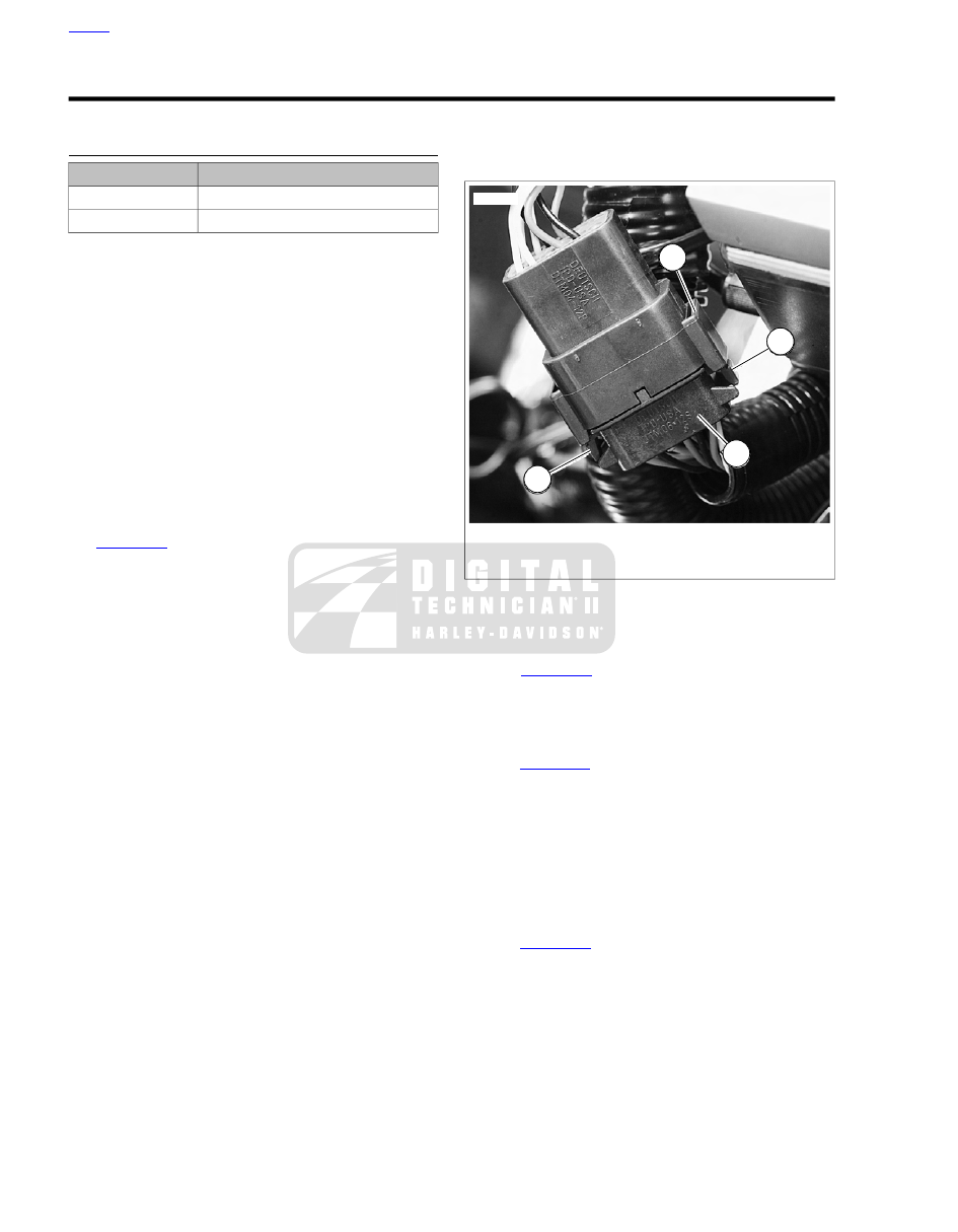
Separating Pin and Socket Housings

See

Figure A-26

To separate the connector halves, Press the

external latch(es) (1) on the socket housing (2) while rocking
the pin (3) and socket housings.

NOTES

Generally, the socket housing is found on the accessory
side, while the pin housing is plumbed to the wiring har-
ness.

Two-, three-, four- and six-place Deutsch connectors have
one latch on the connector.

Eight- and twelve-place connectors have a latch on each
side. Simultaneously press both latches to separate the
connector.

Mating Pin and Socket Housings

1.

Align the connectors to match the wire lead colors.

a.

For One External Latch:

Two-, three-, four- and six-

place Deutsch connectors have one external latch on
the socket half of the connector. To fit the halves of
the connector together, the latch on the socket side
must be aligned with the latch cover on the pin side.

b.

For Two External Latches:

(8-place and 12-place)

Align the tabs on the socket housing with the grooves
on the pin housing.

2.

Insert socket housing into pin housing until it snaps or
clicks into place.

For Two External Latches:

(8-place and 12-place) If

latches do not click (latch), press on one side of the con-
nector until that latch engages, then press on the opposite
side to engage the other latch.

3.

If necessary, fit the attachment clip to the pin housing.

4.

Place large end of slot on attachment clip over T-stud on
frame. Push assembly forward to engage small end of
slot.

2

3

1

1

sm00017

1. External latch
2. Socket housing
3. Pin housing

Figure A-26. Deutsch DT Sealted Connector

Removing Socket Terminals

1.

See

Figure A-27

. Insert a small screwdriver between the

socket housing and locking wedge in-line with the groove
(in-line with the pin holes if the groove is absent). Turn the
screwdriver 90 degrees to pop the wedge up and remove
the secondary locking wedge.

2.

See

Figure A-30

. Use a pick or small screwdriver to Press

terminal latches inside socket housing and back out
sockets through holes in rear wire seal.

NOTE

If wire leads require new terminals, see the instructions for
crimping terminals.

Installing Socket Terminals

1.

Match wire lead color to connector cavity.

2.

See

Figure A-29

. Fit rear wire seal (1) into back of socket

housing (2), if removed.

3.

Grasp wire lead (3) approximately 1.0 in. (25.4 mm) behind
the socket terminal. Gently push socket through hole in
wire seal into its chambers until it "clicks" in place.

4.

A tug on the wire will confirm that it is properly locked in
place.

HOME

A-20 2011 Touring Service: Appendix A Connector Repair

NOTE

Seal plugs (6) are installed through the wire seals of unused
chambers. If removed, seal plugs must be replaced to seal the
connector.

5.

Install internal seal (4) on lip of socket housing, if removed.

6.

Insert tapered end of secondary locking wedge (5) into
socket housing and press down until it snaps in place. The
wedge fits into the center groove within the socket housing
and holds the terminal latches tightly closed.

NOTES

See

Figure A-28

. While rectangular wedges do not require

a special orientation, the conical secondary locking wedge
of the 3-place connector must be installed with the arrow
(1) pointing toward the external latch.

If the secondary locking wedge does not slide into the
installed position easily, verify that all terminals are fully
installed in the socket housing. The lock indicates when
terminals are not properly installed by not entering its fully
installed position.

sm00009

Figure A-27. Deutsch DT Sealed Connector: Remove

Secondary Locking Wedge

2

1

sm00018

1. Arrow on socket locking wedge
2. Arrow on pin locking wedge

Figure A-28. Deutsch DT Sealed Connector: 3-Place

Locking Wedges

HOME

2011 Touring Service: Appendix A Connector Repair A-21

DEUTSCH

6

1

2

3

4

5

sm00010

1. Wire seal
2. Socket housing
3. Wire lead
4. Internal seal
5. Secondary locking wedge
6. Seal plug

Figure A-29. Deutsch DT Sealed Connector: 2, 3, 4 and

12-Place Socket Housings

Removing Pin Terminals

1.

Use the hooked end of a stiff piece of mechanics wire, a
needle nose pliers or the FLAT BLADE L-HOOK (Part
No. HD-41475-100) to remove the secondary locking
wedge.

2.

Gently Press terminal latches inside pin housing and back
out pins through holes in wire seal.

NOTES

If wire leads require new terminals, see the instructions
for crimping terminals.

If it should become necessary to replace a pin or socket
housing, note that the 8-place and 12-place gray and black
connectors are not interchangeable. Since location of the

alignment tabs differ between the black and gray con-
nectors, plugs or receptacles must be replaced by those
of the same color.

When replacing both socket and pin housings, then the
black may be substituted for the gray. The socket and pin
housings of all other connectors are interchangeable, that
is, the black may be mated with the gray, since the align-
ment tabs are absent and the orientation of the external
latch is the same.

sm00019

Figure A-30. Deutsch DT Sealed Connector: Depress

Terminal Latch and Back Out Pin

Installing Pin Terminals

1.

See

Figure A-31

Fit wire seal (1) into back of pin housing

(2).

2.

Grasp wire lead approximately 1.0 in. (25.4 mm) behind
the pin terminal (3). Gently push pin through holes in wire
seal into its respective numbered chamber until it "clicks"
in place.

NOTE

A tug on the wire lead will confirm that a pin is locked in place.

3.

Insert tapered end of secondary locking wedge (4) into
pin housing and press down until it snaps in place.

NOTES

The wedge fits in the center groove of the pin housing and
holds the terminal latches tightly closed.

See

Figure A-28

. While rectangular wedges do not require

a special orientation, the conical secondary locking wedge
of the 3-place connector must be installed with the arrow
(2) pointing toward the external latch.

If the secondary locking wedge does not slide into the
installed position easily, verify that all terminals are fully
installed in the pin housing. The lock indicates when ter-
minals are not properly installed by not entering its fully
installed position.

HOME

A-22 2011 Touring Service: Appendix A Connector Repair

DEUTSCH

1

2

3

4

sm00020

1. Wire seal
2. Pin housing
3. Pin terminal
4. Locking wedge

Figure A-31. Deutsch DT Sealed Connector: 2, 3, 4 and

12-Place Pin Housings

Crimping Terminals

Identify which of the types of Deutsch terminals are used with
the connector and follow the corresponding crimping instruc-
tions. Refer to

Table A-1

.

Table A-1. Deutsch Connector: Terminal Crimping Instructions

CRIMPING INSTRUCTIONS

TYPE

A.13 DEUTSCH DT SEALED TERMINAL REPAIR

DT Sealed (with crimp tails)

A.15 DEUTSCH DTM SEALED SOLID BARREL MINI TERMINAL REPAIR

DTM Mini Sealed Terminal (solid
barrel)

A.14 DEUTSCH DTM SEALED MINI TERMINAL REPAIR

DTM Mini Sealed Terminal (with crimp
tails)

HOME

2011 Touring Service: Appendix A Connector Repair A-23

A.13

DEUTSCH DT SEALED TERMINAL REPAIR

DEUTSCH DT SEALED TERMINAL CRIMPS

TOOL NAME

PART NUMBER

DEUTSCH TERMINAL CRIMP TOOL

HD-39965-A

Preparing Wire Leads for Crimping

1.

Use a shop gauge to determine gauge of wire lead.

2.

Strip lead removing 5/32 in. (4.0 mm) of insulation.

Crimping Terminal to Lead

1.

See

Figure A-32

. Squeeze the handles of the DEUTSCH

TERMINAL CRIMP TOOL (Part No. HD-39965-A) to open
the jaws. Push the locking bar (1) up.

2.

Insert (2) terminal (socket/pin) through hole of the locking
bar, so that the rounded side of the contact barrel rests in
the nest (concave split level area) with the crimp tails
facing upward. To match the wire gauge to the crimp tool
die, refer to

Table A-2

.

3.

Release locking bar to lock terminal in die.

NOTE

If the crimp tails are slightly out of vertical alignment, the crimp
tool automatically rotates the terminal so that the tails face

straight upward. When positioned, the locking bar fits snugly
in the space between the contact band and the core crimp tails.

4.

Insert stripped wire core between crimp tails until ends
make contact with locking bar. Verify that wire is positioned
so that short pair of crimp tails squeeze bare wire strands,
while long pair folds over the insulation.

5.

Squeeze handle of crimp tool until tightly closed. Tool
automatically opens after the terminal is crimped.

6.

Raise locking bar up and remove wire lead and terminal.

Inspecting Crimps

Inspect the wire core and insulation crimps. Distortion should
be minimal.

Table A-2. Deutsch DT Sealed Terminal Crimp: Wire Gauge

To Die

CRIMP TOOL DIE

WIRE GAUGE (AWG)

Front

20

Middle

16-18

2

5

4

6

1

3

sm00021

4.

1.

Insert stripped lead

Open jaws and raise locking bar

2.

5.

Insert terminal in locking bar

Squeeze crimper

6.

3.

Raise locking bar and remove terminal

Release locking bar to lock terminal in die

Figure A-32. Crimping a Deutsch DT Sealed Terminal

HOME

A-24 2011 Touring Service: Appendix A Connector Repair

A.14

DEUTSCH DTM SEALED MINI TERMINAL
REPAIR

DEUTSCH DTM SEALED MINI TERMINAL
CRIMPS

TOOL NAME

PART NUMBER

PACKARD TERMINAL CRIMPER

HD-38125-7

Preparing Wire Leads for Crimping

Strip wire lead removing 5/32 in. (4.0 mm) of insulation.

Crimping a Mini Terminal to Wire Lead

1.

See

Figure A-33

Compress the handles of PACKARD

TERMINAL CRIMPER (Part No. HD-38125-7) until the
ratchet (2) automatically opens.

NOTE

Always perform core crimp before insulation crimp.

2.

Position the core crimp on die E (1) of the crimper. Be
sure the core crimp tails are facing the forming jaws.

3.

Gently apply pressure to handles of tool until crimpers just
secure the core crimp tails.

4.

Insert stripped wire core stands between crimp tails. Pos-
ition wire so that short pair of crimp tails squeeze bare
wire strands, while long pair squeeze over the insulation.

5.

Squeeze handle of crimper until tightly closed. Tool auto-
matically opens when the crimping sequence is complete.

NOTE

If the crimper does not open, it can be opened by squeezing
the ratchet trigger (2).

6.

Position the insulation crimp on nest C of the crimper. Be
sure the insulation crimp tails are facing the forming jaws.

7.

Squeeze handle of crimp tool until tightly closed. Tool
automatically opens when the crimping sequence is com-
plete.

Inspecting Crimps

Inspect the core and insulation crimps. Distortion should be
minimal.

2

1

sm00022

1. E die
2. Crimper ratchet trigger

Figure A-33. Packard Terminal Crimper (HD-38125-7)

HOME

2011 Touring Service: Appendix A Connector Repair A-25

A.15

DEUTSCH DTM SEALED SOLID BARREL MINI
TERMINAL REPAIR

DEUTSCH DTM SEALED SOLID BARREL
TERMINAL CRIMPS

TOOL NAME

PART NUMBER

ELECTRICAL CRIMPER TOOL

HD-42879

Preparing Wire Leads For Crimping

For size 20, 16 and 12 contacts, wire ranges 26-12 AWG.

Strip wire lead removing 1/4 in. (6.4 mm) of insulation.

Adjusting Crimper Tool

1.

See

Figure A-34

Squeeze the ELECTRICAL CRIMPER

TOOL (Part No. HD-42879) handles to cycle the crimp
tool to open.

2.

Remove locking pin (1) from selector knob (2).

3.

Raise selector knob and rotate until selected wire size
stamped on wheel is aligned with "SEL. NO." arrow (3).

4.

Loosen knurled locknut (4) and turn adjusting screw (5)
clockwise (in) until it stops.

Crimping a Barrel Contact To Wire Lead

1.

See

Figure A-35

. Turn tool over and drop contact barrel

(1) into indentor cover (2) hole with the wire end out.

2.

Turn adjusting screw counterclockwise (out) until contact
is flush with bottom of depression in indentor cover.
Tighten knurled locknut.

3.

Slowly squeeze handles of crimp tool until contact is
centered between the four indentor points (3).

4.

Insert bare wire core strands of stripped wire lead (4) into
contact barrel. Squeeze handle of crimp tool until tightly
closed. Tool automatically opens when the crimping
sequence is complete.

5.

Remove wire lead with crimped contact from indentor.

NOTE

Tool must be readjusted when changing contact size/type.

6.

Install pin to lock selector knob.

Inspecting Crimps

Inspect the crimp. All core wire strands are to be crimped in
the barrel.

This

HAND

tool

m

ust

not

be

used

in

an

y

po

w

ered

"PRESS''

as

defined

b

y

OSHA

CFR

1910.211

(46)

2

4

5

1

3

sm00023

1. Locking pin
2. Selector knob
3. SEL. NO. arrow
4. Knurled locknut
5. Adjusting screw

Figure A-34. Electrical Crimper Tool (HD-42879)

HOME

A-26 2011 Touring Service: Appendix A Connector Repair

HDT

- 48

- 00

JDG360-1

HEMET

RYAN

AIRPOR

T, P

.O

. BO

X 878

HEMET

, CA.

92343-0161

(714)

929-1200

INDUSTRIAL

PRODUCTS

DIVISION

HDT

- 48

- 00

JDG360-1

HEMET

RYAN

AIRPOR

T, P

.O

. BO

X 878

HEMET

, CA.

92343-0161

(714)

929-1200

INDUSTRIAL

PRODUCTS

DIVISION

2

1

3

4

3

sm00024

1. Contact barrel
2. Indentor cover
3. Indentor point
4. Stripped wire lead

Figure A-35. Deutsch Solid Barrel

HOME

2011 Touring Service: Appendix A Connector Repair A-27

A.16

JAE MX19 SEALED CONNECTORS

JAE MX19 SEALED CONNECTORS

TOOL NAME

PART NUMBER

TERMINAL EXTRACTOR

B-50085

Connector Housings

Separate Housings:

See

Figure A-36

Press the two release

buttons on each side of the housing to separate the connector.

Connect Housings:

Align and press the housings together

until the locking tabs click.

sm06925

Figure A-36. Release Buttons: JAE MX19 Sealed Connector

Removing Terminals

1.

Modify a TERMINAL EXTRACTOR (Part No. B-50085) by
filing the front edge to 45 degrees.

2.

See

Figure A-37

Insert the extractor (1) into the opening

above the terminal and press the plastic molding (2) up
and out of the way.

3.

Pull the wire lead and terminal out of the back of the
housing.

Installing Terminals

1.

Inspect the plastic molding and replace the connector
housing if necessary.

2.

Orient the terminal to the housing and push terminal into
the housing until it snaps into place.

1

2

2

1

sm06926

1. Extractor tool
2. Molding

Figure A-37. JAE MX19 Terminal Removal

HOME

A-28 2011 Touring Service: Appendix A Connector Repair

A.17

MOLEX CMC SEALED CONNECTORS

MOLEX CMC SEALED CONNECTORS

Separating the Connector

Release:

See

Figure A-38

Press the catch and rotate the lever

arm down.

Connect:

Press on the front guard to release the latch and

rotate the lever arm up until the catch clicks in place.

sm06931

Figure A-38. Release

Removing Terminals

1.

With the lever arm open, cut the cable strap around the
wire bundle.

2.

See

Figure A-39

. Open a wire cap latch with a small

screwdriver (1).

3.

Maintain pressure on the cap and open the opposite latch
with the screw driver (2).

4.

Slide the cap off (3).

5.

See

Figure A-40

. Use the screwdriver to open the sec-

ondary lock. Pull the locking bar all the way out.

6.

See

Figure A-41

Locate the wire lead cavity by the alpha-

numeric coordinates.

7.

See

Figure A-42

. Insert the pins of the CMC extractor tool

(1) into the access slots (2) of the terminal cavity and
retract the lead and terminal.

Installing Terminals

1.

Orient the terminal to the housing cavity and snap the
terminal in place.

2.

Slide the cap over the lead bundle and snap the cap in
place.

3.

Install a cable strap through the guide and around the lead
bundle.

2

1

3

sm06936

1. Press latch
2. Press cap and latch
3. Remove cap

Figure A-39. Remove the Wire Lead Cap

sm06928

Figure A-40. Molex CMC Sealed Connector Secondary

Lock

HOME

2011 Touring Service: Appendix A Connector Repair A-29

2

2

1

1

2

2

sm06927

1. Alpha
2. Numeric

Figure A-41. Alpha - Numeric Coordinates

1

2

sm06935

1. Extractor tool
2. Access slots

Figure A-42. Terminal Removal

HOME

A-30 2011 Touring Service: Appendix A Connector Repair

A.18

MOLEX MX 150 SEALED CONNECTORS

MOLEX MX 150 SEALED CONNECTOR
REPAIR

TOOL NAME

PART NUMBER

TERMINAL REMOVER

HD-48114

Separating Pin and Socket Housings

See

Figure A-43

. Press the latch while pulling the pin and

socket housings apart.

Mating Pin and Socket Housings

1.

Orient the latch on the pin housing to the latch pocket on
the socket housing so the rails on the outside of the pin
housings lines up with the tunnels on the socket housing.

2.

Press the housings together until the latch clicks.

Removing Terminals

1.

Pull the secondary lock up, approximately 3/16 in. (4.8
mm), until it stops.

a.

Socket Housing:

See

Figure A-44

Use a small

screwdriver in the pry slot. The slot next to the
external latch provides a pivot point.

b.

Pin Housing:

See

Figure A-45

. Use needle nose

pliers to engage the D-holes in the center of the sec-
ondary lock.

NOTE

Do not remove the secondary lock from the connector housing.

2.

See

Figure A-46

Insert TERMINAL REMOVER (Part

No. HD-48114) into the pin hole next to the terminal until
the tool bottoms.

a.

Socket Housing:

The pin holes are inside the ter-

minal openings.

b.

Pin Housing:

The pin holes are outside the pins.

3.

Pressing the terminal remover to the bottom of the pin
hole, gently pull on the wire to remove wire terminal from
its cavity.

Installing Terminals

1.

See

Figure A-47

From the wiring diagram, match the wire

color to its numbered terminal cavity.

NOTE

Cavity numbers (1) are stamped on the housing at the ends
of the cavity rows. The cavity number can be determined by
counting the cavities up or down along the row from each
stamped number.

2.

Orient the terminal so that the tang (2) opposite the open
crimp engages the slot (3) in the cavity.

3.

Push the terminal into the cavity.

4.

Gently tug on wire to verify that the terminal is captured
by the secondary lock.

5.

With all terminals installed, push the secondary lock into
the socket housing to lock the wire terminals into the
housing.

sm00040

Figure A-43. Molex MX 150 Sealed Connector: Latch

sm03332

Figure A-44. Secondary Lock Pry Slot (Socket Housing)

HOME

2011 Touring Service: Appendix A Connector Repair A-31

sm02851

Figure A-45. Pull Up Secondary Lock (Pin Housing)

sm00043

Figure A-46. Molex MX 150 Sealed Connector: Terminal

Remover (HD-48114)

1

3

2

sm00044

1. Cavity number
2. Tang
3. Cavity slot

Figure A-47. Molex MX 150 Sealed Connector: Pin Cavities

and Wire Terminal

CRIMP TERMINAL TO LEAD

TOOL NAME

PART NUMBER

TERMINAL CRIMPER

HD-48119

Prepare Lead

1.

Cut the damaged terminal close to the back of the terminal
to leave as much wire length as possible.

2.

Strip approximately 3/16 in. (4.70-5.60 mm) of insulation
from the end of the wire lead.

NOTE

The strip length is the same for both pin and socket terminals
and for wire gauges from 22 to 14.

Prepare Tool

1.

Identify the punch/die in the jaws of the TERMINAL
CRIMPER (Part No. HD-48119) for the wire gauge. Refer
to

Table A-3

.

2.

Squeeze and release the handles to open the tool.

NOTE

The crimp tool automatically opens when the handles are
released.

3.

See

Figure A-48

. Hold fully open tool at approximately 45

degrees.

NOTE

Do NOT tighten the locknut holding the locator bars. The bars
must float to accommodate the different terminal gauges.

HOME

A-32 2011 Touring Service: Appendix A Connector Repair

Table A-3. Crimp Tool Wire Gauge Punch/Die

PUNCH/DIE

AWG (WIRE GAUGE)

Left

22

Middle

18-20

Right

14-16*

* Crimp 16 AWG

pin

terminals in the 18-20 middle die.

sm02853

Figure A-48. Open Terminal Crimper (HD-48119) at 45

Degrees

1

2

sm02854

1. Socket locator bar
2. Pin locator bar

Figure A-49. Terminal Locator Bars

Position Terminal in the Punch/Die

1.

See

Figure A-50

With the crimp tails up, place the terminal

through the punch/die into the square opening in the
socket locator bar.

a.

Socket Terminal:

See

Figure A-49

A socket terminal

stops against the back face of the socket locator bar
(1).

b.

Pin Terminal:

See

Figure A-51

The tip of a pin ter-

minal passes through the socket locator bar and stops
in the notch in the face of the pin locator bar.

2.

See

Figure A-52

Ratchet the handles together until the

crimp tails are held in vertical alignment between the punch
and the die.

sm02855

Figure A-50. Square Openings in Socket Locator Bar

Insert Stripped Lead

See

Figure A-53

Insert the stripped end (wire core) between

the crimp tails at an up angle until the wire core touches the
face of the socket locator bar above the square opening.

NOTES

The insulation must extend through the insulation crimp
tails.

Insert the wire with little or no pressure. Pressing on the
lead will bend the wire core.

HOME

2011 Touring Service: Appendix A Connector Repair A-33

sm02856

Figure A-51. Pin Terminal against Pin Locator Bar

sm02857

Figure A-52. Crimp Tails in Vertical Alignment between

Punch and Die

Crimp Terminal to Lead

1.

Holding the wire lead in position touching the locator face
at an angle, quickly and smoothly squeeze the crimp tool
closed.

2.

Final squeeze the handles to open the tool and release
the terminal.

NOTE

A stuck or jammed tool can be opened by pressing the ratchet
release lever found between the handles. Do not force the
handles open or closed.

sm02858

Figure A-53. Stripped Lead at Up Angle

Inspect Crimp

1.

Inspect Crimp:

Inspect the core and insulation crimp.

a.

See

Figure A-54

The core tails should be creased

into the wire strands at the core crimp (1).

b.

Strands (2) of wire should be visible beyond the core
crimp but not forward into the terminal shell.

c.

The insulation tails should be folded into the insulation
(3) without piercing or cutting the insulation.

d.

Distortion should be minimal.

2.

Test Crimp:

Hold the terminal and pull the lead.

1

3

2

sm02859

1. Core crimp
2. Wire strands
3. Insulation crimp

Figure A-54. Terminal Crimp

HOME

A-34 2011 Touring Service: Appendix A Connector Repair

A.19

TYCO 070 MULTILOCK UNSEALED CONNECTOR

TYCO 070 MULTILOCK UNSEALED
CONNECTOR REPAIR

TOOL NAME

PART NUMBER

AMP MULTI-LOCK CRIMPER

HD-41609

SNAP-ON PICK

SNAP-ON TT600-3

General

Tyco 070 Multilock Unsealed connectors are found between
wire harnesses and component wiring and may be either
floating or anchored to the frame with attachment clips.

See

Figure A-55

Attachment clips (1) on the pin housings are

fitted to T-studs on the motorcycle frame. The T-studs identify
OE connector locations. To maintain serviceability, always
return connectors to OE locations after service.

Obtain the necessary tools to repair the connector and ter-
minals.

NOTE

For

terminal

crimping

use

the

AMP

MULTI-LOCK

CRIMPER (Part No. HD-41609).

Separating Pin and Socket Housings

1.

If necessary, slide connector attachment clip T-stud to the
large end of the opening.

2.

See

Figure A-55

. Press the release button (2) on the

socket terminal side of the connector and pull the socket
housing (3) out of the pin housing (4).

Mating Pin and Socket Housings

1.

Hold the housings to match wire color to wire color.

2.

Insert the socket housing into the pin housing until it snaps
in place.

3.

If OE location is a T-stud, fit large opening end of attach-
ment clip over T-stud and slide connector to engage T-
stud to small end of opening.

2

3

1

4

sm00002

1. Attachment clip
2. Release button
3. Socket housing
4. Pin housing

Figure A-55. Tyco 070 Multilock Unsealed Connector

Removing Terminals from Housing

1.

See

Figure A-56

Bend back the latch (1) to free one end

of secondary lock (2) then repeat on the opposite end.
Hinge the secondary lock outward.

2.

Look in the terminal side of the connector (opposite the
secondary lock) and note the cavity next to each terminal.

3.

Insert a pick or pin into the terminal cavity until it stops.

NOTE

If socket/pin terminal tool is not available, a push pin/safety pin
or a SNAP-ON PICK (Part No. SNAP-ON TT600-3) may be
used.

4.

Press the tang in the housing to release the terminal.

a.

Socket:

Lift the socket tang (8) up.

b.

Pin:

Press the pin tang (7) down.

NOTE

A "click" is heard if the tang is released.

5.

Gently tug on wire to pull wire and terminal from cavity.

HOME

2011 Touring Service: Appendix A Connector Repair A-35


Content      ..     43      44      45      46     ..