Harley Davidson 2011 Touring Models. Service Manual - page 27
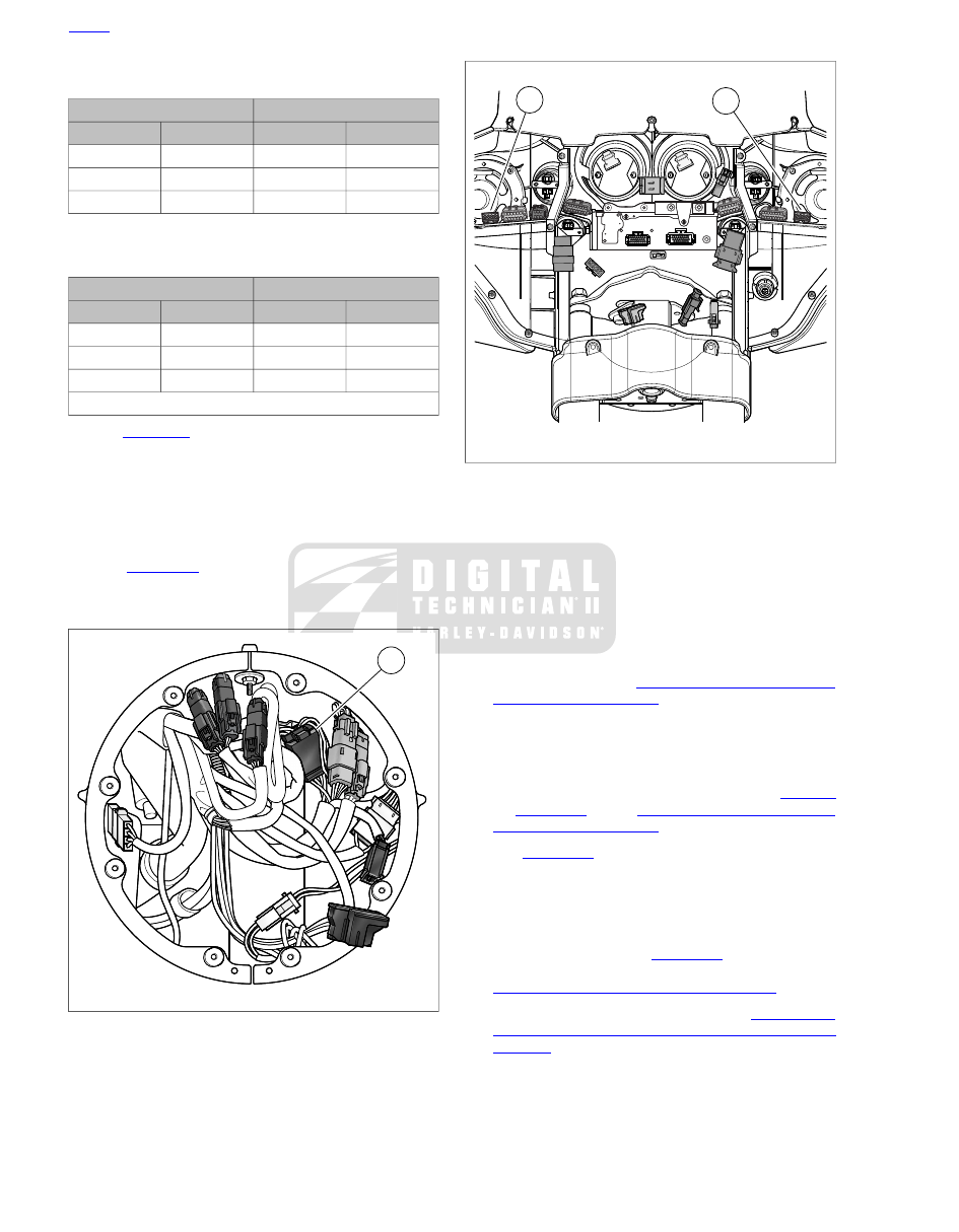
Table 7-9. Front Turn Signal Lamps [31] (Road King)
RIGHT SIDE
LEFT SIDE
CHAMBER
WIRE COLOR
CHAMBER
WIRE COLOR
1
Black
4
Blue (DOM)
2
Brown
5
Violet
3
Blue (DOM)
6
Black
Table 7-10. Front Turn Signal Lamps [31L/R] (fork
mounted fairing models)
RIGHT SIDE [31R]
LEFT SIDE [31L]
CHAMBER
WIRE COLOR
CHAMBER
WIRE COLOR
1
Blue
1
Blue
2
Brown
2
Violet
3
Black
3
Black
Note: Terminal 4 is reserved for the auxiliary lamp.
4.
See
. Remove two screws to release turn signal
lamp from mounting bracket.
NOTE
Be sure that chaser wire is of sufficient strength to pull terminals
through conduit without breaking. Wire lengths must also be
long enough so that free ends are not lost in conduit when
pulled.
5.
See
. Obtain three equal lengths of strong
flexible wire for use as chaser wires. Securely attach a
chaser wire to terminal of each wire.
1
sm03646
1. Front turn signal lamps [31]
Figure 7-47. Headlamp Nacelle (Road King models)
2
1
sm05085
1. Right front turn signal/auxiliary lamp [31R]
2. Left front turn signal/auxiliary lamp [31L]
Figure 7-48. Inner Fairing (fork mounted fairing models)
6.
Carefully pull wires to draw terminals through both sections
of conduit. For best results, pull one wire at a time.
7.
Remove chaser wire from terminals.
Installation: Flat Lens Style
1.
Lay old turn signal lamp next to
new
turn signal lamp and
cut wires to length.
2.
Strip 3/16 in. (4.8 mm) of insulation off wires and crimp on
new
terminals. See
3.
Secure chaser wires to terminals. Carefully draw terminals
back through conduit.
4.
Remove chaser wires.
5.
Install terminals into connector housing. Refer to
or
. See
6.
See
. Start two screws to secure turn signal
lamp to mounting bracket. Verify that conduit fits in slot at
back of bracket and is not pinched. Tighten screws to
30-60
in-lbs
(4.1-6.8 Nm).
7.
Connect front turn signal/auxiliary lamp connector.
8.
Road King models:
See
. Secure anchor to
fork stem nut lockplate. Install headlamp assembly. See
7.11 HEADLAMP: ALL EXCEPT ROAD GLIDE
.
9.
Fork mounted fairing models:
See
FAIRING AND WINDSHIELD: FORK MOUNTED FAIRING
MODELS
. Secure connector on T-stud at top of fairing
support brace. Verify that conduit is routed inboard using
relief in upper outboard corner of chrome skirt. Install outer
fairing.
7-40 2011 Touring Service: Electrical