Harley Davidson 2011 Touring Models. Service Manual - page 26
 

  Главная      Harley Davidson     Harley Davidson 2011 Touring Models. Service Manual


Search            copyright infringement  


Content      ..     24      25      26      27     ..


Harley Davidson 2011 Touring Models. Service Manual - page 26


7.12

HEADLAMP: ROAD GLIDE

HEADLAMP ADJUSTER ASSEMBLY

Removal

NOTE

Either headlamp assembly can be replaced individually without
removing the fairing. See

7.12 HEADLAMP: ROAD GLIDE,

Headlamp Bulb Replacement: Dual Headlamp Models

.

1.

Carefully pry headlamp outer trim from front of motorcycle.

2.

Remove four screws securing each headlamp assembly
to trim ring.

3.

Disconnect headlamp harnesses from bulbs and set
headlamp assemblies aside.

4.

See

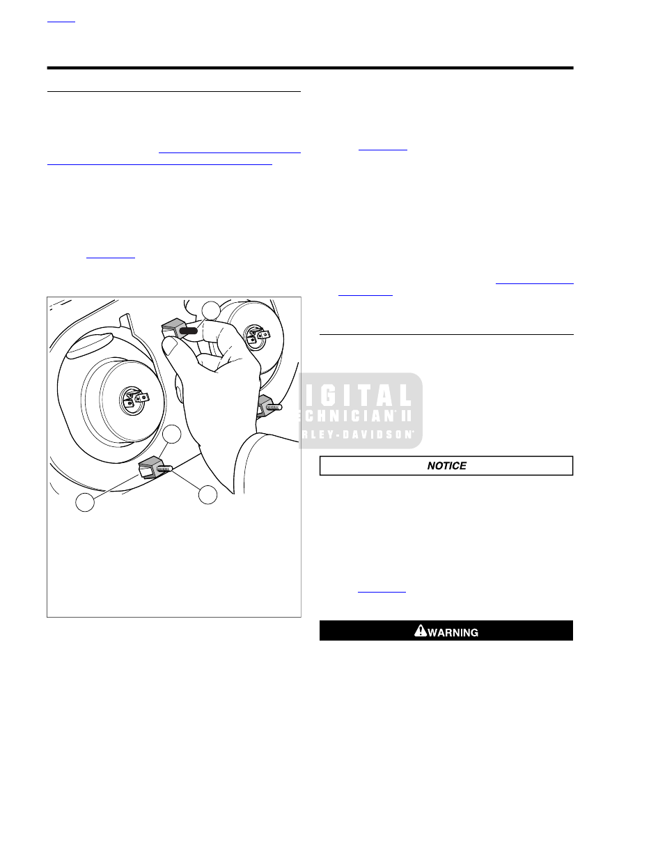
Figure 7-19

Reach into fairing and compress tabs

(2) on each mounting clip (4) and remove headlamp trim
ring assembly.

4

1

2

3

sm05125

1. Protective sleeve
2. Tab
3. Hex adjuster stud
4. Mounting clip

Figure 7-19. Compress Mounting Clips (shown with fairing

removed for clarity of illustration)

Repair

1.

Remove screw securing adjuster screw assembly.

2.

Remove mounting clip and mount plate from adjuster
screw

3.

Install mount plate on adjuster screw with arc oriented as
shown.

4.

Install mounting clip on adjuster screw.

5.

Install adjuster assembly on trim ring and tighten screw
to 35-45

in-lbs

(4.0-5.1 Nm).

Installation

NOTES

See

Figure 7-19

. Install protective sleeve on top center

stud of headlamp adjuster assembly.

Mounting clips should be inserted with the tabs (2) on the
sides, not top and bottom.

1.

Push headlamp trim ring assembly into position until tabs
on mounting clips engage outer fairing.

2.

Connect and install both headlamp assemblies. Tighten
screws to 15-25

in-lbs

(1.7-2.8 Nm).

3.

Install headlamp outer trim.

4.

Check headlamp alignment. See

1.21 HEADLAMP

ALIGNMENT

.

HEADLAMP BULB REPLACEMENT: DUAL
HEADLAMP MODELS

Removal

1.

Carefully pry headlamp bezel from front of motorcycle.

2.

Remove four screws securing headlamp assembly to trim
ring/adjuster assembly.

3.

Disconnect headlamp harness from bulb and remove
headlamp housing assembly.

Bulb Replacement

When replacement is required, use only the specified
sealed beam unit or bulb, available from a Harley-Davidson
dealer. An improper wattage sealed beam or bulb, can
cause charging system problems. (00209a)

NOTE

The headlamp uses a replaceable quartz halogen bulb which
is bulb is very delicate and must be handled with care.

1.

See

Figure 7-20

Remove rubber boot (1).

2.

Rotate retainer (2) counter-clockwise and remove.

Handle bulb carefully and wear eye protection. Bulb con-
tains gas under pressure, which, if not handled carefully,
could cause serious eye injury. (00062b)

3.

Remove and discard bulb.

HOME

7-24 2011 Touring Service: Electrical

Never touch the quartz bulb. Fingerprints will etch the
glass and decrease bulb life. Handle the bulb with paper
or a clean, dry cloth. Failure to do so could result in bulb
damage. (00210b)

4.

See

Figure 7-20

Install

new

bulb in headlamp housing.

Be sure tab (5) on bulb is aligned with slot (6) in bulb
housing.

5.

Install retainer (2) and rotate clockwise to secure.

6.

Install rubber boot (1) over retainer until flush with base
of bulb socket.

7.

HDI models:

Rotate position lamp bulb retainer 1/4 turn

counterclockwise to remove. Replace bulb and install bulb
retainer in lamp housing.

Installation

1.

Install headlamp assembly and tighten screws to 15-25

in-lbs

(1.7-2.8 Nm).

2.

Install headlamp bezel.

5

4

3

2

1

6

sm03614

1. Rubber boot
2. Retainer
3. Bulb
4. Headlamp housing
5. Tab
6. Slot

Figure 7-20. Headlamp Housing Assembly

HOME

2011 Touring Service: Electrical 7-25

7.13

AUXILIARY LAMPS AND BRACKETS

AUXILIARY LAMP BULB REPLACEMENT

Removal

1.

See

Figure 7-21

Loosen screw (3) and pull door (2) from

lip of lamp housing.

2.

Disconnect auxiliary lamp connector.

3.

See

Figure 7-22

. Remove nesting ring.

Handle bulb carefully and wear eye protection. Bulb con-
tains gas under pressure, which, if not handled carefully,
could cause serious eye injury. (00062b)

4.

Rotate bulb housing 1/4 turn counterclockwise and remove
from lens. Discard bulb/housing assembly.

Never touch the quartz bulb. Fingerprints will etch the
glass and decrease bulb life. Handle the bulb with paper
or a clean, dry cloth. Failure to do so could result in bulb
damage. (00210b)

Installation

1.

Install

new

bulb/housing assembly and rotate 1/4 turn

clockwise.

2.

See

Figure 7-22

. Place nesting ring on back of lens with

the concave side up.

3.

Secure harness connector to bulb housing.

4.

Place nesting ring on lamp housing and rotate until index
tab (2) engages slot at bottom of lamp housing.

5.

Hold nesting ring in place and rotate lens so that index
tabs (1) engage slots in nesting ring.

6.

See

Figure 7-21

Install lamp door over on lamp housing

with screw centered at bottom. Tighten door screw until
snug.

2

1

4

5

3

sm03617

1. Auxiliary lamp
2. Door
3. Door screw
4. Screw (2)
5. Mounting bracket

Figure 7-21. Auxiliary Lamp

1

2

1

sm03618

1. Lamp index tab
2. Nesting ring index tab

Figure 7-22. Auxiliary Lamp Assembly

HOME

7-26 2011 Touring Service: Electrical

AUXILIARY LAMP HOUSING

TOOL NAME

PART NUMBER

FLARE NUT SOCKET

SNAP-ON® FRX181

Removal

NOTE

See

Figure 7-25

. If replacing only the lamp housing, begin at

step 1. Start at step 2 if replacing the entire lamp assembly.

1.

Disassemble auxiliary lamp. See

7.13 AUXILIARY LAMPS

AND BRACKETS, Auxiliary Lamp Bulb Replacement

.

2.

Proceed as follows:

a.

Road King models:

See

Figure 7-23

Remove

headlamp assembly. See

7.11 HEADLAMP: ALL

EXCEPT ROAD GLIDE

. Disconnect auxiliary lamps

connector [73], 2-place Multilock.

b.

Fairing models:

See

Figure 7-24

. Remove outer

fairing. See

2.34 UPPER FAIRING AND WIND-

SHIELD: FORK MOUNTED FAIRING MODELS

.

Disconnect the left or right front turn signal/auxiliary
lamp connector [31L/R], 4-place Multilock, on T-stud
at top of left or right fairing support brace (outboard
side).

3.

Remove appropriate terminal(s) from socket housing.

Table 7-6. FLHR/C Auxiliary Lamps [73]

RIGHT SIDE

LEFT SIDE

CHAMBER

WIRE COLOR

CHAMBER

WIRE COLOR

2

Gray/Black

1

Gray/Black

Table 7-7. FLHTC/U, FLHTK Auxiliary Lamps [31L/R]

RIGHT SIDE [31R]

LEFT SIDE [31L]

CHAMBER

WIRE COLOR

CHAMBER

WIRE COLOR

4

Gray/Black

4

Gray/Black

Note: Terminals 1, 2 and 3 are reserved for the turn signal
lamp.

NOTE

For instructions on removing terminals, see

A.19 TYCO 070

MULTILOCK UNSEALED CONNECTOR

.

4.

See

Figure 7-21

. Remove two screws to release turn signal

lamp from mounting bracket.

5.

See

Figure 7-26

Obtain length of strong flexible wire for

use as mechanics wire. Feed wire through opening in
socket terminal and then loop back twisting end until tightly
coiled around longer strand.

NOTE

Be sure that mechanics wire is of sufficient strength to pull
terminal through conduit without breaking. Wire length must
also be long enough so that free end is not lost in conduit when
pulled.

6.

Carefully pull wire to draw socket terminal through conduit.

7.

Unravel mechanics wire to release socket terminal.

8.

Insert FLARE NUT SOCKET (Part No. Snap-on® FRX181)
at bottom of turn signal mounting bracket and remove
locknut from stud. Remove the turn signal mounting
bracket and clamp block.

9.

Remove auxiliary lamp (with Belleville washer and swivel
block) from the auxiliary lamp bracket.

2

1

sm03619

1. Front turn signal lamps [31]
2. Auxiliary lamps [73]

Figure 7-23. Headlamp Nacelle (Road King)

2

1

sm05085

1. Right front turn signal/auxiliary lamp [31R]
2. Left front turn signal/auxiliary lamp [31L]

Figure 7-24. Inner Fairing (fork mounted fairing models)

HOME

2011 Touring Service: Electrical 7-27

Installation

1.

Lay old auxiliary lamp next to

new

auxiliary lamp and cut

wire to length.

2.

Strip 3/16 in (4.8 mm) of insulation off wire and crimp on

new

socket terminal.

NOTE

For instructions on crimping terminals, see

A.19 TYCO 070

MULTILOCK UNSEALED CONNECTOR

.

3.

If removed, slide swivel block and Belleville washer down
wire onto auxiliary lamp stud. Be sure that rounded side
of swivel block and concave side of Belleville washer face
auxiliary lamp.

4.

Feed wire through slot at top of auxiliary lamp bracket and
insert threaded stud into forward slot. Slide clamp block
(rounded side up), turn signal mounting bracket and
locknut up wire onto auxiliary lamp stud at bottom of
bracket.

5.

Using FLARE NUT SOCKET (Part No. Snap-on®
FRX181), tighten locknut to 15-18 ft-lbs (20.3-24.4 Nm).

6.

Reattach mechanics wire to socket terminal and carefully
pull end of mechanics wire to draw socket terminal back
through conduit.

7.

Carefully remove mechanics wire to avoid damage to ter-
minal.

8.

Install terminal into socket housing. Refer to

Table 7-6

or

Table 7-7

.

NOTE

For instructions on installing terminals, see

A.19 TYCO 070

MULTILOCK UNSEALED CONNECTOR

.

9.

Connect front turn signal/auxiliary lamp connector.

10. Turn Ignition/Light Key Switch to IGNITION and test for

proper operation and alignment. Adjust if necessary.

11. See

Figure 7-21

. Start two screws to secure turn signal

lamp to mounting bracket. Verify that conduit fits in slot at
back of bracket and is not pinched. Alternately tighten
screws to 36-60

in-lbs

(4.1-6.8 Nm).

12. Proceed as follows:

a.

Road King models:

Install headlamp assembly. See

7.11 HEADLAMP: ALL EXCEPT ROAD GLIDE

.

b.

Fairing models:

Install connector on T-stud at top of

left or right fairing support brace (outboard side).
Verify that conduit is routed inboard using relief in
upper outboard corner of chrome skirt. Install outer
fairing. See

2.34 UPPER FAIRING AND WIND-

SHIELD: FORK MOUNTED FAIRING MODELS

.

13. Assemble auxiliary lamp, if necessary. See

7.13 AUXIL-

IARY LAMPS AND BRACKETS, Auxiliary Lamp Bulb
Replacement

.

sm03620

Figure 7-25. Auxiliary Lamp Housing

sm03621

Figure 7-26. Fix Mechanics Wire to Socket Terminal

AUXILIARY LAMP BRACKET

Removal

1.

Proceed as follows:

a.

Road King Models:

See

Figure 7-23

Remove

headlamp assembly. See

7.11 HEADLAMP: ALL

EXCEPT ROAD GLIDE

Disconnect auxiliary lamps

connector [73], white 2-place Multilock. Disconnect
front turn signal lamps connector [31], 6-place Multi-
lock, anchored in hole of fork stem nut lockplate (left
side).

b.

Fork Mounted Fairing Models:

See

Figure 7-24

.

Remove outer fairing. See

2.34 UPPER FAIRING

AND WINDSHIELD: FORK MOUNTED FAIRING
MODELS

Disconnect the left and right front turn

signal/auxiliary lamp connectors [31L/R], 4-place
Multilocks, on T-studs at top of left and right fairing
support braces (outboard sides).

HOME

7-28 2011 Touring Service: Electrical

2.

Proceed as follows:

a.

Road King Models:

Remove acorn nuts from fork

bracket studs.

b.

Fork Mounted Fairing Models:

Loosen screws in

upper and lower fork brackets.

3.

Remove auxiliary lamp bracket from motorcycle.

Installation

1.

Install auxiliary lamp bracket on motorcycle. Proceed as
follows:

a.

Road King Models:

Slide slots of auxiliary lamp

bracket onto upper and lower fork bracket studs.
Install acorn nuts on studs. Alternately tighten acorn
nuts to 72-108

in-lbs

(8.1-12.2 Nm) using a crosswise

pattern.

b.

Fork Mounted Fairing Models:

Slide slots of auxiliary

lamp bracket onto screws in upper and lower fork
brackets. Alternately tighten screws to 15-20 ft-lbs
(20-27 Nm) using a crosswise pattern.

2.

Proceed as follows:

a.

Road King Models:

Connect auxiliary lamps con-

nector [73], white 2-place Multilock. Connect front
turn signal lamps connector [31], 6-place Multilock.
Install anchor on connector into hole of fork stem nut
lockplate (left side). Install headlamp assembly. See

7.11 HEADLAMP: ALL EXCEPT ROAD GLIDE

.

b.

Fork Mounted Fairing Models:

Connect the left and

right front turn signal/auxiliary lamp connectors
[31L/R], 4-place Multilocks. Install connectors on T-
studs at top of left and right fairing support braces
(outboard sides). Verify that conduit is routed inboard
using reliefs in upper outboard corners of chrome
skirt. Install outer fairing. See

2.34 UPPER FAIRING

AND WINDSHIELD: FORK MOUNTED FAIRING
MODELS

.

ADJUSTMENT

See

1.21 HEADLAMP ALIGNMENT

for alignment procedures.

HOME

2011 Touring Service: Electrical 7-29

7.14

TAIL LAMP

TAIL LAMP BULB REPLACEMENT

Removal

1.

Remove two screws to release tail lamp assembly from
chrome base.

2.

See

Figure 7-27

. Disconnect tail lamp connector (3).

3.

Rotate bulb socket (4) 1/4 turn counterclockwise and
remove from tail lamp assembly. Pull bulb from socket.

Installation

1.

Coat base of

new

bulb with ELECTRICAL CONTACT

LUBRICANT (Part No. 99861-02). Install

new

bulb in

socket.

2.

Insert socket (4) into tail lamp assembly and rotate 1/4
turn clockwise.

3.

See

Figure 7-27

. Connect tail lamp connector (3).

4.

Place tail lamp into position against chrome base.

NOTE

Over tightening screws can crack the lens.

5.

Install two screws and tighten to 20-24

in-lbs

(2.3-2.7

Nm).

Be sure that all lights and switches operate properly before
operating motorcycle. Low visibility of rider can result in
death or serious injury. (00316a)

6.

Test tail lamp operation.

3

1

2

4

om01003

1. Lens
2. Base
3. 4-pin multilock connector
4. Bulb socket

Figure 7-27. Tail Lamp Assembly

CIRCUIT BOARD/CHROME BASE

Removal

1.

Remove two screws to release tail lamp assembly from
chrome base.

2.

See

Figure 7-27

Disconnect tail lamp connector (3).

3.

See

Figure 7-28

and

Figure 7-29

Disconnect remaining

connectors. To release socket housings of left and right
turn signal lamps, use a pick or small screwdriver to press
button.

4.

Remove screw at center of chrome base. Push chrome
base upward until it is free of fender and pull out of fender
hole.

5.

See

Figure 7-28

. Feed connector housings through

openings to inboard side of chrome base. For best results,
free the smaller socket housings first.

4

3

1

2

5

6

sm03624

1. Left turn signal lamp [18]
2. Right turn signal lamp [19]
3. Rear fender tip lamp [45]
4. Tail lamp [93]
5. Rear fender lights harness [94]
6. Opening

Figure 7-28. Rear Fender Lights Assembly

HOME

7-30 2011 Touring Service: Electrical

sm03625

Figure 7-29. Use Pick Tool to Release Left Turn Signal

Lamp Socket

6.

Remove pin housing/circuit board from chrome base.

Installation

1.

See

Figure 7-28

. Feed connector housings through

openings to outboard side of chrome base. For best res-
ults, feed the larger socket housings first.

2.

Fit bottom of chrome base into fender hole and push down
to align center hole with clip nut on fender flange.

3.

See

Figure 7-30

. Place pin housing over circuit board, if

removed.

4.

Insert index pins at back of pin housing into holes in
chrome base.

NOTE

Over tightening screw can crack the chrome base.

5.

Install screw (with captive washer) to secure pin
housing/circuit board. Tighten screw to 40-48

in-lbs

(4.5-

5.4 Nm).

6.

Install connector housings into circuit board.

7.

See

Figure 7-27

To avoid stressing wires, verify that tail

lamp conduit is positioned on the outboard side of the rear
fender tip lamp and left turn signal lamp conduit.

8.

Place tail lamp into position against chrome base.

NOTE

Over tightening screws can crack the lens.

9.

Install two screws and tighten to 20-24

in-lbs

(2.3-2.7

Nm).

Be sure that all lights and switches operate properly before
operating motorcycle. Low visibility of rider can result in
death or serious injury. (00316a)

10. Test lamp for proper operation.

H-D

USA

68830-98

sm03626

Figure 7-30. Place Pin Housing Over Circuit Board

REAR FENDER LIGHTS HARNESS: ALL
EXCEPT FLHX, FLTRX

Removal

NOTE

FLHTC models use a jumper harness between the fender
harness connector and the main harness connector located in
the left electrical caddy, which can be removed and installed
independent of the fender harness.

1.

Remove rear fender. See

2.46 REAR FENDER

.

2.

Remove tail lamp assembly from chrome base.

3.

See

Figure 7-28

. Disconnect connector (4) and set tail

lamp assembly aside. Disconnect connector (5) and feed
through opening to inboard side of fender.

4.

See

Figure 7-31

. Release turn signal lamp wires from

cable clips (3). On FLHTC/U, FLHTK models, release wire
from stamped fender clip (4).

5.

Release harness from channel in stud plate (2). Loosen
flange nuts if necessary.

6.

Remove adhesive conduit (1) with wire harness from
fender well.

7.

If replacing only conduit (1):

a.

Carefully cut adhesive conduit and remove wire har-
ness.

b.

Remove

rear

connector

from

harness.

See

B.1 CONNECTORS

.

HOME

2011 Touring Service: Electrical 7-31

2

5

3

3

4

6

7

1

sm03627

1. Adhesive conduit
2. Stud plate
3. T-stud cable clips (2)
4. Stamped fender clip
5. Cable strap
6. 0.88 in. (22.4 mm) between conduit and chrome

base hole

7. 1.43 in. (36.3 mm) between conduit and fender

seat screw centerline

Figure 7-31. Rear Fender Well

Installation

1.

Clean fender as follows:

a.

Thoroughly clean fender well with soap and water.
Do not use solvents or harsh chemicals that may
damage painted surfaces.

b.

Remove all residual adhesive using 3M General
Purpose Adhesive Remover (Part No. 051135).

c.

See

Figure 7-31

Using a soapy Scotch Brite® pad,

thoroughly clean fender well in area of adhesive
conduit.

d.

Rinse with clear water and thoroughly dry with a clean
white cloth. Repeat until clean cloth shows no evid-
ence of dirt.

e.

Swab area with isopropyl alcohol and allow to dry.

2.

If replacing only the adhesive conduit:

a.

Verify cable strap (3) is installed as shown in

Figure 7-32

to prevent rearward movement of the

harness.

b.

Draw harness through

new

conduit until progress is

halted by installed cable strap (3).

3.

Install connector housing on harness. See

B.1 CON-

NECTORS

. Refer to

Table 7-8

for proper wire location.

4.

See

Figure 7-31

Remove paper backing and lightly press

conduit in location shown in graphic.

5.

Use a wallpaper seam roller to press conduit securely in
place.

6.

Allow the adhesive 72 hours to fully cure. Installation of
the fender may proceed, but exercise caution to avoid
pulling or repositioning adhesive conduit.

7.

Feed forward connector housing of harness through hole
in front of fender.

8.

Capture harness in channel of stud plate (2). If loosened,
tighten flange nuts to 60-96

in-lbs

(6.8-10.9 Nm).

9.

Feed rear harness connectors through openings in fender
and capture turn signal lamp wires in cable clips (3). On
FLHTC/U, FLHTK models, capture rear fender tip lamp
wire in stamped fender clip (4).

10. See

Figure 7-28

. Mate tail lamp connectors (3, 4) to tail

lamp base.

11. Verify that tail lamp harnesses are routed as shown in

Figure 7-27

.

NOTE

Over-tightening screws can crack the lens.

12. Install tail lamp and tighten screws to 20-24

in-lbs

(2.3-

2.7 Nm).

13. Install rear fender. See

2.46 REAR FENDER

.

HOME

7-32 2011 Touring Service: Electrical

Table 7-8. Rear Fender Lights [94]

CHAMBER

NUMBER

WIRE

COLOR

CHAMBER

NUMBER

WIRE

COLOR

4

Red/Yellow

1

Orange/White

5

Violet

2

Brown

6

Black

3

Blue

1

2

4

6

5

3

sm04757

1. Connector [7B]
2. Conduit
3. Cable Strap
4. Adhesive Conduit
5. 0.25 in. (6.35 mm)
6. 8.75 in. (222.25 mm)

Figure 7-32. Install Cable Strap on Conduit

REAR FENDER LIGHTS HARNESS: FLHX,
FLTRX

Removal

1.

Remove left saddlebag and left side cover.

2.

See

Figure 7-33

. Cut cable straps (2, 3).

3.

Separate connector (1).

4.

See

Figure 7-34

. Cut cable straps (1).

5.

Release harness from molded clips (2) on fascia.

6.

Disconnect harness from fender tip lamp.

7.

Note harness routing and remove harness.

NOTE

Models intended for sale in Canada incorporate both a turn
signal light bar and tail lamp, and include an additional jumper
harness.

8.

Canadian Models:

See

Figure 7-35

.

a.

Remove rear fender. See

2.46 REAR FENDER

.

b.

Remove tail lamp lens.

c.

Disconnect jumper harness (2) from the rear fascia
lamp and the tail lamp.

d.

Release jumper harness from clamps (1, 3) and
remove from fender.

Installation

1.

Canadian Models:

See

Figure 7-35

.

a.

Route jumper harness (2) from tail lamp to the fascia
lamp and connect to each lamp.

NOTE

Over tightening screws can crack the lens.

b.

Install tail lamp lens and tighten screws to 20-24

in-

lbs

(2.3-2.7 Nm).

c.

Secure jumper harness with clamps (1, 3) and install
fender. See

2.46 REAR FENDER

.

2.

See

Figure 7-33

and

Figure 7-34

Route harness in

approximate position, passing behind frame and through
opening in left caddy.

3.

See

Figure 7-34

. Pass harness under antenna mount (3)

and secure harness in molded clips (2) on inside of fascia.
Connect to fender tip lamp. Pull harness up to remove
slack near fender tip lamp.

NOTE

Cable ties may also secure additional harnesses.

4.

Secure harness using

new

cable ties (1) around air valve

bracket and saddlebag support as shown.

5.

See

Figure 7-33

. Pull slack from harness and secure to

caddy with

new

cable strap (2).

6.

Mate connector (1) and secure harness with

new

anchored

cable straps (3).

7.

Install side cover and saddlebag.

2

1

3

sm06616

1. Connector
2. Cable strap
3. Cable strap, anchored

Figure 7-33. Rear Fender Lamps Harness, Antenna Cable

and Air Tube Routing

HOME

2011 Touring Service: Electrical 7-33

1

3

2

sm06617

1. Cable strap
2. Molded clip (2)
3. Antenna mount

Figure 7-34. Rear Fender Lamps Harness, Antenna Cable

and Air Tube Routing

1

2

3

4

sm06624

1. P-clamp
2. Jumper harness
3. Clamp, tee-stud
4. Turn signal lamps harnesses

Figure 7-35. Tail Lamp Jumper Harness (models with tail

lamp)

HOME

7-34 2011 Touring Service: Electrical

7.15

FENDER TIP LAMPS

FRONT FENDER TIP LAMP

Removal

1.

Insert blade of small screwdriver into slot at top of fender
tip lamp lens. Rotate end of screwdriver to unsnap lens
from lamp bracket.

2.

Holding Keps nuts at inboard side of rear fender, remove
two screws to release fender tip lamp bracket.

3.

See

Figure 7-38

. Disconnect front fender tip lamp con-

nector [143], 2-place Multilock.

Installation

1.

See

Figure 7-38

. Connect front fender tip lamp connector

[143], 2-place Multilock.

2.

With wires routed along bottom left side, place fender tip
lamp bracket into position aligning holes in bracket with
those in fender.

3.

Slide screws through bracket and fender holes and install
Keps nuts. Holding nuts at inboard side of fender, tighten
screws to 20-25

in-lbs

(2.3-2.8 Nm).

NOTE

Over tightening screws can crack the bracket or result in
scratching of the fender paint.

4.

Insert tab at bottom of lens into slot of fender tip lamp
bracket. Apply thumb pressure at top of lens until it snaps
into place.

Be sure that all lights and switches operate properly before
operating motorcycle. Low visibility of rider can result in
death or serious injury. (00316a)

5.

Turn the Ignition/Light Key Switch to IGNITION and test
lamp for proper operation.

FRONT FENDER TIP LAMP JUMPER
HARNESS

Removal

1.

FLHR:

Remove headlamp assembly. See

7.11 HEAD-

LAMP: ALL EXCEPT ROAD GLIDE

Disconnect the front

fender tip lamp jumper harness connector [32], 2-place
Multilock. See

Figure 7-36

.

2.

FLHTC/U, FLHTK:

Reaching in below the fairing cap on

the left side of the steering head, disconnect the front
fender tip lamp jumper harness connector [32], 2-place
Multilock. See

Figure 7-37

Remove outer fairing only if

necessary. See

2.34 UPPER FAIRING AND WIND-

SHIELD: FORK MOUNTED FAIRING MODELS

.

3.

Draw socket housing down to fender area.

4.

Carefully cut cable strap to release front fender tip lamp
wires from brake caliper hose.

5.

Remove terminals from socket housing.

NOTE

For instructions on removing terminals, see

A.19 TYCO 070

MULTILOCK UNSEALED CONNECTOR

.

6.

Place the motorcycle on a suitable lifting device with the
front wheel raised off the ground.

sm05089

Figure 7-36. Front Fender Tip Lamp Jumper Harness

Connector (Road King)

sm03628

Figure 7-37. Front Fender Tip Lamp Jumper Harness

Connector (models with fork mounted fairing)

7.

Remove front wheel. See

2.4 FRONT WHEEL

.

HOME

2011 Touring Service: Electrical 7-35

8.

From inboard side of front fender, remove two nuts to
release trim strip from left side of fender. See

Figure 7-39

.

9.

Pull wires and socket terminals through grommet to
inboard side of fender. See

Figure 7-40

. Reaching under

left side of fender, draw wires forward out from beneath
fender bracket.

10. Feed wires through oblong hole to outboard side of fender.

1

2

sm03629

1. Front fender tip lamp bracket
2. Front fender tip lamp connector [143]

Figure 7-38. Front Fender Tip Lamp Assembly

11. Insert blade of small screwdriver into slot at top of fender

tip lamp lens. Rotate end of screwdriver to unsnap lens
from lamp bracket.

12. Holding Keps nuts at inboard side of front fender, remove

two screws to release fender tip lamp bracket.

13. Disconnect front fender tip lamp connector [143], 2-place

Multilock, to release fender tip lamp assembly from jumper
harness. See

Figure 7-38

.

Installation

1.

Connect front fender tip lamp connector [143], 2-place
Multilock, to attach fender tip lamp assembly to jumper
harness. See

Figure 7-38

.

2.

Pull jumper harness conduit as close to fender tip lamp
connector [143] as possible, for the conduit is not easily
routed beneath the fender bracket.

3.

With conduit routed along bottom left side, place fender
tip lamp bracket into position aligning holes in bracket with
those in fender.

4.

Slide screws through bracket and fender holes and install
Keps nuts. Holding nuts at inboard side of fender, tighten
screws to 20-25

in-lbs

(2.3-2.8 Nm).

NOTE

Over tightening screws can crack the bracket or result in
scratching of the fender paint.

5.

Insert tab at bottom of lens into slot of fender tip lamp
bracket. Apply thumb pressure at top of lens until it snaps
into place.

6.

Route wire conduit inside trim strip and slide front tee bolt
over conduit. See

Figure 7-39

. Verify that second tee bolt

is in position at rear of trim strip.

1

5

2

3

4

sm03630

1. Fender tip lamp bracket
2. Tee bolt
3. Wire conduit
4. Trim strip
5. Oblong hole

Figure 7-39. Install Conduit in Trim Strip

1

2

sm03631

1. Grommet
2. Socket terminals

Figure 7-40. Pull Fender Tip Lamp Wires and Terminals

Through Fender Grommet

7.

Feed socket terminals and wires through oblong hole to
inboard side of fender.

NOTE

Use the rearmost oblong hole as the front may be used for
installation of certain P&A accessories.

8.

While removing slack from wires on outboard side of
fender, align tee bolts with fender holes. With trim strip

HOME

7-36 2011 Touring Service: Electrical

positioned against left side of fender, reach under fender
and install nuts on tee bolts. Alternately tighten nuts to
10-15

in-lbs

(1.1-1.7 Nm).

9.

Reaching under left side of fender, route wires of the
jumper harness rearward between tee bolt nut and fender
bracket and then beneath fender bracket to grommet. See

Figure 7-41

.

10. Feed socket terminals and wires through grommet to out-

board side of fender. See

Figure 7-40

.

NOTE

If any portion of the jumper harness is above the height of the
fender bracket, contact with the tire can cause chafing or other
damage. Damage to the wiring can lead to loss of lighting.

11. Remove slack from wires on inboard side of fender. Verify

that no portion of the jumper harness is above the height
of the fender bracket.

12. Install terminals into socket housing.

NOTE

For instructions on installing terminals, see

A.19 TYCO 070

MULTILOCK UNSEALED CONNECTOR

.

13. Route socket housing upward behind chrome skirt

(FLHTC/U, FLHTK) or through bottom of headlamp nacelle
(FLHR) to area beneath upper fork bracket. Connect front
fender tip lamp jumper harness connector [32].

NOTE

To connect jumper harness connector with the outer fairing
installed (FLHTC/U, FLHTK models), reach in below the fairing
cap on the left side of the steering head.

14. Install front wheel. See

2.4 FRONT WHEEL

.

15. Install

new

cable strap to secure front fender tip lamp wires

to brake caliper hose. See

Figure 7-42

.

16.

FLHR:

Install headlamp assembly. See

7.11 HEADLAMP:

ALL EXCEPT ROAD GLIDE

.

17.

FLHTC/U, FLHTK:

Install outer fairing, if removed. See

2.34 UPPER FAIRING AND WINDSHIELD: FORK
MOUNTED FAIRING MODELS

.

5

4

3

1

2

sm03632

1. Oblong hole
2. Jumper harness
3. T-bolt nut
4. Fender bracket
5. Grommet

Figure 7-41. Left Side Front Fender Well

sm03520

Figure 7-42. Capture Brake Hose and Front Fender Tip

Lamp Wires

Be sure that all lights and switches operate properly before
operating motorcycle. Low visibility of rider can result in
death or serious injury. (00316a)

18. Turn Ignition/Light Key Switch to IGNITION and test lamp

for proper operation.

REAR FENDER TIP LAMP

Removal

1.

Remove screws to release tail lamp assembly from chrome
base.

2.

See

Figure 7-43

. Disconnect tail lamp connector [93] (1).

Set tail lamp assembly aside.

3.

Disconnect rear fender tip lamp connector [45] (2).

4.

Feed harness through opening (3) in chrome base to
inboard side of rear fender.

5.

Remove harness from both clips on inner side of fender.

6.

See

Figure 7-44

Remove two screws (2) from inboard

side of fender to release fender tip lamp.

7.

Remove fender tip lamp from rear fender.

HOME

2011 Touring Service: Electrical 7-37

1

2

3

sm03633

1. Tail lamp connector [93]
2. Rear fender tip lamp connector [45]
3. Opening

Figure 7-43. Depress Button to Release Socket from Pin

Housing

Installation

1.

See

Figure 7-43

. Route rear fender tip lamp harness

through hole at bottom of fender and back through opening
(3) in tail lamp base. Attach rear fender tip lamp connector
[45] (2).

2.

Install rear fender tip lamp harness into both clips on inner
side of fender.

3.

See

Figure 7-44

. Place fender tip lamp into position and

secure with two screws (2). Tighten to 20-25

in-lbs

(2.3-

2.8 Nm).

4.

See

Figure 7-43

. Attach tail lamp connector [93] (1) to

base.

5.

Install tail lamp with two screws and tighten to 20-24

in-

lbs

(2.3-2.7 Nm).

NOTE

Over tightening screws can crack the lens or result in scratching
of the fender paint.

1

2

sm03634a

1. Fender Tip Lamp
2. Screw (2)

Figure 7-44. Rear Fender Tip Lamp

Be sure that all lights and switches operate properly before
operating motorcycle. Low visibility of rider can result in
death or serious injury. (00316a)

6.

Turn the Ignition/Light Key Switch to IGNITION and test
lamp for proper operation.

HOME

7-38 2011 Touring Service: Electrical

7.16

TURN SIGNAL LAMPS

TURN SIGNAL BULB REPLACEMENT:
BULLET STYLE

1.

See

Figure 7-45

Insert a coin or the blade of a small

screwdriver into the notch at the bottom of the lens cap.
Carefully twist until the lens cap pops out of the lamp
housing.

2.

Push bulb in and rotate counterclockwise. Pull bulb from
socket.

3.

Inspect condition of electrical contacts in socket. If
necessary, clean with a small wire brush and electrical
contact cleaner.

4.

Coat base of

new

bulb with ELECTRICAL CONTACT

LUBRICANT (Part No. 99861-02).

5.

Align pins on bulb with pin guides in bulb socket. Push

new

bulb in and turn clockwise to lock in place.

6.

Snap lens cap back into the lamp holder. Rotate lens to
position notch at bottom of lamp.

Be sure that all lights and switches operate properly before
operating motorcycle. Low visibility of rider can result in
death or serious injury. (00316a)

7.

Turn ignition on and test for proper operation.

om00343

Figure 7-45. Lens Cap Notch

TURN SIGNAL BULB REPLACEMENT: FLAT
LENS STYLE

1.

See

Figure 7-46

. Remove two screws to release lens from

lamp housing.

2.

Push bulb in and rotate counterclockwise to remove bulb
from socket.

3.

Inspect condition of electrical contacts in socket. If
necessary, clean with a small wire brush and electrical
contact cleaner.

4.

Liberally apply ELECTRICAL CONTACT LUBRICANT
(Part No. 99861-02) to contacts in socket and at bottom
of

new

bulb.

5.

Orient index pins on

new

bulb with pin guides inside bulb

socket. Push bulb in and turn clockwise to lock in place.

6.

Seat lens in lamp and install two screws.

Be sure that all lights and switches operate properly before
operating motorcycle. Low visibility of rider can result in
death or serious injury. (00316a)

7.

Test turn signal operation.

3

2

1

4

om01101

1. Screws (2)
2. Lens
3. Bulb
4. Lamp housing

Figure 7-46. Turn Signal Lamp Assembly: Flat Lens Style

FRONT TURN SIGNAL LAMP

Removal: Flat Lens Style

1.

Road King models:

See

Figure 7-47

Remove headlamp

assembly. See

7.11 HEADLAMP: ALL EXCEPT ROAD

GLIDE

. Disconnect front turn signal lamps connector.

2.

Fork mounted fairing models:

See

Figure 7-48

. Remove

outer fairing. See

2.34 UPPER FAIRING AND WIND-

SHIELD: FORK MOUNTED FAIRING MODELS

. Discon-

nect the left or right front turn signal/auxiliary lamp con-
nector.

3.

Remove terminal(s) from connector housing. Refer to

Table 7-9

or

Table 7-10

. See

A.19 TYCO 070 MULTILOCK

UNSEALED CONNECTOR

.

HOME

2011 Touring Service: Electrical 7-39


Content      ..     24      25      26      27     ..