Harley Davidson 2011 Touring Models. Service Manual - page 25
 

  Главная      Harley Davidson     Harley Davidson 2011 Touring Models. Service Manual


Search            copyright infringement  


Content      ..     23      24      25      26     ..


Harley Davidson 2011 Touring Models. Service Manual - page 25


7.5

TURN SIGNAL AND SECURITY MODULE
(TSM/TSSM/HFSM)

GENERAL

See

Figure 7-3

The Turn Signal Module (TSM) has two major

functions:

Control turn signals.

Serve as bank angle sensor.

The optional factory-installed security system provides the
same functionality as the TSM, but also includes security and
immobilization functions.

Two security system modules are available: The Turn Signal
Security Module (TSSM) for Japan/Korea markets and the
Hands Free Security Module (HFSM) for all other markets.

See the electrical diagnostic manual for complete details of
the TSM/TSSM/HFSM features and functions.

NOTE

The TSM/TSSM/HFSM cannot be repaired. Replace the unit
if it fails.

sm01275

Figure 7-3. TSM/TSSM/HFSM (TSM Shown)

REMOVAL

NOTE

If equipped with the optional "Harley-Davidson Smart Security
System," verify that the security status lamp in speedometer
face is not flashing before proceeding (security system dis-
armed).

1.

With the ignition key ON and the security fob present,
remove the main fuse.

2.

Remove right saddlebag and side cover.

3.

See

Figure 7-4

If equipped with ABS, release rear ABS

wheel speed sensor connector (1) from battery tray.

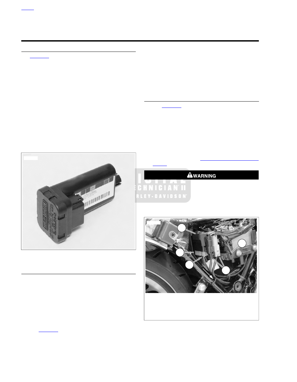
NOTE

It is not necessary to disconnect or remove the oxygen sensor
connectors (5) from the upper retainer (2).

4.

Pull out on bottom of module to release from retainer in
battery tray.

5.

Remove module from upper retainer (2) and disconnect
TSM/HFSM connector (3) and HFSM antenna jumper
harness connector (4) if equipped.

INSTALLATION

1.

See

Figure 7-4

. Connect TSM/HFSM connector (3) and

HFSM antenna jumper harness connector (4) if equipped.

2.

Place module into upper retainer (2) and push bottom of
module until it is secure in the retainer on the battery tray.

3.

If equipped, secure rear wheel speed sensor connector
(1) to retainer.

4.

Install right side cover and saddlebag.

5.

After installing ECM, the password learning procedure
must be performed. See

7.44 TSM/HFSM: PASSWORD

LEARN

.

Be sure that all lights and switches operate properly before
operating motorcycle. Low visibility of rider can result in
death or serious injury. (00316a)

6.

Test all turn signal functions. Test all security system
functions, if equipped.

1

2

3

4

5

sm06107a

1. Rear wheel speed sensor connector
2. Upper retainer
3. TSM/HFSM connector
4. HFSM antenna jumper harness connector
5. Oxygen sensor connectors

Figure 7-4. TSM/HFSM Module

HOME

7-8 2011 Touring Service: Electrical

HFSM ANTENNA

Removal

1.

Remove seat.

2.

See

Figure 7-5

Release HFSM antenna (2) from top

caddy.

3.

Disconnect HFSM antenna jumper harness.

4.

If necessary, remove HFSM antenna jumper harness as
follows:

a.

Remove HFSM module and disconnect antenna
jumper harness. See

7.5 TURN SIGNAL AND

SECURITY MODULE (TSM/TSSM/HFSM), Removal

.

b.

Cut cable strap retaining jumper harness and main
harness to rear downtube.

c.

Remove jumper harness through right side opening.

Installation

1.

Install HFSM antenna jumper harness as follows:

a.

Feed jumper harness down ahead of battery tray and
out through right side opening.

b.

Route jumper harness under ABS mounting area of
battery tray to the TSM/HFSM module.

c.

Connect jumper harness connector to HFSM module
and install HFSM module. See

7.5 TURN SIGNAL

AND SECURITY MODULE (TSM/TSSM/HFSM),
Installation

.

d.

Secure antenna harness and main harness to down
tube using a

new

cable strap.

2.

See

Figure 7-5

Connect HFSM antenna (2) to jumper

harness.

3.

Engage groove on HFSM antenna on tongue at front of
top caddy.

After installing seat, pull upward on seat to be sure it is
locked in position. While riding, a loose seat can shift
causing loss of control, which could result in death or
serious injury. (00070b)

4.

Install seat.

5.

Test all security system functions.

1

2

5

3

3

4

sm05698

1. Purge solenoid
2. HFSM antenna
3. Cable ties
4. Fastener
5. Hold-down (not visible)

Figure 7-5. Top Caddy

HOME

2011 Touring Service: Electrical 7-9

7.6

IGNITION COIL

REMOVAL

1.

Remove battery. See

1.23 BATTERY MAINTENANCE

.

2.

See

Figure 7-6

. Unplug rear and front spark plug wires (1,

2) from ignition coil.

3.

Remove ignition coil connector [83] (3).

4.

See

Figure 7-7

Remove screws (2) and battery hold-down

bracket (3).

5.

Loosen ground terminal nut (4). While holding ground
terminal wires out of the way, remove ignition coil (1).

INSTALLATION

1.

See

Figure 7-7

While holding ground terminal wires out

of the way, place ignition coil (1) into position.

2.

Install battery hold-down bracket (3) and screws (2).
Tighten screws to 32-40

in-lbs

(3.6-4.5 Nm).

3.

Place ground terminal wires in proper position and tighten
nut (4) to 50-90

in-lbs

(5.7-10.2 Nm) .

4.

See

Figure 7-6

Install ignition coil connector [83] (3).

5.

Connect rear (1) and front (2) spark plug wires to ignition
coil.

6.

Install battery. See

1.23 BATTERY MAINTENANCE

.

1

2

3

sm06036a

1. Rear spark plug wire
2. Front spark plug wire
3. Ignition coil connector [83]

Figure 7-6. Spark Plug Wires

4

2

3

2

1

sm06037

1. Ignition coil
2. Screw (2)
3. Battery hold-down bracket
4. Ground terminal nut

Figure 7-7. Ignition Coil

HOME

7-10 2011 Touring Service: Electrical

7.7

SYSTEM FUSES AND RELAYS

MAIN FUSE

Removal

1.

Remove left side saddlebag. See

2.26 SADDLEBAGS

.

2.

Remove left side cover.

3.

See

Figure 7-8

Pull main fuse from main fuse holder.

Installation

1.

See

Figure 7-8

Insert main fuse into main fuse holder.

2.

Install left side cover.

3.

Install left side saddlebag. See

2.26 SADDLEBAGS

.

MAIN FUSE HOLDER

Removal

1.

Remove left side saddlebag. See

2.26 SADDLEBAGS

.

2.

Remove left side cover.

3.

Pull main fuse from fuse holder.

4.

Remove battery. See

1.23 BATTERY MAINTENANCE

.

5.

Inboard of left side caddy:

a.

Cut front cable strap to release main harness bundle
and main power cable (to main fuse holder). Remove
and discard cable strap.

b.

Push up on tongue at bottom of harness cover to
release from slot in caddy, and then rotate up and
disengage hinges.

c.

Press latches on main fuse holder and pull from hole
in caddy.

NOTE

If further disassembly of the left side caddy is necessary, see

7.8 ELECTRICAL CADDIES

.

6.

Remove socket terminals from main fuse holder. See

A.7 DELPHI 800 METRI-PACK SEALED MAIN FUSE
HOUSING

.

Installation

1.

Install socket terminals into main fuse holder. See

A.7 DELPHI 800 METRI-PACK SEALED MAIN FUSE
HOUSING

.

2.

Inboard of left side caddy:

a.

Push main fuse holder into hole until it locks in place.

b.

Install

new

cable strap through front slot in caddy

capturing main harness bundle and main power cable
(to main fuse holder).

c.

Engage hinges and rotate harness cover down over
main harness bundle. Push up on tongue at bottom
of cover to engage slot in caddy.

NOTE

If further assembly of the left side caddy is necessary, see

7.8 ELECTRICAL CADDIES

.

3.

Install battery. See

1.23 BATTERY MAINTENANCE

.

4.

Insert main fuse into main fuse holder.

5.

Install left side cover.

6.

Install left side saddlebag. See

2.26 SADDLEBAGS

.

SYSTEM FUSES AND RELAYS

NOTE

Touring model motorcycles use a common fuse block cover.
Actual fuse use may vary based on model and options.

Removal

1.

Remove left side saddlebag. See

2.26 SADDLEBAGS

.

2.

Remove left side cover.

3.

Pull main fuse from fuse holder.

4.

Push up on tongue at bottom of fuse block cover to release
from slot in caddy, and then rotate up and disengage
hinge.

5.

See

Figure 7-8

. Remove system fuse/relay from fuse

block. Replace fuse if the element is burned. Automotive
type ATO fuses are used.

Installation

1.

See

Figure 7-8

. Install system fuse/relay in fuse block.

2.

Engage hinge and rotate fuse block cover down over fuse
blocks. Push up on tongue at bottom of cover to engage
slot in caddy.

3.

Insert main fuse into fuse holder.

4.

Install left side cover.

5.

Install left side saddlebag. See

2.26 SADDLEBAGS

.

HOME

2011 Touring Service: Electrical 7-11

1

2

3

4

5

6

7

13

14

15

18

19

20

17

21

22

11

12

10

9

16

8

23

om01155d

17.

9.

1.

Brake relay

Exhaust control (15 A)

Brake (15 A)

2.

18.

10.

Accessory (15 A)

Headlamp (15 A)

Fuel pump (15 A)

11.

3.

19.

System relay

P&A (15 A)

Lights (15 A)

20.

12.

4.

Spare (15 A)

Start relay

Radio power (15 A)

5.

21.

13.

Radio memory (15 A)

ABS (30 A)

P&A ignition (2 A max)

14.

6.

22.

Instruments (15 A)

Battery (15 A)

Spare (30 A)

23.

15.

7.

Main fuse (40 A)

Ignition (15 A)

ECM power (15 A)

8.

16.

Power outlet (15 A) (if
equipped)

Lighting relay

Figure 7-8. Fuses

FUSE BLOCKS

Removal

1.

Remove left side caddy as necessary to release fuse
blocks. See

7.8 ELECTRICAL CADDIES

.

2.

Remove system fuses and relays from fuse blocks.

3.

Remove socket terminals from fuse blocks. See

A.4 DELPHI 280 METRI-PACK UNSEALED CON-
NECTORS

.

Installation

1.

Install socket terminals into fuse blocks. See

A.4 DELPHI

280 METRI-PACK UNSEALED CONNECTORS

.

2.

See

Figure 7-8

Install system fuses and relays into fuse

blocks.

3.

Install fuse blocks into left side caddy. Install left side
caddy. See

7.8 ELECTRICAL CADDIES

.

HOME

7-12 2011 Touring Service: Electrical

7.8

ELECTRICAL CADDIES

TOP CADDY

Removal

1.

Remove seat. See

2.25 SEAT

.

2.

See

Figure 7-9

Remove HFSM antenna (4), if present.

3.

Lift up on ECM (3) until free of caddy.

4.

Remove screws (2).

5.

Lift up on top caddy and slide purge valve solenoid (5)
from front caddy, if present. Remove front caddy.

Installation

1.

See

Figure 7-9

Install purge valve solenoid (5) on front

caddy (1) and place caddy into position over battery.

2.

Install both screws (2). Tighten screws to 72-96

in-lbs

(8.1-10.9 Nm).

3.

Install ECM (3). Make sure holes in ECM are positioned
over alignment pins (6).

4.

Install HFSM antenna (4) onto caddy, if present.

5.

Install seat. See

2.25 SEAT

.

6

1

2

3

4

5

sm06092

1. Front caddy
2. Screw (2)
3. ECM
4. HFSM antenna
5. Purge valve solenoid
6. Alignment pin (2)

Figure 7-9. Top Caddy

LEFT SIDE CADDY

Removal

1.

Remove left side saddlebag. See

2.26 SADDLEBAGS

.

2.

Remove left side cover.

3.

Remove seat. See

2.25 SEAT

.

4.

See

Figure 7-10

Remove main fuse (3).

5.

Disconnect rear fender lights harness connector (1) and
slide connector body off of mounting tab.

6.

Cut cable strap (4) securing excess wire loop for AM/FM
antenna, if used.

7.

Disconnect siren (8), if installed, and remove from caddy.

8.

Remove ABS diode pack (5), if installed, data link con-
nector (6), and fuse block cover (7) from caddy.

9.

Remove screws (2).

1

3

2

2

8

7

6

5

4

sm06100a

1. Rear fender lights harness
2. Screw (2)
3. Main fuse
4. Cable tie
5. ABS diode pack
6. Data link connector
7. Fuse block cover
8. Siren (if equipped)

Figure 7-10. Caddy Components

10. See

Figure 7-11

. Remove front and rear cable straps (1,

4).

11. Remove harness cover (11).

12. Remove wires from square shaped opening (9).

13. From back side of caddy, squeeze tabs at top and bottom

of main fuse holder (15) and pull away from left-side caddy.

14. On back side of caddy, pull tabs holding fuse block (13)

to caddy and remove fuse block from back side of caddy.

Installation

1.

See

Figure 7-11

Insert fuse block (13) from back side of

caddy. Make sure tabs on caddy are secured to top and
bottom of fuse block.

2.

Insert main fuse holder (15) into caddy. Make sure the
tabs on the top and bottom of the fuse holder are fastened
to the caddy.

HOME

2011 Touring Service: Electrical 7-13

3.

Route wires for siren, data link connector, ABS diode pack,
and excess wire loop for AM/FM antenna, if used, through
square shaped opening (9).

4.

Install harness cover (11).

5.

Secure wires with front and rear cable straps (1, 4).

6.

See

Figure 7-10

Install screws (2). Tighten to 72-96

in-

lbs

(8.1-10.9 Nm).

7.

Install ABS diode pack (5), if ABS installed, data link con-
nector (6), and fuse block cover (7) to caddy.

8.

Install siren (8), if used and attach electrical connector to
siren.

9.

Attach excess wire loop for AM/FM antenna to caddy using
a

new

cable tie (4).

10. Connect rear fender lights harness connector (1) and slide

connector body onto mounting tab.

11. Install main fuse (3).

After installing seat, pull upward on seat to be sure it is
locked in position. While riding, a loose seat can shift
causing loss of control, which could result in death or
serious injury. (00070b)

12. Install seat. See

2.25 SEAT

.

13. Install left side cover.

14. Install left side saddlebag. See

2.26 SADDLEBAGS

.

Be sure that all lights and switches operate properly before
operating motorcycle. Low visibility of rider can result in
death or serious injury. (00316a)

15. Turn ignition on and test all lights and switches for proper

operation.

HOME

7-14 2011 Touring Service: Electrical

6

16

1

7

2

3

12

5

5

17

9

4

14

13

2

3

1

17

11

9

4

10

10

10

15

8

sm04387a

10.

1.

AM/FM Antenna harness

Front cable strap

2.

11.

Main harness bundle

Harness cover

12.

3.

Harness cover tongue slot

Main power cable

4.

13.

Rear cable strap

Fuse block

14.

5.

Main fuse

Data link connector [91]

6.

15.

ABS diode pack [201]

Main fuse holder

16.

7.

Tour-Pak harness

P&A siren connector [142]

8.

17.

Siren compartment/retaining latches

Rear fender lights harness [7]

9. Square shaped opening

Figure 7-11. Left Side Caddy (Typical)

BATTERY TRAY

Removal

1.

Remove battery. See

1.23 BATTERY MAINTENANCE

.

2.

Remove rear wheel. See

2.5 REAR WHEEL

.

3.

Remove left side caddy. See

7.8 ELECTRICAL CADDIES,

Left Side Caddy

.

HOME

2011 Touring Service: Electrical 7-15

4.

If Tour-Pak harness is routed through side of battery tray,
disconnect Tour-Pak connectors and pull harness away
from battery tray.

5.

Remove ignition coil. See

7.6 IGNITION COIL

.

6.

Remove ABS module, if equipped. See

C.2 ABS

MODULE

.

7.

Pull TSM/HFSM away from battery tray. See

7.5 TURN

SIGNAL AND SECURITY MODULE (TSM/TSSM/HFSM)

.

8.

If active exhaust actuator is not used, disconnect actuator
connector from battery tray.

9.

Remove four screws securing battery tray to frame.

10. Pull battery tray rearward out through frame.

Installation

1.

Install battery tray in from behind frame.

2.

Install four screws securing battery tray to frame. Tighten
to 72-96

in-lbs

(8.1-10.9 Nm).

3.

If active exhaust actuator is not used, connect actuator
connector to battery tray.

4.

Install TSM/HFSM onto battery tray. See

7.5 TURN

SIGNAL AND SECURITY MODULE (TSM/TSSM/HFSM)

.

5.

Install ABS module, if equipped. See

C.2 ABS MODULE

.

6.

Install ignition coil. See

7.6 IGNITION COIL

.

7.

If equipped with Tour-Pak, route harness through side of
battery tray and connect Tour-Pak connectors. Install cable
ties to secure harness.

8.

Install left side caddy. See

7.8 ELECTRICAL CADDIES,

Left Side Caddy

.

9.

Install rear wheel. See

2.5 REAR WHEEL

.

10. Install battery and top caddy. See

1.23 BATTERY MAIN-

TENANCE

.

After installing seat, pull upward on seat to be sure it is
locked in position. While riding, a loose seat can shift
causing loss of control, which could result in death or
serious injury. (00070b)

11. Install seat.

2.25 SEAT

.

Be sure that all lights and switches operate properly before
operating motorcycle. Low visibility of rider can result in
death or serious injury. (00316a)

12. Turn ignition on and test switches and lights for proper

operation.

HOME

7-16 2011 Touring Service: Electrical

7.9

SECURITY SIREN

REMOVAL

1.

Remove left side saddlebag. See

2.26 SADDLEBAGS

.

2.

Remove left side cover.

3.

With security fob present, turn ignition on.

4.

See

Figure 7-12

. Remove main fuse (3).

5.

Disconnect security siren connector [142] (1).

6.

Remove security siren (2).

INSTALLATION

1.

See

Figure 7-12

. Install security siren (2).

2.

Connect security siren connector [142] (1).

3.

Install main fuse (3) into holder.

4.

Install left side cover.

5.

Install left side saddlebag. See

2.26 SADDLEBAGS

.

1

2

3

sm06079

1. Security siren connector [142]
2. Security siren
3. Main fuse

Figure 7-12. Security Siren

HOME

2011 Touring Service: Electrical 7-17

7.10

STARTER

GENERAL

The starter is made up of a field coil assembly, solenoid
assembly and drive assembly. The repair instructions contained
in this section are divided into two major service areas for the
solenoid assembly and drive assembly.

NOTES

For troubleshooting and diagnostic information on the
solenoid assembly and drive assembly, see the electrical
diagnostic manual for this motorcycle.

Any damaged paint should be touched up after assembly
prior to installation using the appropriate touch up paint.
Follow the directions provided with the paint. Paint flaking
does not require the starter to be replaced.

REMOVAL

1.

Remove seat. See

2.25 SEAT

.

Disconnect negative (-) battery cable first. If positive (+)
cable should contact ground with negative (-) cable con-
nected, the resulting sparks can cause a battery explosion,
which could result in death or serious injury. (00049a)

2.

Remove battery negative (-) cable (black) from battery.

NOTE

The battery positive cable and power wire for the main fuse
are crimped together at the starter ring terminal. Both must be
replaced as an assembly if either requires replacement. See

A.7 DELPHI 800 METRI-PACK SEALED MAIN FUSE
HOUSING

for removal of power wire from main fuse connector.

3.

Remove battery positive and main fuse power cable ring
terminal from starter solenoid stud.

4.

Remove starter solenoid connector [128] at front of starter.

5.

Remove engine oil filler cap/dipstick. Cover fill spout with
clean shop cloth to keep out dirt and debris.

6.

Remove starter front and rear mounting screws.

7.

Remove starter from motorcycle. Exercise caution to avoid
losing the ring dowels.

DRIVE ASSEMBLY

Disassembly

1.

Remove screw to release end cover, if equipped.

2.

Remove two nuts to release end cover bracket from
through bolts, if equipped.

3.

See

Figure 7-13

. Pull up rubber boot (1) and remove hex

nut with captive lockwasher to release field wire from ter-
minal post on solenoid housing.

4.

Loosen two through bolts (2) to release field coil housing
from solenoid housing.

5.

Remove armature housing (3) keeping all contents
together for reassembly.

NOTE

Do not remove armature and brush plate from housing.
Replacement parts for components in the armature housing
are not available.

6.

Remove two screws to release drive housing from solenoid
housing.

7.

Use a rubber mallet to separate drive and solenoid hous-
ings, if necessary.

8.

Remove idler gear (5) from bearing cage in drive housing.
Remove bearing cage with five roller bearings (6) from
shaft in drive housing.

9.

Push on end of drive shaft to remove clutch starter sub
assembly (7) from drive housing.

10. Remove solenoid spring and ball from the output shaft of

the clutch starter sub assembly.

HOME

7-18 2011 Touring Service: Electrical

5

3

1

4

2

6

7

sm06871c

1. Rubber boot
2. Field coil housing through bolts
3. Armature housing
4. Screws (2)
5. Idler gear
6. Bearing cage with five roller bearings
7. Clutch starter sub-assembly

Figure 7-13. Clutch Starter Sub-Assembly and Housing

Inspection

1.

Inspect two O-rings in and on drive housing for cuts, tears
or signs of deterioration.

2.

See

Figure 7-13

Make sure that the idler gear (5) rotates

freely without drag or sticking.

3.

Inspect idler gear once removed from idler bearings and
replace starter motor if the gear is pitted, scored, rounded,
cracked, chipped or worn.

4.

Inspect roller bearings (6). Bearings must rotate freely
without drag or sticking. Replace starter motor if the
bearings are pitted or grooved.

5.

Inspect the steel ball for wear, pitting, surface breakdown
or other damage. Replace if necessary.

NOTE

If the solenoid return spring is not in working condition, the
entire starter motor must be replaced.

Assembly

1.

See

Figure 7-13

. Lubricate parts with high temperature

grease, such as LUBRIPLATE 110, during assembly and
install bearing cage with five roller bearings (6) onto shaft

in drive housing. Be sure that all five roller bearings are
installed in grooves of bearing cage. Install idler gear (5)
over bearing cage.

2.

Lubricate bearings with LUBRIPLATE 110 before installa-
tion, if necessary, and install

new

clutch starter sub

assembly (7) in drive housing seating the larger bearing
in the counterbore.

3.

Apply a light film of LUBRIPLATE 110 to solenoid plunger
shaft. Install return spring on solenoid plunger shaft.

NOTE

Before mating the solenoid and drive housings, apply a thin
layer of Harley-Davidson High-Performance Sealant (gray)
(Part No. 99650-02) to drive housing to act as a seal between
the two housings.

4.

Mate the solenoid and drive housings and install two hex
screws. Alternately tighten hex screws until snug.

5.

Install through bolts to fasten field coil to solenoid housing.
Tighten through bolts to 39-65

in-lbs

(4.4-7.3 Nm).

6.

Attach field wire ring terminal to short post on solenoid
housing and install hex nut with captive lockwasher.
Tighten hex nut to 70-90

in-lbs

(7.9-10.2 Nm). Cover field

wire ring terminal with rubber boot (1).

HOME

2011 Touring Service: Electrical 7-19

7.

Install end cover bracket, if equipped, onto threaded end
of through bolts, if equipped. For proper orientation, the
longest end of the bracket (before the bend) must be on
the field wire side. Install two nuts and tighten until snug.

8.

Install screw to fasten end cover to end cover bracket, if
equipped. Tighten screw to 90-110

in-lbs

(10.2-12.4 Nm).

SOLENOID

Cover and Plunger Removal

1.

See

Figure 7-14

. Remove the cover:

a.

Remove the three fasteners (1).

b.

Remove the cover (2).

c.

Remove the gasket (3).

2.

Remove the plunger (4) with the spring (5).

4

3

5

1

2

sm06876

1. Fasteners
2. Cover
3. Gasket
4. Plunger
5. Spring

Figure 7-14. Soleniod Plunger

Short Post Contact: Starter

1.

Disassemble the short post contact:

a.

Remove the starter ring terminal hex nut and the ring
terminal from the post.

b.

See

Figure 7-15

. Remove the jamnut (8), the wave

washer (7), the O-ring (6) and the round bushing (5):

c.

Remove the post bolt (1).

d.

Remove the hold-in terminal (2) from the post bolt.

e.

Remove the contact plate (3) and the square bushing.

2.

Assemble the short post contact:

a.

Insert the square bushing into the housing.

b.

Install the contact plate with the 90 degree part of the
contact plate against the solenoid winding.

c.

Install the post bolt through the hold-in terminal, the
contact plate and the square bushing.

d.

Install the round bushing, the O-ring, the wave washer
and the jamnut.

1

8

4

2

5

6

7

3

sm06877

1. Post bolt
2. Hold-in terminal
3. Contact plate
4. Square bushing
5. Round bushing
6. O-ring
7. Wave washer
8. Jamnut

Figure 7-15. Short Post Contact (starter)

Long Post Contact: Battery Positive

1.

See

Figure 7-16

Remove the long post contact:

a.

Remove hex nut (9).

b.

Remove the jamnut (8), the wave washer (7) and the
O-ring (6) and the round bushing (5).

c.

Remove the post bolt (4), the contact plate (3), the
square bushing (2) and the paper insulator (1).

2.

Install the long post contact:

a.

Insert the square bushing through the paper insulator
into the housing.

b.

Install the contact plate with the foot against the
solenoid winding.

c.

Install the post bolt.

HOME

7-20 2011 Touring Service: Electrical

NOTE

Check that the index pin on the round bushing fits the blind
hole in the housing.

d.

Install the round bushing, the O-ring, the wave washer
and the jamnut.

7

9

1

5

8

6

2

3

4

sm06878a

1. Paper insulator
2. Square bushing
3. Contact plate
4. Post bolt
5. Round bushing
6. O-ring
7. Wave washer
8. Jamnut
9. Hex nut

Figure 7-16. Long Post Contact (battery)

Plunger and Cover Installation

1.

Apply LUBRIPLATE 110 to the plunger shaft and install
the spring.

2.

Install the plunger and spring in the housing.

3.

While compressing the plunger, alternately tighten the
contact post jamnuts to 65-80

in-lbs

(7.3-9.0 Nm).

4.

Check that the contact plates are aligned to the solenoid
winding.

5.

Install the cover:

a.

Install a

new

gasket on the cover.

b.

Install the cover.

c.

Install the fasteners and tighten until snug.

6.

Install the starter ring terminal.

7.

Install and tighten the hex nut to 70-90

in-lbs

(7.9-10.2

Nm).

INSTALLATION

1.

Verify that two ring dowels are installed in the primary
chaincase or starter flange.

2.

Lubricate O-ring on starter and bore of primary chaincase
with light film of clean primary chaincase lubricant.

3.

Apply a drop of Loctite Threadlocker 243 (blue) to the
threads of the starter mounting screws.

4.

Move starter into its installed position and start both
mounting screws.

5.

Tighten starter mounting screws to 25-27 ft-lbs (33.9-36.6
Nm).

6.

Remove shop cloth over fill spout and install engine oil
filler cap/dipstick at top of transmission case.

7.

Install battery positive cable on stud of solenoid. Install
hex nut and tighten to 70-90

in-lbs

(7.9-10.2 Nm). Pull

down rubber boot over terminal connections.

8.

Install starter solenoid connector [128] at front of starter.

Do not over-tighten bolts on battery terminals. Use
recommended torque values. Over-tightening battery ter-
minal bolts could result in damage to battery terminals.
(00216a)

9.

Connect battery negative (-) cable to battery and tighten
bolt to 60-70

in-lbs

(6.8-7.9 Nm).

10. Install seat. See

2.25 SEAT

.

HOME

2011 Touring Service: Electrical 7-21

7.11

HEADLAMP: ALL EXCEPT ROAD GLIDE

HEADLAMP: SINGLE HEADLAMP MODELS

Removal

1.

Remove screw at bottom of headlamp door (chrome ring).
Remove headlamp door.

2.

See

Figure 7-17

Remove screws securing headlamp

assembly.

3.

Remove headlamp connector from headlamp bulb.

sm03514

Figure 7-17. Headlamp Retaining Screws (typical)

Bulb Replacement

When replacement is required, use only the specified
sealed beam unit or bulb, available from a Harley-Davidson
dealer. An improper wattage sealed beam or bulb, can
cause charging system problems. (00209a)

NOTE

The headlamp uses a replaceable quartz halogen bulb which
is very delicate and must be handled with care.

1.

Remove headlamp assembly.

2.

Remove rubber boot at back of housing.

3.

See

Figure 7-18

. Release wire retaining clip (1) from

retainer (2). Swing wireform out of the way.

NOTE

It may be necessary to loosen retainer screw 1/2-1 turn to
release wireform.

Handle bulb carefully and wear eye protection. Bulb con-
tains gas under pressure, which, if not handled carefully,
could cause serious eye injury. (00062b)

4.

Remove and discard bulb.

Never touch the quartz bulb. Fingerprints will etch the
glass and decrease bulb life. Handle the bulb with paper
or a clean, dry cloth. Failure to do so could result in bulb
damage. (00210b)

5.

Install

new

bulb. Align the tab on the bulb with the notch

in the headlamp housing.

6.

See

Figure 7-18

. Rotate wire retaining clip (1) into place

and latch under lip of retainer (2).

NOTE

If retainer screw was loosened to release wire retaining clip,
hold retainer in place and tighten screw until snug. Verify that
reflector cone is still centered under decorative logo. If it is not,
loosen retainer screw and repeat step until the proper results
are achieved.

7.

Install rubber boot at back of housing.

8.

HDI models:

Rotate position lamp bulb retainer 1/4 turn

counterclockwise to remove. Replace bulb and install bulb
retainer in lamp housing.

9.

Install headlamp assembly.

1

2

sm05135

1. Wire retaining clip
2. Retainer

Figure 7-18. Wire Retaining Clip

Installation

1.

Install headlamp connector on headlamp bulb.

HOME

7-22 2011 Touring Service: Electrical

2.

Install headlamp assembly and tighten screws to:

a.

Non-fairing equipped:

9-18

in-lbs

(1.0-2.0 Nm).

b.

Fairing equipped:

22-32

in-lbs

(2.5-3.6 Nm).

3.

Fit the headlamp door spring into slot at top of headlamp
housing and secure the headlamp door (chrome ring) with
screw. Tighten to 9-18

in-lbs

(1.0-2.0 Nm).

HOME

2011 Touring Service: Electrical 7-23


Content      ..     23      24      25      26     ..