Harley Davidson 2011 Touring Models. Service Manual - page 7
 

  Главная      Harley Davidson     Harley Davidson 2011 Touring Models. Service Manual


Search            copyright infringement  


Content      ..     5      6      7      8     ..


Harley Davidson 2011 Touring Models. Service Manual - page 7


1

2

3

sm00050

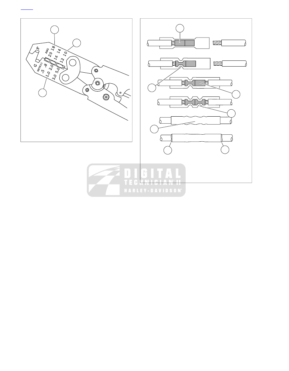
1. Red connector die
2. Blue connector die
3. Yellow connector die

Figure A-62. Packard Crimping Tool (HD-38125-8)

1

1

4

2

2

4

3

sm00051

1. Wire lead in metal insert
2. Crimp metal insert
3. Center of crimp
4. Melted sealant

Figure A-63. Sealed Splice Connector

HOME

A-40 2011 Touring Service: Appendix A Connector Repair

1

4

2

3

pd00059

1. Clutch cable
2. Cable ferrule
3. Clutch lever bracket
4. 1/16-1/8 in. (1.6-3.2 mm)

Figure 1-15. Clutch Hand Lever

HOME

1-28 2011 Touring Service: Maintenance

1.12

DRIVE BELT AND SPROCKETS

GENERAL

When a drive belt is replaced for any reason other than stone
damage, it is recommended that both the transmission sprocket
and rear sprocket also be replaced to increase the longevity
of the

new

drive belt. In the case of stone damage, inspect

sprockets for damage and replace as required.

Never bend belt forward into a loop smaller than the drive
sprocket diameter. Never bend belt into a reverse loop.
Over bending can damage belt resulting in premature
failure, which could cause loss of control and death or
serious injury. (00339a)

CLEANING

Keep dirt, grease, oil, and debris off the drive belt and
sprockets. Clean the belt with a rag slightly dampened with a
light cleaning agent.

INSPECTION

Sprockets

NOTE

If chrome chips or gouges to rear sprocket are large enough
to be harmful, they will leave a pattern on the belt face.

1.

See

Figure 1-16

. Inspect each tooth (1) of rear sprocket

for:

a.

Major tooth damage.

b.

Large chrome chips with sharp edges.

c.

Gouges caused by hard objects.

d.

Excessive loss of chrome plating (see next step).

2.

To check if chrome plating has worn off, drag a scribe or
sharp knife point across the bottom of a groove (2)
(between two teeth) with medium pressure.

a.

If scribe or knife point slides across groove without
digging in or leaving a visible mark, chrome plating
is still good.

b.

If scribe or knife points digs in and leaves a visible
mark, it is cutting the bare aluminum. A knife point
will not penetrate the chrome plating.

3.

Replace rear sprocket if major tooth damage or loss of
chrome exists.

1

2

sm02222

1. Tooth
2. Groove

Figure 1-16. Rear Sprocket

Drive Belt

See

Figure 1-17

Inspect drive belt for:

Cuts or unusual wear patterns.

Outside edge bevelling (8). Some bevelling is common,
but it indicates that sprockets are misaligned.

Outside ribbed surface for signs of stone puncture (7). If
cracks/damage exists near edge of belt, replace belt
immediately. Damage to center of belt will require belt
replacement eventually, but when cracks extend to edge
of belt, belt failure is imminent.

Inside (toothed portion) of belt for exposed tensile cords
(normally covered by nylon layer and polyethylene layer).
This condition will result in belt failure and indicates worn
transmission sprocket teeth. Replace belt and transmission
sprocket.

Signs of puncture or cracking at the base of the belt teeth.
Replace belt if either condition exists.

Replace belt if conditions 2, 3, 6 or 7 (on edge of belt)
exist.

NOTE

Condition 1 may develop into 2 or 3 over time. Condition 1 is
not grounds for replacing the belt, but it should be watched
closely before condition 2 develops which will require belt
replacement.

HOME

2011 Touring Service: Maintenance 1-29

1

3

5

7

2

4

6

8

Stone

Belt cross-section

Sprocket side
of belt

sm01390

Figure 1-17. Drive Belt Wear Patterns

Table 1-11. Drive Belt Wear Analysis

REQUIRED ACTION

CONDITION

PATTERN

OK to run, but monitor condition.

Internal tooth cracks (hairline)

1

Replace belt.

External tooth cracks

2

Replace belt.

Missing teeth

3

OK to run, but monitor condition.

Chipping (not serious)

4

OK to run, but monitor condition.

Fuzzy edge cord

5

Replace belt and sprocket.

Hook wear

6

Replace belt if damage is on the edge.

Stone damage

7

OK to run, but monitor condition.

Bevel wear (outboard edge only)

8

HOME

1-30 2011 Touring Service: Maintenance

CHECKING DRIVE BELT DEFLECTION

TOOL NAME

PART NUMBER

BELT TENSION GAUGE

HD-35381A

NOTE

Always use BELT TENSION GAUGE (Part No. HD-35381A)
to measure belt deflection. Do not rely on "feel" as this can
result in belts that are under tensioned. Loose belts will fail due
to "ratcheting" (jumping a tooth).

Check deflection:

As part of pre-ride inspection.

At every scheduled service interval.

With transmission in neutral.

At loosest spot in belt.

With motorcycle at room temperature.

With motorcycle upright and rear wheel off the ground or
on jiffy stand without rider or luggage.

1.

Remove left side saddlebag.

2.

Slide O-ring on gauge toward 0 lbs (0 kg) mark.

3.

See

Figure 1-18

. Fit cradle against bottom of belt midway

between transmission sprocket and rear sprocket.

4.

Push upward on knob until O-ring slides to the 10 lbs (4.5
kg) mark on the tool and compare belt deflection to scale
on debris deflector.

NOTE

Each graduation on the scale represents 1/8 in (3.2 mm) of
belt deflection.

5.

Measure deflection at several locations around the belt.
Select the loosest measurement and compare with spe-
cifications in

Table 1-12

Adjust belt as necessary.

Table 1-12. Belt Deflection

MILLIMETERS

INCHES

MODEL

6.4-7.9

1/4-5/16

FLHX, FLTRX

9.5-11.1

3/8-7/16

Other models

1

2

3

4

om00156

1. Transmission sprocket
2. Rear wheel sprocket
3. 10 lbs (4.5 kg) of force
4. Amount of deflection

Figure 1-18. Checking Belt Deflection

SETTING BELT DEFLECTION

TOOL NAME

PART NUMBER

BELT TENSION GAUGE

HD-35381A

AXLE NUT TORQUE ADAPTER

HD-47925

Adjustment

1.

Remove both saddlebags.

2.

Remove and discard E-clip from groove at end of axle.

NOTE

The AXLE NUT TORQUE ADAPTER simplifies the belt
adjustment procedure by allowing the cone nut to be loosened
and tightened without having to remove the right side muffler.
The tool also can be used to rotate the weld nut on the left
side.

3.

See

Figure

1-19

.

Install

AXLE

NUT

TORQUE

ADAPTER (Part No. HD-47925) on 1/2 inch breaker bar,
perpendicular to breaker bar. For best clearance with
muffler, install torque adapter on the outboard side.

NOTE

In order to provide adequate room to install tools on the cone
nut and weld nut, it may be necessary to remove bolts fastening
each muffler to the rear of the saddlebag frame and pulling
each muffler away from the end of the axle.

4.

Insert tool up between rear wheel and muffler and onto
cone nut. Loosen cone nut.

NOTE

Since any added length can act as a torque multiplier, the
torque wrench must be perpendicular to the torque adapter.

5.

Install AXLE NUT TORQUE ADAPTER (Part No. HD-
47925) on torque wrench, perpendicular to torque wrench.

6.

Insert tool up between rear wheel and muffler to capture
cone nut.

HOME

2011 Touring Service: Maintenance 1-31

Table B-1. Connector Locations

LOCATION

TERMINAL

PROBE
COLOR

TYPE

DESCRIPTION

NO.

Inner fairing - left fairing support
brace (All except FLHR/C)

Gray

16-place Molex MX 150 Sealed
(GY) (All except FLHR/C)

Interconnect to left handlebar
switches

[24]

Inside headlamp nacelle - fork stem
nut (left side) (FLHR/C)

8-place Molex MX 150 Sealed
(GY) (FLHR/C)

Inner fairing - back of radio (right
side)

Breakout Box

23-place Tyco Superseal
Sealed (BK)

Radio

[27]

Inner fairing - back of radio (left side)

Breakout Box

35-place Tyco Superseal
Sealed (BK)

Radio

[28]

Back of headlamp

Gray

Flag terminals

HDI position lamp

[29]

Under right side cover

Breakout Box

12-place Deutsch DT Sealed
(GY)

TSM/TSSM/HFSM

[30]

Inside headlamp nacelle - fork stem
nut lock plate (left side) (FLHR/C)

Gray

6-place Tyco 070 Multilock
Unsealed (BK)

Front turn signals

[31]

Inner fairing - left fairing support
brace (outboard side) (FLH models)

Gray

4-place Tyco 070 Multilock
Unsealed (BK)

Left front turn signal/auxiliary
lamp

[31L]

Inner fairing - left (outboard side)
(FLT models)

Inner fairing - right fairing support
brace (outboard side) (FLH models)

Gray

4-place Tyco 070 Multilock
Unsealed (BK)

Right front turn signal/auxiliary
lamp

[31R]

Inner fairing - right (outboard side)
(FLT models)

Inner fairing - below upper for bracket
(left side) (All except FLHR/C)

Gray

2-place Tyco 070 Multilock
Unsealed (BK)

Front fender tip lamp jumper
harness (DOM)

[32]

Inside headlamp nacelle (FLHR/C)

Bottom of ignition switch (All except
FLHR/C)

Red

3-place AutoFuse Unsealed
(FLHR/C)

Ignition Switch

[33]

Under console (FLHR/C)

Faston 250 Spade terminals
(FLHX, FLHTK, FLHTC/U,
FLTRX/U) (BK)

Inner fairing (back of speaker)

Gray

Tyco Insulated Spade terminals
(BK)

Right front speaker

[34]

Inner fairing (back of speaker)

Gray

Tyco Insulated Spade terminals
(BK)

Left front speaker

[35]

Inner fairing (back of headlamp) (All
except FLHR/C)

Gray

Tyco Unsealed Spade (BK)

Headlamp

[38]

Inside headlamp nacelle (FLHR/C)

Inner fairing (back of speedometer)
(FLHTC/U, FLHTK, FLHX)

Breakout Box

12-place Delphi Micro 64
Sealed (GY)

Speedometer

[39]

Instrument nacelle (back of speedo-
meter) (FLT models)
Back of speedometer (back of con-
sole) (FLHR/C)

Inside rear right speaker box

Black

6-place Molex MX 150 Sealed
(BK)

Rear right speaker/passenger
controls

[41]

Inside rear left speaker box

Black

6-place Molex MX 150 Sealed
(BK)

Rear left speaker/passenger
controls

[42]

Circuit board under tail lamp
assembly

Gray

3-place Tyco 070 Multilock
Unsealed (BK)

Rear fender tip lamp (DOM)

[45]

Bottom of voltage regulator (left side)

Green

3-place Dekko (BK)

Stator

[47]

Inner fairing - back of CB module

CB antenna cable

[50]

Inner fairing - back of radio (left side)

Radio antenna cable

[51]

HOME

B-2 2011 Touring Service: Appendix B Wiring


Content      ..     5      6      7      8     ..