Harley Davidson 2011 Touring Models. Service Manual - page 6
 

  Главная      Harley Davidson     Harley Davidson 2011 Touring Models. Service Manual


Search            copyright infringement  


Content      ..     4      5      6      7     ..


Harley Davidson 2011 Touring Models. Service Manual - page 6


1.8

TIRES AND WHEELS

GENERAL

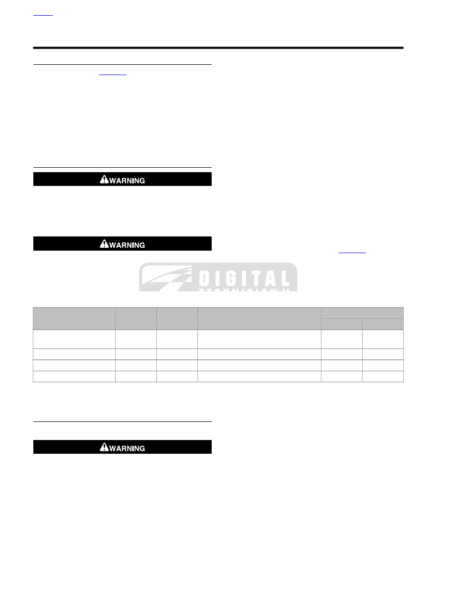
Use only tires listed in

Table 1-7

.

ABS equipped motorcycles must always use tires and wheels
that are the same as the original equipment. The ABS system
monitors rotational speed of the wheels through individual
wheel speed sensors to determine the application of ABS.
Changing to different diameter wheels or different size tires
can alter the rotational speed and upset the calibration of the
ABS, resulting in an adverse effect on its ability to detect and
prevent lockups. Tire inflation pressure that is significantly low
can also have an adverse effect.

TIRES

Match tires, tubes, rim seals, air valves and caps to the
correct wheel rim. Contact a Harley-Davidson dealer. Mis-
matching can result in damage to the tire bead, allow tire
slippage on the rim or cause tire failure, which could result
in death or serious injury. (00023b)

Use only Harley-Davidson approved tires. See a Harley-
Davidson dealer. Using non-approved tires can adversely
affect stability, which could result in death or serious
injury. (00024a)

NOTES

Tubeless tires are used on all Harley-Davidson cast and
disc wheels.

Tire sizes are molded on the tire sidewall. Inner tube sizes
are printed on the tube.

New tires should be stored on a horizontal tire rack. Avoid
stacking new tires in a vertical stack. The weight of the
stack compresses the tires and closes down the beads.

Check tire pressure and tread:

As part of the pre-ride inspection.

At every scheduled service interval.

1.

Inspect each tire for punctures, cuts and breaks.

2.

Inspect each tire for wear. Replace tires before they reach
the tread wear indicator bars.

NOTE

Missing indicator wear bars represent less than 1/32 in. (0.8
mm) tread pattern depth remaining.

3.

Check for proper front and rear tire pressures when tires
are cold. Compare results against

Table 1-7

.

Table 1-7. Tires

PRESSURE (COLD)

APPROVED TIRE

SIZE

MOUNT

MODEL

kPa

PSI

248

36

Dunlop D408F 130/80B17 65H

17 in.

front

All models except FLHRC,
FLTRX, FLHX

248

36

Dunlop D408F 130/90B16 67H

16 in.

front

FLHRC

248

36

Dunlop D408F 130/70B18 63H

18 in.

front

FLTRX, FLHX

276

40

Dunlop D407 180/65B16

16 in.

rear

All models

TIRE REPLACEMENT

Inspection

Harley-Davidson tires are equipped with wear bars that
run horizontally across the tread. When wear bars become
visible and only 1/32 in. (0.8 mm) tread depth remains,
replace tire immediately. Using a worn tire can adversely
affect stability and handling, which could result in death
or serious injury. Use only Harley-Davidson approved
replacement tires. (00090b)

Arrows on tire sidewalls pinpoint location of wear bar indicators.

Tread wear indicator bars will appear on tire tread surfaces
when 1/32 in (0.8 mm) or less of tire tread remains. Always
replace tires before the tread wear indicator bars appear.

When To Replace Tires

New

tires are needed if any of the following conditions exist:

1.

Tread wear indicator bars become visible on the tread
surfaces.

2.

Tire cords or fabric become visible through cracked side-
walls, snags or deep cuts.

3.

A bump, bulge or split in the tire.

4.

Puncture, cut or other damage to the tire that cannot be
repaired.

HOME

1-20 2011 Touring Service: Maintenance

When installing tires on rims, do not rely on tread design to
determine direction of rotation. Always be sure the rotational
arrows molded into the sidewalls point in the direction of rota-
tion when the vehicle is moving forward.

Refer to

Table 1-7

for approved tires.

Use only Harley-Davidson approved tires. See a Harley-
Davidson dealer. Using non-approved tires can adversely
affect stability, which could result in death or serious
injury. (00024a)

WHEEL BEARINGS

Service wheel bearings:

1.

Check wheel bearings as outlined in

2.10 SEALED

WHEEL BEARINGS

Replace wheel bearings if end play

exceeds 0.002 in. (0.051 mm).

2.

If wheel is already removed, check wheel bearings as fol-
lows:

a.

See

Figure 1-6

Insert finger into wheel bearing and

rotate the inner race in both directions. Repeat step
on opposite side of wheel.

b.

Replace the wheel bearings if there is drag, rough
rotation, abnormal noise or anything unusual.

3.

Check axle spacers for wear and corrosion. Replace as
necessary.

sm04767

Figure 1-6. Inspect Wheel Bearings

WHEEL SPOKES

TOOL NAME

PART NUMBER

SPOKE TORQUE WRENCH

HD-48985

SPOKE NIPPLE WRENCH

HD-94681-80

Spokes that are too tight can draw nipples through the rim
or distort hub flanges. Spokes that are too loose can
continue to loosen when put in service. Either condition
can adversely affect stability and handling, which could
result in death or serious injury. (00286a)

Do not over tighten spoke nipples. Protruding spoke
nipples can damage tube, resulting in rapid tire deflation,
which could cause death or serious injury. (00526d)

When lifting a motorcycle using a jack, be sure jack con-
tacts both lower frame tubes where down tubes and lower
frame tubes converge. Never lift by jacking on cross-
members, oil pan or other housings. Failure to comply can
cause serious damage resulting in the need to perform
major repair work. (00586c)

Identify Wheel Spoke Groups

NOTE

Spokes are grouped in sets of four.

1.

Raise wheel with a suitable lifting device.

2.

See

Figure 1-7

. Starting at the valve stem, identify the first

group of four spokes (1-4).

3.

Using a different color for each spoke in the group, draw
an alignment mark across the spoke nipple and onto the
rim.

4.

Continue around the wheel marking the rest of the spokes
the same as they were marked in the previous step.

Wheel Spoke Adjustment

NOTES

Do not tighten spoke more than 1/4 turn past alignment
mark. If more tension is needed, label spoke and check
after completing rest of wheel.

Do not use the torque spoke wrench to loosen spokes.
Use SPOKE NIPPLE WRENCH (Part No. HD-94681-80)
to loosen spokes.

1.

See

Figure 1-7

. Starting with the first group of spokes,

loosen spoke (1) using SPOKE NIPPLE WRENCH (Part
No. HD-94681-80) 1/4 turn.

HOME

2011 Touring Service: Maintenance 1-21

2.

Using SPOKE TORQUE WRENCH (Part No. HD-48985)
tighten spoke (1) to the value listed in

Table 1-8

.

a.

While tightening, if the torque wrench clicks before
the alignment marks align, continue to turn the spoke
nipple until the marks align.

b.

If the alignment marks align and the torque specifica-
tion has not been reached, continue to tighten the
spoke nipple until the correct torque is achieved, but
do not turn spoke nipple more then 1/4 turn past
alignment mark.

3.

Repeat previous two steps for spoke (4) in the same group.

4.

Continue around the wheel checking spokes 1 and 4 until
all groups are done.

5.

Repeat procedure for spokes (2, 3) in each group.

NOTE

When checking any spokes that were labeled, make sure to
use the original alignment mark.

6.

Check spokes, if any, that were labeled as not reaching
the proper torque value after tightening 1/4 turn past
alignment mark.

a.

Loosen spoke 1/4 turn past original alignment mark
using SPOKE NIPPLE WRENCH (Part No. HD-94681-
80).

b.

While tightening, if the torque wrench clicks before
the alignment marks align, continue to turn the spoke
nipple until the marks align.

c.

If the alignment marks align and the torque specifica-
tion has not been reached, continue to tighten the
spoke nipple until the correct torque is achieved, but
do not turn spoke nipple more then 1/4 turn past
alignment mark.

7.

True the wheel. See

2.9 CHECKING AND TRUING

WHEELS

.

Table 1-8. Spoke Nipple Torque Specification

MINIMUM TORQUE

RIM TYPE

55

in-lbs

(6.2 Nm)

All

1

3

2

4

sm06507

Figure 1-7. Tightening Laced Wheels (typical)

HOME

1-22 2011 Touring Service: Maintenance

1.9

PRIMARY CHAINCASE LUBRICANT

GENERAL

All models have an automatic chain tensioner. For primary
chain service procedures, see

5.4 DRIVE COMPONENTS

.

CHANGING PRIMARY CHAINCASE
LUBRICANT

1.

Run motorcycle until engine is warmed up to normal
operating temperature.

When draining or adding lubricant, do not allow dirt, debris
or other contaminants to enter the engine. (00198a)

Be sure that no lubricants or fluids get on tires, wheels or
brakes when changing fluid. Traction can be adversely
affected, which could result in loss of control of the
motorcycle and death or serious injury. (00047d)

2.

See

Figure 1-8

. Remove magnetic drain plug at bottom

of primary chaincase. Drain lubricant into suitable con-
tainer.

NOTE

Dispose of lubricant in accordance with local regulations.

3.

Clean drain plug. If plug has accumulated a lot of debris,
inspect the condition of chaincase components.

4.

Install

new

O-ring on drain plug.

5.

Install drain plug back into primary chaincase cover.
Tighten plug to 14-21 ft-lbs (19.0-28.5 Nm).

6.

See

Figure 1-9

. Remove five TORX screws with captive

washers (3) to detach clutch inspection cover (2) from
primary chaincase cover.

7.

Remove the seal (1). Wipe oil from groove in chaincase
cover and mounting surface.

Do not overfill the primary chaincase with lubricant.
Overfilling can cause rough clutch engagement, incomplete
disengagement, clutch drag and/or difficulty in finding
neutral at engine idle. (00199b)

8.

Refer to

Table 1-9

. Pour the specified amount of GENUINE

Harley-Davidson FORMULA+ TRANSMISSION AND
PRIMARY CHAINCASE LUBRICANT (Part No. 99851-05,
quart) in through the clutch inspection cover opening.

Table 1-9. Primary Chaincase Lubricant Refill Capacity

CAPACITY

ITEM

38 oz (1.12 L) wet

Primary chaincase lubricant

45 oz (1.33 L) dry

om00114a

Figure 1-8. Removal/Installation of Chaincase Drain Plug

3

2

1

om00709

1. Seal
2. Clutch inspection cover
3. Screws with captive washer

Figure 1-9. Clutch Cover

HOME

2011 Touring Service: Maintenance 1-23

Mainshaft

Wear safety glasses or goggles when removing or
installing retaining rings. Retaining rings can slip from the
pliers and could be propelled with enough force to cause
serious eye injury. (00312a)

NOTE

As mainshaft 4th gear, 3rd gear, 2nd gear and 1st gear are an
integral part of the shaft, damage to any gear requires main-
shaft replacement.

1.

See

Figure 6-15

. Using TRANSMISSION SHAFT

RETAINING RING PLIERS (Part No. J-5586A), remove
retaining ring. Remove dog ring (3), guiding hub (2),
mainshaft 5th gear (4) and bearing.

NOTE

Do not press directly on the end of the mainshaft. Place a
spacer such as a washer between the end of the mainshaft
and the press ram.

2.

Place transmission assembly in arbor press and press
mainshaft out of side door bearings.

4

1

3

2

sm03599a

1. Retaining ring pliers
2. Guiding hub
3. Dog ring
4. Mainshaft 5th gear

Figure 6-15. Mainshaft Retaining Ring

HOME

2011 Touring Service: Transmission 6-11

22

36

1

2

3

29

30

31

32

34

35

37

38

34

33

39

28

27

23

24

25

26

4

5

8

13

19

18

20

17

14

7

9

6

10

12

15

11

16

21

sm03019a

27.

14.

1.

Mainshaft 2nd gear

Bearing

Spacer

2.

28.

15.

Countershaft 1st gear

Mainshaft 1st gear

Lock ring

16.

3.

29.

Securing segment (2)

Bearing

Mainshaft 5th gear

30.

17.

4.

Dog ring

Dog ring

Dog ring

5.

31.

18.

Lock ring

Guiding hub

Guiding hub

19.

6.

32.

Countershaft 4th gear

Securing segment (2)

Retaining ring

33.

20.

7.

Retaining ring

Bearing

Guiding hub

8.

34.

21.

Countershaft 2nd gear

Main drive gear bearing (2)

Countershaft 5th gear (part of
countershaft)

9.

35.

Bearing

Main drive gear

22.

36.

Countershaft 6th gear (part of
countershaft)

10.

O-ring

Lock ring

11.

37.

Securing segment (2)

Bearing spacer

23.

38.

Mainshaft

12.

Retaining ring

Internal spline washer

13.

39.

24.

Countershaft 3rd gear

Oil seal

Bearing

25. Mainshaft 4th gear
26. Mainshaft 3rd gear

Figure 6-16. Mainshaft and Countershaft Assembly

HOME

6-12 2011 Touring Service: Transmission

9.

Install clutch inspection cover and

new

seal as follows:

a.

Thoroughly wipe all lubricant from cover mounting
surface and groove in chaincase.

b.

See

Figure 1-9

Position

new

seal (1) in groove in

clutch inspection cover and press each of the nubs
on seal into the groove. The nubs will retain seal in
position.

c.

See

Figure 1-10

. Insert screw (with captive washer)

through clutch inspection cover and carefully thread
it into the top cover screw hole.

d.

Start the remaining four screws (with captive
washers).

e.

Alternately tighten screws to 84-108

in-lbs

(9.5-12.2

Nm) following torque sequence shown in

Figure 1-10

.

4

5

2

3

1

sm02844

Figure 1-10. Clutch Cover Torque Sequence

HOME

1-24 2011 Touring Service: Maintenance

1.10

TRANSMISSION LUBRICANT

TRANSMISSION LUBRICATION

General

The transmission lubricant level should be checked monthly.

Refer to

Table 1-4

. The transmission should be drained and

refilled with fresh lubricant at specified intervals.

NOTE

When checking the transmission lubricant level, the motorcycle
should be leaning on the jiffy stand. If the motorcycle was
recently moved or ridden, allow a short period of time to
equalize lubricant level in the transmission compartments.

Check Lubricant Level

1.

Park motorcycle on its jiffy stand.

2.

See

Figure 1-11

Remove the filler plug/dipstick and wipe

off dipstick.

3.

See

Figure 1-12

. Place back in filler hole but do not thread

in. (Filler plug/dipstick should rest on top of threaded hole.)
Remove filler plug/dipstick and observe lubricant level.
Level should be between the full and low marks on the
dipstick.

Be sure that no lubricants or fluids get on tires, wheels or
brakes when changing fluid. Traction can be adversely
affected, which could result in loss of control of the
motorcycle and death or serious injury. (00047d)

When draining or adding lubricant, do not allow dirt, debris
or other contaminants to enter the engine. (00198a)

4.

Add the recommended GENUINE Harley-Davidson lub-
ricant as necessary. Refer to

Table 1-10

Do not overfill

or leakage may occur. The transmission fluid capacity is
approximately 32 fluid ounces (0.95 liters).

5.

Inspect O-ring for tears or damage. Replace if required.
Wipe any foreign material from plug.

6.

Install filler plug/dipstick and tighten to 25-75

in-lbs

(2.8-

8.5 Nm).

Table 1-10. Recommended Lubricant

LUBRICANT

MODEL

FORMULA+ TRANSMISSION AND

PRIMARY CHAIN LUBRICANT

(Part No. 99851-05)

or

SYN3 20W50 OIL

(Part No. 99824-03/00QT quart)

All

sm05694

Figure 1-11. Transmission Filler Plug/Dipstick Location

1

2

sm05327

1. FULL
2. ADD

Figure 1-12. Transmission Filler Plug/Dipstick Lubricant

Level

Changing Transmission Fluid

1.

See

Figure 1-11

Remove the threaded filler plug/dipstick.

HOME

2011 Touring Service: Maintenance 1-25

When draining or adding lubricant, do not allow dirt, debris
or other contaminants to enter the engine. (00198a)

Be sure that no lubricants or fluids get on tires, wheels or
brakes when changing fluid. Traction can be adversely
affected, which could result in loss of control of the
motorcycle and death or serious injury. (00047d)

2.

See

Figure 1-3

. Remove transmission drain plug (1) and

drain lubricant into a suitable container.

NOTE

Dispose of transmission lubricant in accordance with local
regulations.

3.

Inspect the drain plug O-ring for tears or damage. Replace
if required. Wipe any foreign material from plug.

4.

Install drain plug and tighten to 14-21 ft-lbs (19.0-28.5
Nm). Fill the transmission with 32 fl. oz. (0.95 liters) of the
recommended GENUINE Harley-Davidson lubricant. Refer
to

Table 1-10

.

NOTE

Do not overfill or leakage may occur. The transmission fluid
capacity is approximately 32 fl. oz. (0.95 liters).

5.

Install filler plug/dipstick and tighten to 25-75

in-lbs

(2.8-

8.5 Nm).

6.

Start engine and carefully check for oil leaks around drain
plug.

HOME

1-26 2011 Touring Service: Maintenance

1.11

CLUTCH

ADJUSTMENT

NOTE

Perform the clutch adjustment with the motorcycle at room
temperature. The clearance at the adjuster screw will increase
as the powertrain temperature increases. If adjuster screw is
adjusted with powertrain hot, clearance at push rod bearing
could be insufficient with powertrain cold and clutch slippage
could occur.

1.

Stand motorcycle upright and level.

2.

Remove clutch inspection cover from primary chaincase
cover.

3.

Remove seal ring from clutch inspection cover and discard.

4.

See

Figure 1-13

. Add freeplay to cable.

a.

Slide rubber boot (1) off cable adjuster.

b.

Loosen jam nut (3) and back away from cable
adjuster.

c.

Move adjuster (2) toward jam nut to introduce a large
amount of free play at hand lever.

5.

See

Figure 1-14

Loosen jam nut (1) on clutch adjuster

screw. Turn adjuster screw (2) inward (clockwise) until
lightly seated.

6.

Back out adjuster screw 1/2 to 1 full turn. While holding
adjuster screw, tighten jam nut to 72-120

in-lbs

(8.1-13.6

Nm).

7.

Squeeze clutch lever to maximum limit three times to set
ball and ramp release mechanism.

8.

See

Figure 1-13

. Check freeplay.

a.

Turn cable adjuster (2) away from jam nut (3) until
slack is eliminated at hand lever.

b.

See

Figure 1-15

. Pull clutch cable ferrule (2) away

from clutch lever bracket to check free play. Turn
cable adjuster as necessary to obtain 1/16-1/8 in.
(1.6-3.2 mm) free play between end of cable ferrule
and clutch lever bracket.

9.

Hold adjuster and tighten jam nut to 120

in-lbs

(13.6 Nm).

Cover cable adjuster mechanism with rubber boot.

10. Swab all lubricant from seal ring groove in clutch inspection

cover. Install

new

seal ring in groove with nubs contacting

ring groove walls.

11. Fasten clutch inspection cover to primary chaincase cover.

Alternately tighten screws to 84-108

in-lbs

(9.5-12.2 Nm)

in the sequence shown in

Figure 1-10

.

4

3

2

1

sm02219

1. Rubber boot
2. Cable adjuster
3. Jamnut
4. Cable end

Figure 1-13. Clutch Cable Adjuster

1

2

sm04769

1. Jam nut
2. Clutch adjuster screw

Figure 1-14. Clutch Adjuster Screw

HOME

2011 Touring Service: Maintenance 1-27


Content      ..     4      5      6      7     ..