Harley Davidson 2011 Touring Models. Service Manual - page 5
 

  Главная      Harley Davidson     Harley Davidson 2011 Touring Models. Service Manual


Search            copyright infringement  


Content      ..     3      4      5      6     ..


Harley Davidson 2011 Touring Models. Service Manual - page 5


CHANGING OIL AND OIL FILTER

TOOL NAME

PART NUMBER

OIL FILTER WRENCH

HD-42311

OIL FILTER WRENCH

HD-44067A

Refer to

Table 1-4

Oil should be changed after the first 1000

miles (1600 kilometers) for a

new

engine and at regular inter-

vals in normal service at warm or moderate temperatures.

Oil change intervals should be more frequent in cold weather
or severe operating conditions. See

1.3 FUEL AND OIL, Winter

Lubrication

.

Twin Cam equipped vehicles require the premium oil filter (Part
No. 63798-99A Chrome or Part No. 63731-99A Black).

Do not switch lubricant brands indiscriminately because
some lubricants interact chemically when mixed. Use of
inferior lubricants can damage the engine. (00184a)

Be sure that no lubricants or fluids get on tires, wheels or
brakes when changing fluid. Traction can be adversely
affected, which could result in loss of control of the
motorcycle and death or serious injury. (00047d)

1.

Ride motorcycle until oil is at normal operating temper-
ature. Turn engine off.

2.

Remove filler plug/dipstick.

3.

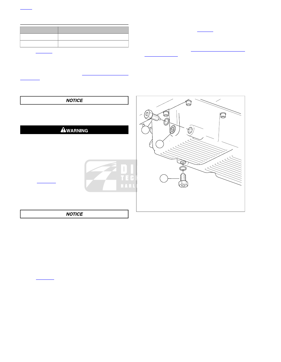
See

Figure 1-3

Remove the oil drain plug (2). Do not

remove hex plug (3) or transmission drain plug (1). Allow
oil to drain completely.

4.

Inspect the oil drain plug O-ring for cuts, tears or signs of
deterioration. Replace as necessary.

Use Harley-Davidson oil filter wrench for filter removal.
This tool can prevent damage to crankshaft position sensor
and/or sensor cable. (00192b)

5.

Remove the oil filter using OIL FILTER WRENCH (Part
No. HD-42311) or OIL FILTER WRENCH (Part No. HD-
44067A) and hand tools. Do not use with air tools.

6.

Clean the oil filter mount flange of any old gasket material.

NOTE

Dispose of oil and oil filter in accordance with local regulations.

7.

See

Figure 1-4

Lubricate gasket with clean engine oil and

install

new

oil filter on filter mount. Hand-tighten oil filter

one-half to three-quarters of a turn after gasket first con-
tacts filter mounting surface. Do NOT use oil filter wrench
for installation.

8.

Install engine oil drain plug and tighten to 14-21 ft-lb (19.0-
28.5 Nm).

NOTE

Use the proper grade of oil for the lowest temperature expected
before the next oil change. Refer to

Table 1-2

for recommended

oil.

9.

Initially add 3.5 quarts (3.3 liters) of engine oil.

10. Verify proper oil level. See

1.6 ENGINE OIL AND FILTER,

Checking Oil Level

.

a.

Check engine oil level using

COLD CHECK

pro-

cedure.

b.

Start engine and carefully check for oil leaks around
drain plug and oil filter.

c.

Check engine oil level using

HOT CHECK

procedure.

1

3

2

om00311

1. Transmission drain plug (right side)
2. Engine oil drain plug and O-ring
3. Hex plug (do not remove)

Figure 1-3. Oil Pan

HOME

1-16 2011 Touring Service: Maintenance

2

3

1

om00108a

1. Thin film of oil ONLY
2. Oil filter
3. Mounting plate

Figure 1-4. Applying Thin Oil Film

HOME

2011 Touring Service: Maintenance 1-17

1.7

AIR CLEANER AND EXHAUST SYSTEM

REMOVAL

1.

See

Figure 1-5

. Remove screw (1) and air cleaner cover

with rubber seal (3).

2.

Remove three screws (4) to release cover bracket (5) from
filter element.

3.

Remove filter element (6) pulling two breather tubes (8)
from holes on inboard side.

4.

Remove and discard gasket (7).

5.

Remove breather tubes from breather bolts.

6.

Inspect the breather tubes and rubber seal for cuts, tears,
holes or signs of deterioration. Replace as necessary.

Do not use gasoline or solvents to clean filter element.
Flammable cleaning agents can cause an intake system
fire, which could result in death or serious injury. (00101a)

Compressed air can pierce the skin and flying debris from
compressed air could cause serious eye injury. Wear
safety glasses when working with compressed air. Never
use your hand to check for air leaks or to determine air
flow rates. (00061a)

7.

Clean filter element.

a.

Wash the paper/wire mesh filter element (and breather
tubes) in lukewarm water with a mild detergent. Do
not strike filter element on a hard surface to dislodge
dirt.

b.

Allow filter element to either air dry or blow it dry, from
the inside, with low pressure air. Do NOT use air
cleaner filter oil on the Harley-Davidson paper/wire
mesh air filter element.

c.

Hold the filter element up to a strong light source. The
element is sufficiently clean if light is uniformly visible
through the media.

d.

Replace the filter element if damaged or if filter media
cannot be adequately cleaned.

2

1

3

5

4

6

7

8

sm04764

1. Cover screw
2. Air cleaner cover
3. Rubber seal
4. Cover bracket screw (3)
5. Cover bracket
6. Filter element
7. Gasket
8. Breather tube (2)

Figure 1-5. Air Cleaner Assembly

INSTALLATION

1.

Install

new

gasket (7) on air filter element.

2.

Insert breather tubes into holes on inboard side of filter
element approximately 0.25 in (6.4 mm).

NOTE

Air cleaner mounting without installation of the breather tubes
will allow crankcase vapors to be vented into the atmosphere
in violation of legal emissions standards.

3.

Install breather tubes onto breather bolts.

4.

Place filter element onto backplate with the flat side down.

5.

Install cover bracket and tighten screws (4) to 108-132

in-

lbs

(12.2-14.9 Nm).

6.

Verify that rubber seal is properly seated around perimeter
of air cleaner cover.

7.

Fit air cleaner cover into backplate. Apply a small dab of
LOCTITE MEDIUM STRENGTH THREADLOCKER 243
(BLUE) to threads of cover screw. Install screw and tighten
to 36-60

in-lbs

(4.1-6.8 Nm).

EXHAUST SYSTEM LEAK CHECK

Check the exhaust system for leaks at every scheduled service
interval as follows:

HOME

1-18 2011 Touring Service: Maintenance

1.

Check entire exhaust system for loose or missing
fasteners, broken pipe clamps or brackets, and obvious
signs of leakage (carbon tracks at pipe joints, etc.).

2.

Check for loose or broken heat shields. Repair or replace
as necessary.

3.

Start engine, cover muffler ends with clean, dry shop
towels and listen for audible signs of exhaust leakage.

4.

Correct any leaks detected. See

4.19 EXHAUST SYSTEM

for exhaust system removal and installation procedures.

HOME

2011 Touring Service: Maintenance 1-19

CLEANING AND INSPECTION

1.

See

Figure 6-6

. Wash the ball and ramp mechanism

components in cleaning solvent.

2.

Inspect the three balls (2) and ball socket surfaces on
ramps (1, 3) for wear, pitting, surface breakdown and other
damage. Replace damaged parts.

3.

Check fit of the ramp coupling (4) on inner ramp (1).
Replace both parts if there is excessive wear.

4.

Inspect the retaining ring (6) for damage or distortion.

5.

Check clutch cable end for frayed or worn ends. Replace
cable if damaged or worn. Check cable fitting O-ring for
cuts, tears or signs of deterioration.

6.

Check the bore in the cover (5) where the ramps (1, 3)
are retained. There should be no wear that would cause
the ramps to cock, causing improper clutch adjustment.

1

6

7

4

8

5

2

3

sm03010

1. Inner ramp
2. Balls (3)
3. Outer ramp
4. Ramp coupling
5. Clutch release cover
6. Retaining ring
7. Gasket
8. Tab

Figure 6-6. Release Mechanism Assembly

ASSEMBLY AND INSTALLATION

NOTE

Replace cable fitting O-ring if damaged or deformed.

1.

See

Figure 6-4

Apply a drop of Loctite Threadlocker 243

(blue) to the clutch cable fitting (1) and install into clutch
release cover. Do not tighten at this time.

2.

See

Figure 6-6

Place outer ramp (3) with ball socket side

up in clutch release cover. Be sure tab (8) is in clutch
release cover slot.

3.

Apply a multi-purpose grease to the balls and outer ramp
sockets. Place a ball in each of the outer ramp sockets.

4.

See

Figure 6-4

. Connect cable end to ramp coupling (3).

Install coupling on inner ramp (5) and place inner ramp
and coupling in position in clutch release cover.

Wear safety glasses or goggles when removing or
installing retaining rings. Retaining rings can slip from the
pliers and could be propelled with enough force to cause
serious eye injury. (00312a)

NOTE

Retaining ring opening (6) must be centered above the break
in the ribbing at bottom of the clutch release cover.

5.

Install retaining ring (4).

6.

Verify that two dowel pins are in place on transmission
side door flange. Place a

new

gasket on dowel pins.

NOTE

See

Figure 6-3

Clutch release cover screws in positions (1)

and (6) are shorter than the others.

7.

See

Figure 6-3

. Install clutch release cover. Tighten screws

to 90-120

in-lbs

(10.2-13.6 Nm) in sequence shown.

8.

Tighten clutch cable fitting to 90-120

in-lbs

(10.2-13.6

Nm).

9.

Fill transmission to proper level with fresh transmission
fluid. See

1.10 TRANSMISSION LUBRICANT, Transmis-

sion Lubrication

.

10. Adjust clutch cable. See

1.11 CLUTCH

.

11. Install exhaust system if removed. See

4.19 EXHAUST

SYSTEM

.

12. Install main fuse.

HOME

2011 Touring Service: Transmission 6-7

6.6

TRANSMISSION ASSEMBLY

REMOVAL

NOTE

Leave the transmission case in the frame unless the case itself
requires replacement. For illustration purposes, some photo-
graphs may show the case removed. For information on case
removal see

6.8 TRANSMISSION CASE

.

1.

Remove exhaust system. See

4.19 EXHAUST SYSTEM

.

2.

Relieve drive belt tension. See

1.12 DRIVE BELT AND

SPROCKETS

.

3.

Remove primary chaincase cover, clutch assembly,
primary chain, compensating sprocket assembly and
primary chaincase. See

5.5 PRIMARY CHAINCASE

HOUSING, Removal

.

4.

Remove the bearing inner race from the transmission
mainshaft. See

5.5 PRIMARY CHAINCASE HOUSING,

Mainshaft Bearing Inner Race

.

5.

Remove the clutch release cover from the transmission
side door. See

6.5 CLUTCH RELEASE COVER, Removal

and Disassembly

.

6.

See

Figure 6-7

Remove oil slinger assembly from main-

shaft. Insert long rod through mainshaft bore and remove
push rod.

7.

Remove transmission top cover, leaving the cover gasket
in place.

8.

See

Figure 6-8

. Rotate the shifter pawl forward enough

to raise the free end and place shifter cam pawl on top
cover gasket.

4

1

3

5

6

2

sm03013

1. Retaining ring
2. Thrust washer (2)
3. Throw out bearing
4. Oil slinger
5. Push rod
6. Push rod end, left side

Figure 6-7. Push Rod Assembly

2

1

sm03011

1. Shifter pawl
2. Top cover gasket surface

Figure 6-8. Set Shifter Pawl on Gasket

NOTES

Remove and install sprocket nut only while transmission
is in vehicle frame. Trying to remove and install sprocket
nut with transmission in transmission stand may cause
damage to transmission or stand.

The main drive gear bearing and retainer must be replaced
if the main drive gear is removed. The bearing will be
damaged during the removal procedure.

9.

If main drive gear is to be removed, see

6.7 MAIN DRIVE

GEAR AND BEARING, Removal

.

10. Cover mainshaft clutch hub splines with tape to prevent

the splines damaging the main drive gear bearings.

11. See

Figure 6-10

Remove the transmission side door

mounting hardware. Remove exhaust bracket, if equipped.

NOTE

See

Figure 6-9

Never attempt to remove side door by tapping

on shafts from opposite side. Tapping them with a hammer will
damage the side door bearings. If the side door sticks or binds
on the ring dowels, pry open using indents at each side of side
door.

12. Pry the side door loose and remove side door, mainshaft,

countershaft and shifter cam from transmission case as
an assembly. Discard gasket.

HOME

6-8 2011 Touring Service: Transmission

sm05040

Figure 6-9. Side Door Pry Point

2

2

2

1

sm03669

1. Long screw (2)
2. Short screw (6)

Figure 6-10. Side Door hardware

DISASSEMBLY

TOOL NAME

PART NUMBER

TRANSMISSION SHAFT RETAINING
RING PLIERS

J-5586A

Shifter Cam/Shifter Forks

1.

See

Figure 6-11

. With side door on end (shafts pointing

upward), remove shift fork shafts using easy-out screw
extractor (14) (non-flute design) or vise grips. Shafts have
slight interference fit. Shafts can be reused, do not damage
end of shaft. Mark end of shaft so same end can be rein-
serted during reassembly.

NOTE

Shifter shafts have a slight interference fit. Shifter shafts can
be reused, so avoid damaging end of shaft. Mark shafts so
they can be reinstalled in original position during assembly.

2.

Remove shift forks from dog rings.

3.

See

Figure 6-12

. Remove lock plate fasteners (3) from

lock plate (2). Discard fasteners.

4.

See

Figure 6-13

. Insert screwdriver and gently pry back

detent arm (4) to remove detent spring (3) tension from
shift cam (5). Remove shift cam.

5.

If servicing detent assembly, remove detent screw (2),
detent arm (4), sleeve and detent spring (3). Discard detent
screw.

NOTE

Although many transmission parts can be installed in either
direction, make sure used parts are installed in same direction
as when removed to prolong usable life.

6.

See

Figure 6-14

Using dog rings, lock two gears in place.

Temporarily place transmission assembly into transmission
case.

7.

Remove mainshaft and countershaft locknuts.

8.

Remove transmission assembly from transmission case.

3

4

5

6

7

1

2

13

14

12

11

10

9

8

sm05070a

1. Mainshaft
2. Countershaft
3. Mainshaft 1st gear
4. Mainshaft 2nd gear
5. Mainshaft 3rd gear
6. Mainshaft 4th gear
7. Mainshaft 5th gear
8. Countershaft 1st gear
9. Countershaft 2nd gear
10. Countershaft 3rd gear
11. Countershaft 4th gear
12. Countershaft 5th gear
13. Countershaft 6th gear
14. Screw extractor

Figure 6-11. Gear Set

HOME

2011 Touring Service: Transmission 6-9


Content      ..     3      4      5      6     ..