Harley Davidson Softail 2000-2005. Service manual - page 40
 

  Главная      Harley Davidson     Harley Davidson Softail 2000-2005. Service manual


Search            copyright infringement  


Content      ..     38      39      40      41     ..


Harley Davidson Softail 2000-2005. Service manual - page 40


4. On exhaust valve guides only

,

install the collar onto

the valve guide as follows:

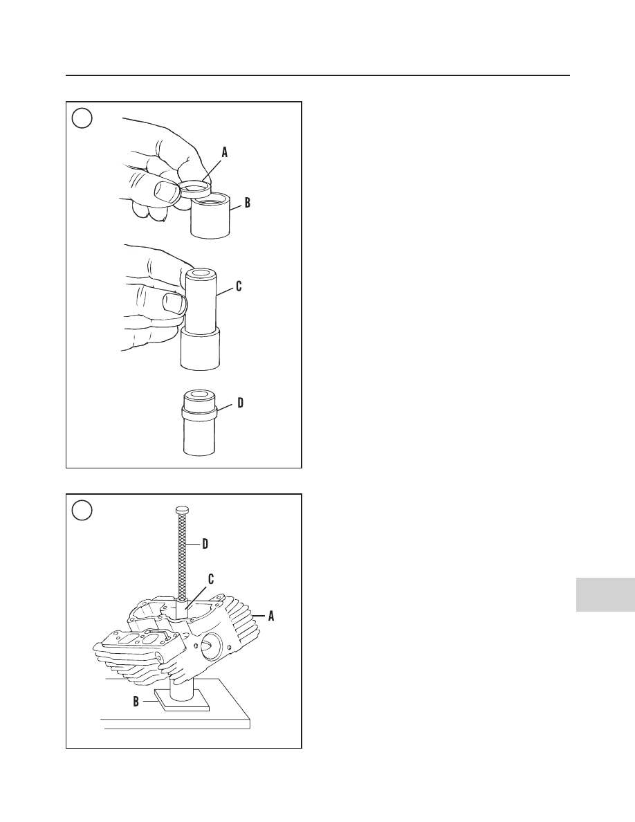
a. Insert the valve guide collar (A, Figure 30) onto the

installer sleeve (B) and center it squarely onto the
counter bore of the installer sleeve.

b. Install the

new

valve guide (C, Figure 30) into the

installer sleeve (B) until it contacts the valve guide
collar.

c. Install the installer sleeve and valve guide onto the

press table and center it.

d. Slowly apply pressure and drive the valve guide

onto the collar until the valve guide bottoms in the
installer sleeve.

e. Remove the valve guide/collar assembly (D, Figure

30) from the installer sleeve.

5. Apply a thin coat of Vaseline to the entire outer surface
of the valve guide before installing it in the cylinder head.

CAUTION

When installing oversize valve guides, make
sure to match each guide to its respective
bore in the cylinder head.

6. Install the

new

valve guide as follows:

a. Install the intake (A, Figure 28) or exhaust (B)

valve seat adapter into the tube at the top of the sup-
port stand (C).

b. Install the support stand on the hydraulic press ta-

ble.

c. Install the cylinder head (A, Figure 31) onto the

support stand (B)

centering

the cylinder head valve

seat onto the seat adapter.

d. On exhaust valves, position the valve guide with the

collar end going in last. The intake valve guides are
non-directional, either end can go in first.

e. Install the valve guide onto the cylinder head recep-

tacle.

f. Install the valve guide installer sleeve (C, Figure

31) over the valve guide, and insert the tapered end
of the valve guide driver (D) into the installer
sleeve.

g. Center the valve guide driver under the press ram

and make sure the driver is perpendicular to the
press table.

h. Support the cylinder head, slowly apply pressure

and slowly start to drive the valve guide into the cyl-
inder head receptacle. Stop and back off the press
ram to allow the valve guide to center itself.

i. Verify that the support stand (B, Figure 31) and

valve guide driver (D) are square with the press ta-
ble.

j. Once again apply press pressure and continue to

drive the valve guide part way into the cylinder

2004-2005 MODEL SERVICE INFORMATION

549

15

30

31

head receptacle. Once again, stop and back off the
press ram to allow the valve guide to center itself.

k. Again apply press pressure and continue to drive

the valve guide into the cylinder head receptacle un-
til the installer sleeve (C, Figure 31) contacts the
machined surface of the cylinder head.

l. Remove the cylinder head and special tools from

the press bed.

m. Repeat sub-steps a-k for the remaining valve

guides.

7. Replacement valve guides are sold with a smaller in-
side diameter than the valve stem. Ream the guide to fit
the valve stem as follows:

a. Apply a liberal amount of reamer lubricant to the

ream bit and to the valve guide bore.

b. Start the reamer straight into the valve guide bore.

CAUTION

Only apply pressure to the end of the drive
socket. If pressure is applied to the T-han-
dle, the bore will be uneven, rough cut and
tapered.

c. Apply thumb pressure to the end of the drive socket

portion of the T-handle while rotating the T-handle
clockwise

.

Only

light

pressure is required. Apply

additional lubricant to the reamer and into the valve
guide while rotating the reamer

.

d. Continue to rotate the reamer until the entire bit has

traveled through the valve guide and the shank of
the reamer rotates freely.

CAUTION

Never back the reamer out through the valve
guide as the guide will be damaged.

e. Remove the T-handle from the reamer. Remove the

reamer from the combustion chamber side of the
cylinder head.

f. Apply low-pressure compressed air to remove the

small shavings from the valve guide bore. Then
clean the valve guide bore with the small spiral
brush.

8. Hone the valve guide as follows:

a. Install the valve guide hone into a high-speed elec-

tric drill.

b. Lubricate the valve guide bore and hone stones with

the reamer lubricant–do not use engine oil

.

c. Carefully insert the hone stones into the valve guide

bore.

d. Start the drill and move the hone back and forth in

the valve guide bore for 10 to 12 complete strokes to
obtain a 60

°

crosshatch pattern.

9. Repeat Steps 7 and 8 for each valve guide.
10. Soak the cylinder head in a container filled with hot,
soapy water. Then clean the valve guides with a valve
guide brush or an equivalent bristle brush. Do not use a
steel brush. Do not use cleaning solvent, kerosene or gaso-
line as these chemicals will not remove all of the abrasive
particles produced during the honing operation. Repeat this
step until all of the valve guides are thoroughly cleaned.
Then rinse the cylinder head and valve guides in clear, cold
water and dry them with compressed air.
11. After cleaning and drying the valve guides, apply
clean engine oil to the guides to prevent rust.
12. Resurface the valve seats.

PISTONS AND PISTON RINGS

Piston Pin Bushing in Connecting Rod
Inspection and Replacement
(FSXTDSE2 and FLSTFSE Models)

The upper end of the connecting rod is tapered (Figure

32).

The piston pin bushing cannot be replaced on these mod-

els. If worn or damaged, replace or rebuild the crankshaft as-
sembly.

CRANKCASE AND CRANKSHAFT

Crankshaft Left Side Main Bearing
Assembly Inner Race Replacement

Removal

1. Remove the crankshaft assembly as described in Chap-
ter Four.

550

SUPPLEMENT

32

2. Support the crankshaft in a support fixture (part No.
HD- 44358 or an equivalent), with the bearing side facing
up (A, Figure 33).

3. Place a hardened plug (B, Figure 33) between the bear-
ing puller and the end of the crankshaft.

4. Install the bearing splitter under the bearing inner race
(C, Figure 33).

5. Apply graphite lubricant to the bearing puller center
screw, and attach a bearing puller (D, Figure 33) to the
splitter.

WARNING

In Step 6,

never

use a heat gun and penetrat-

ing oil at the same time. The heat from the
gun may ignite the oil.

6A. Use a heat gun and apply heat uniformly to the bear-
ing inner race for approximately 30 seconds.

6B. If a heat gun is not available, apply penetrating oil to
the inner race and crankshaft and allow the oil to penetrate
for 30 minutes.

7. Make sure the bearing puller is square to the crank-
shaft so the bearing inner race is not out of alignment with
the crankshaft shoulder.

8. Slowly tighten the center screw (E, Figure 33) and
withdraw the bearing inner race (F) from the crankshaft
shoulder.

9. Remove the bearing puller, splitter and bearing inner
race from the crankshaft.

10. Remove the thrust washer from the crankshaft. Dis-
card the thrust washer, it cannot be re-used.

11. Clean the sprocket shaft with contact cleaner. Check
the sprocket shaft for cracks or other damage. If it is dam-
aged, refer service to a Harley-Davidson dealership.

Installation

The sprocket shaft bearing cone installer (part No. HD-

997225-55B) is required to install the sprocket shaft bear-
ing inner race.

1. Support the crankshaft in a support fixture (part No.
HD- 44358 or an equivalent), with the bearing side facing
up (A, Figure 34).

2. Thread the pilot shaft (B, Figure 34) onto the crank-
shaft until it contacts the crankshaft

3. Slide the

new

thrust washer (C, Figure 34) over the

sprocket shaft.

WARNING

In Step 4,

never

use a heat gun and penetrat-

ing oil at the same time. The heat from the
gun may ignite the oil.

2004-2005 MODEL SERVICE INFORMATION

551

15

33

34

4A. Place the new bearing race on the workbench. Use
heat gun and uniformly heat the bearing race for approxi-
mately 60 seconds. Wear heavy duty gloves and install the
new inner race (D, Figure 34) onto the crankshaft
4B. If a heat gun is not available, apply penetrating oil to
the inner surface of the bearing race and to the crankshaft
shoulder. Install the

new

inner race (D, Figure 34) onto

the crankshaft.
5. Apply graphite lubricant to the threads of the pilot
shaft and flat washer
6. Slide the sleeve (E, Figure 34) onto the crankshaft un-
til it contacts the bearing inner race.
7. Slide the Nice bearing (F, Figure 34) and flat washer
(G) over the pilot shaft until it contacts the top of the sleeve.
8. Thread the handle (H, Figure 34) onto the pilot shaft
(B).

9. Slowly tighten the handle

clockwise

until the bearing

inner race bottoms on the crankshaft shoulder.
10. Unscrew and remove all parts of the special tool.
11. Install the crankshaft assembly as described in Chap-
ter Four.

COUNTER BALANCER ASSEMBLY

(FLSTFSE MODELS)

Removal/Installation

The removal and installation procedures are identical to

all prior models, including the 2004 FXSTDSE2 models.
Except for the addition of the outer thrust washer (6, Fig-
ure 35
) between the spacer and the roller bearing on
FLSTFSE models.

552

SUPPLEMENT

35

BALANCER SHAFT BEARING AND RACE

(2005 FLSTFSE MODELS)

1. Nut
2. Washer
3. Sprocket
4. Spacer
5. Bolt
6. Thrust washer–outer
7. Roller bearing
8. Balancer shaft support
9. Bearing inner race

10. Thrust washer–inner
11. Balancer

Balancers

Both balancers on these models are identified with a

shallow drilled hole as shown in A, Figure 36. Do not in-
terchange these balancers with other models and years.

The sprocket end of the balancer is equipped with a

thrust washer (B, Figure 36) and bearing inner race (C).
The bearing inner race is used in conjunction with the bal-
ancer shaft support roller bearing. All other Softail mod-
els covered in this manual are equipped with a ball bearing.

Bearing Race Removal/Installation

NOTE

This is only necessary if the balancer shaft
support roller bearing is replaced.

1. Remove the balancer as described in this supplement
and Chapter Four.

2. Remove the inner race (C, Figure 36) and inner thrust
washer (B). Discard the inner race as it cannot be reused
after it has been removed.

3. Clean the balancer shaft in solvent and dry with com-
pressed air.

4. Apply engine oil to the shaft and to the inner surface of
the bearing race.

5. Position the inner thrust washer with the chamfer side
going on first and install the inner thrust washer (B, Fig-
ure 36
).

6. Slide the bearing inner race onto the shaft as far as it
will go.

7. Install the outer thrust washer, sprocket spacer,
sprocket and the washer onto the shaft.

8. Thread the nut onto the shaft. If there are insufficient
exposed shaft threads, remove the spacer between the
thrust washers.

9. Secure the balancer in a vice equipped with soft jaws.

10. Slowly tighten the nut and press the inner race onto
the balancer shaft. Tighten the nut until the bearing inner
race is securely against the inner thrust washer. There
must be no space between the nut, the inner thrust washer
and the balancer shaft machined surface. Continue to
tighten the nut if necessary.

11. Remove the nut, washer, sprocket and outer thrust
washer from the shaft.)

2004-2005 MODEL SERVICE INFORMATION

553

15

36

Table 9 GENERAL ENGINE SPECIFICATIONS

Item

Specification

Engine type

Four-stroke, 45° OHV V twin
Twin Cam 88B, 95B and 103B (balanced)

Bore and Stroke

88B models

3.75 × 4.00 in. (95.25 × 101.6 mm)

95B models

3.875 × 4.00 in. (98.425 × 101.6 mm)

103B models

3.875 × 4.375 in. (98.425 × 111.125 mm)

Displacement

88B models

88 cubic inch (1450 cc)

95B models

95 cubic inch (1550 cc)

103B models

103 cubic inch (1690 cc)

Compression ratio

88B and 103B models

9.0:1

95B models

9.2:1

(continued)

Table 9 GENERAL ENGINE SPECIFICATIONS (continued)

Item

Specification

Torque

88B models

82 ft. lb. (111 N•m) @ 3000 rpm

95B models

91 ft. lb. (123 N•m) @ 3500 rpm

103B models

FXSTDSE2

91 ft. lb. (123 N•m) @ 3500 rpm

FLSTFSE

100 ft. lb. (138 N•m) @ 3500 rpm

Maximum sustained engine speed

88B models

5600 rpm

95B and 103B models

5500 rpm

Engine and transmission weight

204 lbs. (92.5 kg)

Cooling system

Air cooled

Table 10 ENGINE SERVICE SPECIFICATIONS (88B ENGINE)

New

Service limit

Item

in. (mm)

in. (mm)

Valve stem-to-guide clearance (2005 models)

Intake

0.001-0.003 (0.0254-0.0762)

0.0038 (0.0965)

Exhaust

0.001-0.003 (0.0254-0.0762)

0.0038 (0.0965)

Valve seat width (2005 models)

Intake and exhaust

0.040-0.062 (1.02-1.58)

Valve stem protrusion (2005 models)

Intake and exhaust

2.005-2.039 (50.93-51.79)

Valve spring free length (2005 models)

Intake and exhaust

2.325 (59.1)

Camshaft support plate

Camshaft chain tensioner

Shoe

0.090 (2.29)*

Crankshaft bushing fit

0.0008 (0.0203)

Crankshaft bushing inside diameter

0.8545 (21.704)

Valve lifters

Roller fit

0.015 (0.38)

Roller end clearance

0.015 (0.38)

* 1/2 thickness of shoe.

Table 11 ENGINE SERVICE SPECIFICATIONS (95B ENGINE)

New

Service limit

Item

in. (mm)

in. (mm)

Cylinder bore

Standard

3.875 (98.4)

Oversize 0.005 in.

3.880 (98.56)

Cylinder bore (continued)

Oversize 0.010 in.

3.885 (98.68)

Oversize 0.020 in.*

3.895 (98.93)

Oversize 0.030 in.*

3.905 (99.19)

Cylinder

Taper

0.002 (0.05)

Out of round

0.003 (0.08)

Warp

At top (cylinder head)

0.006 (0.15)

At base (crankcase)

0.008 (0.20)

Piston-to-cylinder clearance

0.0053 (0.135)

(continued)

554

SUPPLEMENT

Table 11 ENGINE SERVICE SPECIFICATIONS (95B ENGINE) (continued)

New

Service limit

Item

in. (mm)

in. (mm)

Piston pin clearance in piston

0.001 (0.025)

Piston rings

Compression ring end gap

Top ring

0.012-0.022 (0.30-0.56)

0.030 (0.762)

Second ring

0.015-0.025 (0.38-0.635)

0.034 (0.863)

Oil control ring

0.010-0.050 (0.25-1.27)

0.050 (1.27)

Compression ring side clearance

Top ring

0.0012-0.0037 (0.030-0.094)

0.0045 (0.11)

Second ring

0.0012-0.0037 (0.030-0.094)

0.0045 (0.11)

Oil control ring

0.0012-0.0037 (0.030-0.094)

0.0045 (0.11)

Valve stem-to-guide clearance

Intake

0.0015-0.0033 (0.038-0.084)

0.0038 (0.0965)

Exhaust

0.0008-0.0026 (0.020-0.066)

0.0038 (0.0965)

Valve seat width

Intake and exhaust

0.040-0.062 (1.02-1.58)

Valve stem protrusion

Intake and exhaust

2.005-2.039 (50.93-51.79)

Valve spring free length

Intake and exhaust

2.325 (59.1)

Camshaft support plate

Camshaft chain tensioner

Shoe

0.090 (2.29)*

Crankshaft bushing fit

0.0008 (0.0203)

Crankshaft bushing

inside diameter

0.8545 (21.704)

Connecting rod

Connecting rod-to-crankpin clearance

0.00043-0.0017 (0.0109-0.0432)

0.002 (0.05)

Piston pin clearance in connecting rod

0.0003-0.0007 (0.008-0.018)

0.001 (0.025)

Crankshaft

Runout (flywheel at rim)

0.000-0.010 (0.000-0.25)

0.015 (0.38)

Runout (shaft at flywheel)

0.000-0.002 (0.000-0.05)

0.003 (0.08)

End play

0.001-0.005 (0.03-0.13)

0.006 (0.15)

Valve lifters

Roller fit

0.015 (0.38)

Roller end clearance

0.015 (0.38)

* 1/2 thickness of shoe.

Table 12 ENGINE SERVICE SPECIFICATIONS (103B ENGINE)

New

Service limit

Item

in. (mm)

in. (mm)

Cylinder bore

Standard

3.877 (98.48)

Oversize 0.005 in.

3.882 (98.60)

Cylinder bore (continued)

Oversize 0.010 in.

3.887 (98.73)

Oversize 0.020 in.*

3.895 (98.93)

Oversize 0.030 in.*

3.905 (99.19)

Piston-to-cylinder clearance

0.003 (0.076)

Piston pin clearance in piston

0.0008 (0.020)

Piston rings (2004 model)

Compression ring end gap

Top ring

0.012-0.022 (0.30-0.56)

0.032 (0.81)

Second ring

0.015-0.025 (0.38-0.635)

0.035 (0.89)

Oil control ring end gap

0.010-0.050 (0.25-1.27)

0.050 (1.27)

(continued)

2004-2005 MODEL SERVICE INFORMATION

555

15

Table 12 ENGINE SERVICE SPECIFICATIONS (103B ENGINE) (continued)

New

Service limit

Item

in. (mm)

in. (mm)

Compression ring side clearance

Top ring

0.0012-0.0037 (0.030-0.094)

0.0045 (0.11)

Second ring

0.0012-0.0037 (0.030-0.094)

0.0045 (0.11)

Oil control ring end gap

0.0012-0.0072 (0.030-0.18)

0.010 (0.25)

Piston rings (2005 model)

Compression ring end gap

Top ring

0.012-0.022 (0.30-0.56)

0.030 (0.762)

Second ring

0.015-0.025 (0.38-0.635)

0.034 (0.863)

Oil control ring

0.010-0.050 (0.25-1.27)

0.050 (1.27)

Compression ring side clearance

Top ring

0.0012-0.0037 (0.030-0.094)

0.0045 (0.11)

Second ring

0.0012-0.0037 (0.030-0.094)

0.0045 (0.11)

Oil control ring

0.0012-0.0072 (0.030-0.18)

0.010 (0.25)

* Oversize 0.020 in. and 0.030 in. available on 2004 models only.

Table 13 ENGINE TORQUE SPECIFICATIONS

ft.-lb.

in.-lb.

N•m

Cylinder head bolts

Refer to text

Chrome trim cap

60-84

7-9

CHAPTER FIVE

CLUTCH AND PRIMARY DRIVE

CLUTCH ASSEMBLY

(2005 MODELS)

The clutch assembly is identical to prior years with the ex-

ception of the seal on the clutch inspection cover. The O-ring
has been replaced with a large gasket. Install the

new

gasket

as follows:

1. Position the new gasket with the rubber molding and
the words TOWARD ENGINE facing away from the
clutch inspection cover.

2. Align the triangular shaped hole in the

new

gasket with

the top hole in the clutch inspection cover.

CAUTION

Do not push the screw through the triangular
shaped hole in the new gasket as the sealing
qualities of the gasket will be damaged.

3. Insert the screw, with the captive washer, through the
clutch inspection cover and carefully thread it it all the way
through the triangular shaped hole in the new gasket.

4. Install the clutch inspection cover and new gasket onto the
clutch inspection cover and thread the top screw part way in.

5. Make sure the clutch inspection cover is correctly aligned
with the chaincase cover and install the remaining four
screws with captive washers.

6. Use a T27 Torx driver and tighten the screws in a criss-
cross pattern to 84-108 in.-lb. (10-12 N•m).

556

SUPPLEMENT

CLUTCH ASSEMBLY

(FXSTDSE2 AND FLSTFSE MODELS)

The clutch release mechanism (Figure 37) is hydrauli-

cally operated. The system consists of a clutch master cylin-
der on the left side handlebar and a release cylinder on the
right side of the transmission case.

CLUTCH RELEASE BEARING AND PUSHROD

(FXSTDSE2 AND FLSTFSE MODELS)

On hydraulic clutch models, it is not necessary to

perform any procedure to allow slack on the dia-
phragm spring during the clutch assembly removal
procedure.

2004-2005 MODEL SERVICE INFORMATION

557

15

37

CLUTCH ASSEMBLY

(FXSTDSE2 AND FLSTFSE MODELS)

1. Snap ring
2. Clutch shell and sprocket
3. Bearing
4. Snap ring
5. Clutch hub
6. Clutch nut
7. Diaphragm spring seat
8. Diaphragm spring
9. Friction disc B

10. Clutch plates

11. Friction disc A
12. Pressure plate
13. Diaphragm spring
14. Diaphragm spring retainer
15. Bolt
16. Pushrod
17. Bearing
18. Release plate
19. Snap ring–small
20. Snap ring–large

Removal/Installation

NOTE

On models so equipped, always disarm the
optional TSSM security system prior to dis-
connecting the battery or the siren will sound.

NOTE

The clutch release bearing and pushrod can
be removed without removing the primary
chaincase outer cover.

1. Disconnect the battery negative cable as described in
Chapter Eight.
2. Remove the clutch mechanism inspection cover and
quad ring, or gasket.

CAUTION

Harley-Davidson specifies that a

new

quad

ring must be installed every time the
chaincase outer cover is removed.

3. Remove the screws securing the clutch inspection
cover. Remove the cover and the gasket.
4. Remove the large snap ring (A, Figure 38) securing
the release bearing plate.
5. Remove the release bearing plate (B, Figure 38) and
the pushrod (C) as an assembly.
6. If necessary, remove the small snap ring (D, Figure 38)
and remove the pushrod from the release bearing plate.
7. Measure the pushrod and release plate movement as
described in the following procedure.
8. Install by reversing the removal steps. Note the follow-
ing:

a. Make sure the snap rings seat correctly into their re-

spective grooves.

b. Install a new clutch inspection cover gasket as de-

scribed under

Clutch Assembly (2005 Models)

in

this section.

Pushrod and Release Plate Movement Inspection

CAUTION

Transmission gear changing will be difficult
or impossible if the correct amount of re-
lease movement is not maintained.

1. If still in place, remove the clutch mechanism inspec-
tion cover and quad ring, or gasket.
2. Mount a dial indicator onto the crankcase outer cover,
or onto a suitable stationary stand.
3. Position the dial indicator anvil against the end of the
pushrod (C, Figure 38).

4. Fully apply the clutch hand lever and note the pushrod
movement.
5. The pushrod must move a minimum of 0.065 in. (1.65
mm) for complete clutch disengagement.
6. If the pushrod movement is less than specified, the
clutch fluid level is low and/or the clutch system must be
bled. Bleed the clutch as described in this Supplement

.

7. Install the clutch inspection cover and quad ring or
gasket.

CLUTCH SERVICE

(FXSTDSE2 AND FLSTFSE MODELS)

The hydraulic clutch system transmits hydraulic pressure

from the master cylinder to the clutch release mechanism
on the transmission case. As the clutch components wear,
the clutch release piston moves out. As this occurs, the
fluid level in the master cylinder reservoir goes down. This
must be compensated for by occasionally adding fluid.

The proper operation of this system depends on a sup-

ply of clean brake fluid (DOT 5) and a clean work envi-
ronment when any service is being performed. Any debris
that enters the system can damage the components and
cause poor brake performance.

Brake fluid is hygroscopic (absorbs moisture) and

moisture in the system will reduce clutch performance.
Purchase brake fluid in small containers and properly dis-
card any small quantities that remain. Small quantities of
fluid will quickly absorb the moisture in the container.
Use only fluid clearly marked DOT 5. If possible, use the

558

SUPPLEMENT

38

same brand of fluid. It is not possible to remove all of the
old fluid. Other types are not compatible with DOT 5. Do
not reuse drained fluid and discard old fluid properly.

Perform clutch service procedures carefully. Do not use

any sharp tools inside the master cylinder or release mech-
anism. Damage of these components could cause a loss of
hydraulic pressure.

Consider the following when service the clutch system:

1. The hydraulic components rarely require disassembly.
Make sure it is necessary.
2. Keep the reservoir cover in place to prevent the entry
of moisture and debris.
3. Clean parts with an aerosol brake parts cleaner or
brake fluid. Never use petroleum-based solvents on inter-
nal clutch system components. They will cause seals to
swell and distort.
4. If the hydraulic system, not including the reservoir
cover, has been opened bleed the system to remove air
from the system. Refer to

Clutch System Bleeding

in this

Supplement.
5. Before performing any procedure in which there is the
possibility of brake fluid contacting the motorcycle, cover
the work area with a piece of plastic.
6. Before working on the clutch system, fill a bucket with
soap and water and keep it close to the motorcycle. If
brake fluid contacts the motorcycle, clean the area and
rinse it thoroughly.

CLUTCH MASTER CYLINDER

(FXSTDSE2 AND FLSTFSE MODELS)

Read the information listed under

Clutch Service

in this

Supplement before servicing the clutch master cylinder

.

Removal/Installation

1. Support the motorcycle on level ground on a swing
arm stand.
2. Block the front wheel so the motorcycle will not roll in
either direction while on the swing arm stand.
3. Cover the fuel tank and front fender with plastic to pro-
tect them from accidental brake fluid spills.
4. Drain the clutch master cylinder lever hose as de-
scribed under

Clutch System Flushing

in this Supplement.

5. Remove the banjo bolt and washers securing the clutch
hose to the master cylinder. Plug the clutch hose to prevent
brake fluid from dripping out. Tie the loose end of the hose
to the handlebar to prevent it from dripping brake fluid.
6. Plug the bolt opening in the master cylinder to prevent
leakage when removing the master cylinder in the follow-
ing steps.

7. Remove the master cylinder holder mounting bolts,
washers and the holder, and remove the clutch master cyl-
inder from the handlebar.
8. If necessary, service the master cylinder as described
in this section.
9. Clean the handlebar, master cylinder and clamp mating
surfaces.
10. Mount the master cylinder onto the handlebar and po-
sition it to rider’s preference.
11. Install the master cylinder holder and its mounting
bolts and washers.
12. Tighten the upper master cylinder clamp bolt first,
then the lower bolt. Tighten both bolts to 60-80 in.-lb.
(7-9 N•m).

NOTE

When the master cylinder clamp is correctly
installed, the upper edge of the clamp tou-
ches the master cylinder, leaving a gap at
the bottom.

13. Secure the clutch hose to the master cylinder with the
banjo bolt and two new washers on each side of the clutch
hose. Tighten the banjo bolt to 17-22 ft.-lb. (23-31 N•m).
14. Bleed the clutch as described under

Clutch System

Bleeding

in this Supplement

.

15. Test ride the motorcycle to ensure the clutch is oper-
ating correctly.

Disassembly

Refer to Figure 39.

1. Remove the master cylinder as described in this section.
2. If still in place, remove the master cylinder cover and
diaphragm. Pour out any remaining brake fluid and dis-
card it.
3. Remove the snap ring from hand lever pivot pin.
4. Slightly apply the hand lever to remove some of the
spring pressure on the pivot pin.
5. Withdraw the pivot pin from the body and remove the
clutch lever. Do not lose the bushing and roller kit from
the lever.
6. Remove the rubber boot from the groove in the body at
the end of the piston.
7. Remove the piston assembly and spring from the mas-
ter cylinder bore. Do not remove the primary and second-
ary cups from the piston.

NOTE

If brake fluid is leaking from the piston bore,
the piston cups are worn or damaged. Re-
place the piston assembly.

2004-2005 MODEL SERVICE INFORMATION

559

15

Assembly

1. If installing a new piston assembly, assemble it as de-
scribed under

Inspection

in this section.

2. Lubricate the piston (A, Figure 40), primary cup (B),
secondary cup (C), rubber boot (D) and cylinder bore with
DOT 5 brake fluid.

3. Position the spring (E, Figure 40) with the flange end
going in last and install the spring onto the piston.

CAUTION

Do not allow the piston cups to tear or turn
inside out when installing the piston into the
master cylinder bore. Both cups are larger
than the bore. To ease installation, lubricate
the cups and piston with DOT 5 brake fluid.

560

SUPPLEMENT

39

CLUTCH MASTER CYLINDER

(FXSTDSE2 AND FLSTFSE MODELS)

1. Screw
2. Top cover
3. Diaphragm
4. Sight glass
5. Bolt
6. Washer
7. Holder
8. Sealing washer
9. Hose

10. Banjo bolt
11. O-rng
12. Body
13. Snap ring
14. Bushing and roller kit
15. Hand lever
16. Bushing
17. Pivot pin
18. Piston assembly

40

4. Insert the spring and piston assembly into the master
cylinder bore. Push in on the piston and completely com-
press the spring until it is flush with the end of the body.

5. Hold the piston in place and carefully install the rubber
boot into the groove in the body. Make sure the entire per-
imeter of the boot is correctly seated around the groove.

CAUTION

The rubber boot must seat in the master cyl-
inder groove completely. Slowly push and
release the piston a few times to make sure it
moves smoothly and that the rubber boot
does not pop out.

6. Lubricate the pivot pin with silicone brake grease.

7. If removed, install the bushing and roller kit into the
end of the hand lever.

8. Install the hand lever onto the body and install the
pivot pin part way in from the top.

9. Slightly apply the hand lever to compress the spring
and push the piston in all the way.

10. Install a

new

snap ring into the pivot pin and make

sure it is correctly seated in the groove.

11. Check that the hand lever moves freely. If there is any
binding or roughness, remove the pivot pint and hand le-
ver and inspect the parts.

12. Temporarily install the diaphragm and cover. Install
the screws and tighten finger tight. Do not tighten the
screws, as brake fluid will be added later.

13. Install the master cylinder as described in this section.

Inspection

The manufacturer does not supply specifications for the

clutch master cylinder. Replace visually worn or damaged
parts as described in this section.
1. Clean and dry the master cylinder assembly as follows:

a. Use only DOT 5 brake fluid to wash rubber parts

(rubber boot and piston assembly) in the clutch sys-
tem. Never allow any petroleum-based cleaner to
contact the rubber parts. These chemicals cause the
rubber to swell, requiring their replacement.

b. Clean the master cylinder piston rubber boot groove

carefully. Use a small pick or brush to clean the
groove. If a hard varnish residue has built up in the
groove, soak the master cylinder in solvent to help
soften the residue. Then wash in soapy water and
rinse completely.

c. Blow the master cylinder dry with compressed air.
d. Place cleaned parts on a clean lint-free cloth until

assembly.

CAUTION

Do not get any oil or grease onto any of the
master cylinder components. These chemi-
cals cause the rubber parts in the brake sys-
tem to swell, permanently damaging them.

CAUTION

Do not remove the primary and secondary
cups from the piston assembly for cleaning
or inspection purposes.

2. Check the piston assembly (Figure 41) for the follow-
ing defects:

2004-2005 MODEL SERVICE INFORMATION

561

15

41

a. Check the piston (A, Figure 41) for scratches

and/or corrosion.

b. Worn, cracked, damaged or swollen primary (B,

Figure 41) and secondary cups (C).

c. Worn or damaged rubber boot (D, Figure 41).
d. Broken, distorted or collapsed piston return spring

(E, Figure 41).

e. Corroded, weak or damaged snap ring.
f. If any of these parts are worn or damaged, replace

the piston assembly.

3. To assemble a

new

piston assembly, perform the fol-

lowing:

a. If replacing the piston, install the new primary and

secondary cups onto the piston. Use the original
piston assembly as a reference when installing the
new cups onto the piston.

b. Before installing the new piston cups, lubricate

them with DOT 5 brake fluid.

c. Clean the new piston (A, Figure 41) in brake fluid.
d. Install the primary cup (B, Figure 41) onto the spring

and then the secondary (C) cup onto the piston.

4. Inspect the master cylinder bore. Replace the master
cylinder if its bore is corroded, cracked or damaged in any
way. Do not hone the master cylinder bore to remove
scratches or other damage.

5. Make sure the fluid passageway in the base of the body
is clear. Clean out with compressed air if necessary.

6. Check the banjo bolt threads for damage.

7. Inspect the diaphragm and cover for deterioration and
other damage.

8. Check the hand lever assembly for the following de-
fects:

a. Damaged hand lever.

b. Excessively worn or damaged pivot bolt.

c. Worn or damaged bushing.

CLUTCH RELEASE MECHANISM

(FXSTDSE2 AND FLSTFSE MODELS)

Release Mechanism Cover

Refer to Figure 42.

Removal

1. Support the motorcycle on level ground on a swing arm
stand.

2. Block the front wheel so the motorcycle will not roll in ei-
ther direction.

562

SUPPLEMENT

42

CLUTCH RELEASE MECHANISM

(FXSTDSE2 AND FLSTFSE MODELS)

1. Bolt
2. Cover
3. Bleed valve
4. Cap
5. Gasket

6. Spring
7. Primary cup
8. O-ring
9. Piston

3. Remove the front cylinder exhaust pipe as described in
Chapter Seven.
4. Drain the transmission oil as described in Chapter
Three.
5. Remove the transmission oil level dipstick.
6. Slightly loosen the bolts securing the cover and apply
the clutch lever. This will break the cover and gasket loose
from the transmission case.
7. Cover the frame under the transmission case with a
heavy cloth or plastic tarp to protect it from accidental
brake fluid spills.
8. Drain the clutch lever hose as described under

Clutch

System Bleeding

in this Supplement.

9. Carefully loosen the flare nut (A, Figure 43) securing the
clutch hose to the cover. Do not scratch the chrome cover.

10. Disconnect the clutch hose (B, Figure 43) from the
cover and place the end into a reclosable plastic bag. Re-
move the O-ring (Figure 44) from the end of the clutch hose,
or if necessary, remove the O-ring from within the cover
threaded outlet.

NOTE

There are two different length cover bolts,
note the location during removal.

11. Remove the bolts loosened in Step 6. Remove the cover
and gasket from the transmission case.
12. Remove the locating dowels if loose.

Installation

1. If removed, install the locating dowels.
2. Install a

new

gasket over the locating dowels.

3. Install the cover and the bolts in the correct location as
noted during removal. Tighten the bolts in a crisscross pat-
tern to 120-144 in.-lb. (14-16 N•m).
4. Install a

new

O-ring

(

Figure 44) onto the end of the

clutch hose.
5. Connect the clutch hose (B, Figure 43) onto the cover.
Thread the flare nut all the way into the cover by hand until it
bottoms. Do not cross-thread it and tighten to 80-115 in.-lb.
(9-13 N•m). Do not scratch the cover.
6. Install the transmission oil level dipstick.
7. Refill the transmission oil as described in Chapter
Three.
8. Install the front cylinder exhaust pipe as described in
Chapter Seven.
9. Refill the clutch master cylinder and bleed the system as
described under

Clutch System Bleeding

in this Supple-

ment.
10. Start the engine and check for proper clutch operation.

Release Cylinder

Removal/installation

1. Remove the release mechanism cover as described in this
section.
2. If removed, install the bleed valve (C, Figure 43) and
tighten securely.
3. To remove the piston, perform the following:

a. Place a piece of soft wood on the work bench.
b. Position the release cover with the piston side facing

toward the wood on the work bench.

c. Apply compressed air through the clutch hose hole in

the cover and force the piston part way out of the
cover receptacle.

2004-2005 MODEL SERVICE INFORMATION

563

15

43

44

4. Withdraw the piston assembly (Figure 45) and spring
from the cover receptacle.
5. If the primary cup was removed from the piston, install
the cup with the raised leading edge lip positioned toward
the spring receptacle end.
6. Apply DOT 5 brake fluid to the

new

primary cup, O-ring

and piston. Also apply DOT 5 brake fluid to the piston re-
ceptacle in the cover.
7. Install the spring into the piston and install the assembly
into the cover receptacle. Guide the primary cup into the re-
ceptacle to prevent the lips from turning over.
8. Push the piston and spring in until they bottom. Push in
on the piston and check that the spring pushes it back out part
way. The piston must move freely within the receptacle.
9. Install the release mechanism cover as described in this
section.

Inspection

Replacement parts are not available for the piston assem-

bly. If any part is worn or damaged, replace the piston and
spring as an assembly. Refer to Figure 46.
1. Clean the cover receptacle and piston in DOT 5 brake
fluid, or isopropyl alcohol and dry with compressed air.
2. Inspect the spring for fractures or sagging.
3. Check the O-ring and primary cup for hardness or deteri-
oration.
4. Check the piston and receptacle for scratches, scoring or
other damage.
5. Check the piston O-ring and primary cup grooves for
damage.
6. Inspect the flare nut threaded hole in the cover. If it is
worn or damaged, clean it out with a thread tap or replace the
cover.
7. Inspect the bleed valve threaded hole in the cover. If it is
worn or damaged, clean it out with a thread tap or replace the
cover.
8. Inspect the bleed screw. Apply compressed air to the
opening and make sure it is clear. Clean it out, if necessary,
with brake fluid. Install the bleed screw and tighten se-
curely.

CLUTCH HYDRAULIC HOSE REPLACEMENT

(FXSTDSE2 AND FLSTFSE MODELS)

1. Support the motorcycle on level ground on a swing arm
stand.
2. Block the front wheel so the motorcycle will not roll in ei-
ther direction.
3. Remove the front cylinder exhaust pipe as described in
Chapter Seven.

4. Cover the frame under the transmission case with a
heavy cloth or plastic tarp to protect it from accidental
brake fluid spills.
5. Drain the front clutch lever hose as described under

Clutch System Bleeding

in this Supplement.

6. Carefully loosen the flare nut (A, Figure 43) securing
the clutch hose to the cover. Do not scratch the chrome
cover.
7. Disconnect the clutch hose (B, Figure 43) from the
cover and place the end into a reclosable plastic bag. Re-
move the O-ring (Figure 44) from the end of the clutch
hose, or if necessary, remove the O-ring within the cover
threaded outlet.

564

SUPPLEMENT

46

CLUTCH RELEASE

CYLINDER (FXSTDSE2

AND FLSTFSE MODELS)

1. Piston
2. O-ring
3. Primary cup
4. Spring

45


Content      ..     38      39      40      41     ..