Harley Davidson Softail 2000-2005. Service manual - page 41
 

  Главная      Harley Davidson     Harley Davidson Softail 2000-2005. Service manual


Search            copyright infringement  


Content      ..     39      40      41      42     ..


Harley Davidson Softail 2000-2005. Service manual - page 41


8. Remove the banjo bolt and washers securing the clutch
hose to the master cylinder. Plug the clutch hose to pre-
vent brake fluid from dripping out.

9. Plug the bolt opening in the master cylinder to prevent
leakage and entry of debris.

10. On the left side frame down tube, remove the bracket
securing the clutch hose to the frame.

11. Remove the clutch hose from the frame and out from
behind the voltage regulator/rectifier and from the eyelet
on the right side of the crankcase behind the rear brake
master cylinder.

12. Install the

new

clutch hose through the frame follow-

ing the same path noted during removal.

13. Secure the clutch hose to the master cylinder with the
banjo bolt and two

new

washers on each side of the clutch

hose. Tighten the banjo bolt to 17-22 ft.-lb. (23-31 N•m).

14. Install a

new

O-ring (Figure 44) onto the end of the

clutch hose.

15. Connect the clutch hose (B, Figure 43) onto the
cover. Thread the flare nut all the way into the cover by
hand until it bottoms. Do not cross-thread it and tighten to
80-115 in.-lb. (9-13 N•m). Do not scratch the cover.

16. Bleed the clutch as described under

Clutch System

Bleeding

in this Supplement.

17. Test ride the motorcycle to ensure the clutch is oper-
ating correctly.

CLUTCH SYSTEM FLUSHING

(FXSTDSE2 AND FLSTFSE MODELS)

When flushing the clutch system, use DOT 5 brake

fluid as a flushing fluid. Flushing consists of pulling new
brake fluid through the clutch system until the new fluid
appears at the release cover bleed valve without the pres-
ence of any air bubbles. To flush the clutch system, follow
one of the bleeding procedures described under

Clutch

System Bleeding

in this Supplement.

CLUTCH SYSTEM BLEEDING

(FXSTDSE2 AND FLSTFSE MODELS)

Brake Bleeder Process

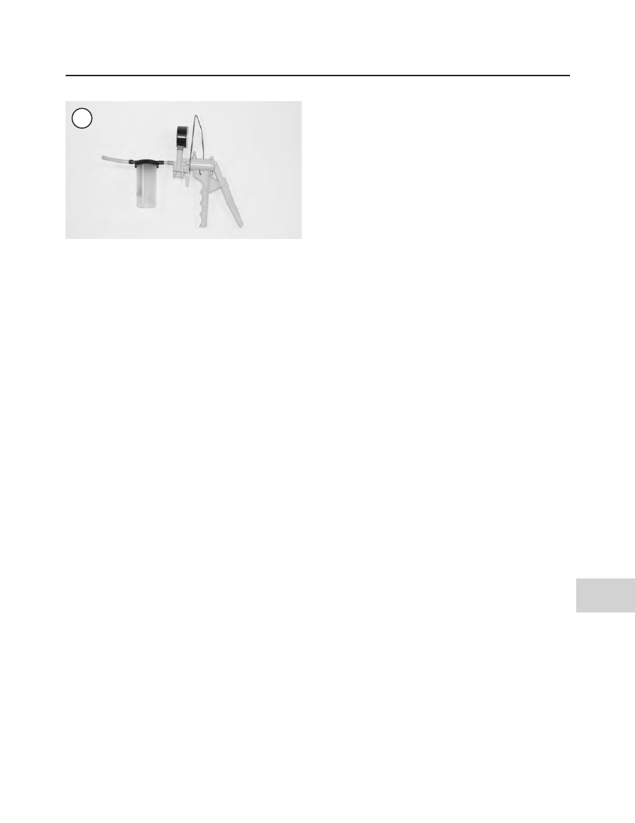
This procedure uses the Mityvac hydraulic brake bleed-

ing kit (Figure 47) that is available from automotive or
motorcycle supply stores.
1. Remove the dust cap from the bleed valve (C, Figure
43
) on the release cover.
2. Place a clean shop cloth over the exhaust pipe and
frame to protect it from accidental brake fluid spills.
3. Assemble the Mityvac tool according to its manufac-
turer’s instructions. Secure it to the bleed valve.
4. Open the bleed screw approximately a half turn.
5. Clean the top of the master cylinder of all debris.
6. Turn the handlebars to level the clutch master cylinder
and remove the screws, reservoir cover and diaphragm.
7. Fill the reservoir almost to the top with DOT 5 brake
fluid and reinstall the diaphragm and cover. Leave the
cover in place during this procedure to prevent entry of
debris.
8. Operate the pump several times to create a vacuum in
the line. Brake fluid will quickly draw from the release
cylinder into the pump’s reservoir. Tighten the release cyl-
inder bleed valve before the fluid stops flowing through
the hose. To prevent air from being drawn through the
master cylinder, add fluid to maintain its level at the top of
the reservoir.

NOTE

Do not allow the master cylinder reservoir
to empty during the bleeding operation or
more air will enter the system. If this occurs,
the procedure must be repeated.

9. Continue the bleeding process until the fluid drawn
from the release cylinder is bubble free. If bubbles are
withdrawn with the brake fluid, more air is trapped in the
line. Repeat Step 8, making sure to refill the master cylin-
der to prevent air from being drawn into the system.
10. When the brake fluid is free of bubbles, tighten the
bleed valve and remove the brake bleeder assembly. Rein-
stall the bleed valve dust cap.
11. If necessary, add fluid to correct the level in the mas-
ter cylinder reservoir. When topping off the clutch master
cylinder, turn the handlebar until the reservoir is level;
add fluid until it is level with the reservoir gasket surface.
The fluid level in the rear master cylinder must be slightly
below the upper gasket surface.
12. Reinstall the reservoir diaphragm and cover. Install
the screws and tighten securely.

2004-2005 MODEL SERVICE INFORMATION

565

15

47

13. Test the feel of the clutch lever. It must be firm and of-
fer the same resistance each time it’s operated. If it feels
spongy, it is likely that there is still air in the system and it
must be bleed again. After bleeding the system, check for
leaks and tighten all fittings and connections as necessary.

WARNING

Do not ride the motorcycle until the clutch
lever is operating correctly with full hy-
draulic advantage.

14. Test ride the motorcycle and make sure the clutch is
operating properly.

Without a Brake Bleeder

1. Remove the dust cap from the bleed valve (C, Figure
43
) from the release cover.
2. Connect a length of clear tubing to the bleed valve on
the release cover. Place the other end of the tube into a
clean container. Fill the container with enough fresh DOT
5 brake fluid to keep the end of the tube submerged. The
tube must be long enough so that a loop can be made
higher than the bleeder valve to prevent air from being
drawn into the caliper during bleeding.
3. Clean the top of the clutch master cylinder of all de-
bris.
4. Remove the screws securing the master cylinder top
cover and remove the cover and the diaphragm.
5. Fill the reservoir almost to the top with DOT 5 brake
fluid and reinstall the diaphragm and cover. Leave the
cover in place during this procedure to prevent entry of
debris.

NOTE

During this procedure, it is important to
check the fluid level in the master cylinder
reservoir often. If the reservoir runs dry,
more air will enter the system.

6. Slowly apply the clutch lever several times. Hold the
lever in the applied position and open the bleed valve

about 1/2 turn. Allow the lever to travel to its limit. When
the limit is reached, tighten the bleed valve, then release
the clutch lever. As the brake fluid enters the system, the
level will drop in the master cylinder reservoir. Maintain
the level at the top of the reservoir to prevent air from be-
ing drawn into the system.

7. Continue the bleeding process until the fluid emerging
from the hose is completely free of air bubbles. If the fluid
is being replaced, continue until the fluid emerging from
the hose is clean.

NOTE

If bleeding is difficult, allow the fluid to sta-
bilize for a few hours. Repeat the bleeding
procedure when the tiny bubbles in the sys-
tem settle out.

8. Hold the lever in the applied position and tighten the
bleed valve. Remove the bleed tube and install the bleed
valve dust cap.

9. If necessary, add fluid to correct the level in the master
cylinder reservoir. When topping off the front master cyl-
inder, turn the handlebar until the reservoir is level; add
fluid until it is level with the reservoir gasket surface.

10. Install the diaphragm and the top cover and tighten
the screws securely.

11. Test the feel of the clutch lever. It must be firm and of-
fer the same resistance each time it’s operated. If it feels
spongy, it is likely that there is still air in the system and it
must be bled again. After bleeding the system check for
leaks and tighten all fittings and connections as necessary.

WARNING

Do not ride the motorcycle until the clutch is
operating correctly with full hydraulic ad-
vantage.

12. Test ride the motorcycle and make sure the clutch is
operating properly.

Table 14 CLUTCH AND PRIMARY DRIVE TORQUE SPECIFICATIONS

ft.-lb.

in.-lb.

N•m

Clutch master cylinder

clamp bolts

60-80

7-9

Clutch cover

120-144

14-16

Clutch hose

at master cylinder

17-22

23-31

at cover

80-115-

9-13

Clutch inspection cover

84-108

10-12

566

SUPPLEMENT

CHAPTER SIX

TRANSMISSION

SHIFTER ASSEMBLY

(FXSTDSE2 AND FLSTFSE MODELS)

The shifter assembly (Figure 48) consists of the exter-

nal shift linkage and internal shift cam and shift arm com-
ponents. The internal components can be serviced with
the transmission case installed in the frame by removing
the top cover.

If a shift problem is encountered, refer to the trouble-

shooting procedures in Chapter Two and eliminate all
clutch and shifter mechanism possibilities

before

consid-

ering transmission repairs. Low clutch fluid level, or air in
the clutch hydraulic system can also cause poor shifting.

Shift Linkage Adjustment

The shift linkage assembly connects the transmission

shift rod lever to the foot-operated shift lever. The shift
linkage does not require adjustment unless it is replaced
or the transmission gears do not engage properly.

NOTE

On models so equipped, always disarm the
optional TSSM security system prior to dis-
connecting the battery or the siren will
sound.

1. Disconnect the negative battery cable as described in
Chapter Eight.
2. Loosen the two shift linkage rod locknuts (A, Figure
49
, typical).
3. Turn the shift linkage rod (B, Figure 49) as necessary
to change the linkage adjustment.
4. Tighten the locknuts to 80-120 in.-lb. (9-14 N•m).

5. Recheck the shifting. Readjust if necessary.
6. If this adjustment does not correct the shifting, check
the shift linkage for interference problems.

EXTERNAL SHIFT MECHANISM

(FXSTDSE2 AND FLSTFSE MODELS)

Removal/Installation

Refer to Figure 48.

NOTE

On models so equipped, always disarm the
optional TSSM security system prior to dis-
connecting the battery or the siren will
sound.

1. Disconnect the battery negative cable as described in
Chapter Eight.
2. Support the motorcycle with the front wheel off the
ground. See

Motorcycle Stands

in Chapter Eight.

3. Make an alignment mark on the outer shift lever and
the end of the shift shaft lever.
4. Remove the clamp bolt and remove the outer shift lever.
5. Remove the nylon washer from the inner shift lever.
6. Remove the acorn nut and washers (Figure 50, typi-
cal) securing the shift linkage rod to the outer shift lever.
7. Remove the jiffy stand and mounting bracket assembly
as described in Chapter Fourteen.
8. Remove the primary chaincase assembly as described
in Chapter Five.
9. Remove the acorn nut and washers securing the shift
shaft lever (Figure 51, typical) to the transmission case.

2004-2005 MODEL SERVICE INFORMATION

567

15

568

SUPPLEMENT

48

CLUTCH SHIFTER ASSEMBLY

(FXSTDSE2 AND FLSTSE MODELS)

1. Snap ring
2. Bearing
3. Bolt
4. Support–right side
5. Shift cam
6. Seal
7. Support–left side
8. Locating dowel
9. Sleeve

10. Cam follower
11. Spring
12. Bolt
13. Shift fork shaft
14. Shift fork No. 3
15. Shift fork No. 2

16. Shift fork No. 1
17. Set screw
18. Shift rod end
19. Bolt
20. Locknut
21. Shift rod
22. Acorn nut
23. Shift lever
24. O-ring
25. Bearing sleeve
26. Nylon washer
27. Screw
28. Lock washer
29. Outer shift lever
30. Insert

31. Screw
32. Shift lever peg
33. Cover
34. Spacer
35. Shift lever
36. Bolt
37. Snap ring
38. Oil seal
39. Washer
40. Centering pin
41. Transmission case
42. Shift lever centering pin
43. Shift shaft lever/pawl
44. Spring

10. Remove the shift rod, inner and outer shift lever as an
assembly.
11. Install by reversing these removal steps. Tighten the
clamp bolt securely.

TRANSMISSION SIDE DOOR AND

TRANSMISSION SHAFT ASSEMBLIES

(FXSTDSE2 and FLSTFSE Models)

The oil slinger assembly is not used on these models.

CHAPTER SEVEN

FUEL, EXHAUST AND EMISSION CONTROL SYSTEMS

AIR FILTER BACKPLATE

(FXSTDSE2, FLSTFSE AND

FLSTFI-15TH ANNIVERSARY)

Removal

Refer to Figures 52-54.

1. Remove the air filter cover screw and remove the
cover and gasket (models so equipped).

2A. On FXSTDSE2 models, remove the screws and
bracket from the air filter element.
2B. On FLSTFSE models, remove the screws and the
cover adapter from the air filter element.
2C. On FLSTFI-15th Anniversary models, remove the
screws from the air filter element.
3. Gently pull the air filter element from the back plate.
4. Gently pull the breather plugs from the breather screws
on the back plate.

2004-2005 MODEL SERVICE INFORMATION

569

15

Table 15 TRANSIMISSION TORQUE SPECIFICATIONS

ft.-lb.

in.-lb.

N•m

Shift rod locknuts

80-120

9-14

49

50

51

5A. On FXSTDSE2 models, use a deep socket and re-
move the breather screws securing the back plate. Pull the
back plate away from the cylinder heads and remove it.

5B. On FLSTFSE and FLSTFI-15th Anniversary models,
perform the following:

a. Use a deep socket and remove the breather screws

securing the back plate.

b. Use a deep socket and remove the mounting studs.

c. Pull the backplate away from the cylinder heads and

remove it.

6. Remove the gasket from the backside of the backplate
and discard it.

Inspection

1. Inspect the backplate for damage.

2. Make sure the breather screws and plugs are clear.
Clean them out if necessary.

570

SUPPLEMENT

52

AIR FILTER (2005 FLSTFI FAT BOY 15TH ANNIVERSARY MODELS)

1. Screw
2. Air filter
3. Baffle plug
4. Breather screw
5. Moutning stud
6. Backing plate
7. O-ring
8. Gasket
9. Screw

10. Trim ring
11. Cover

Installation

1. Install

new

O-rings in the grooves around the breather

screw holes.
2. Apply a couple dabs of gasket sealer to the

new

gasket

and install it onto the backside of the backplate. Make sure
it is aligned correctly with the bolt holes.
3. Move the backplate into position.
4A. On FXSTDSE2 models, install the breather screws
and tighten securely.

4B. On FLSTFSE and FLSTFI-15th Anniversary models,
perform the following:

a. Install the mounting studs and tighten to 55-60

in.-lb. (6-7 N•m).

b. Install the breather screws and tighten securely.

5. Install the breather plugs into the breather screws.

6. On FXSTDSE2 models, inspect the cover gasket. Re-
place it if necessary.

2004-2005 MODEL SERVICE INFORMATION

571

15

53

AIR FILTER (2004 FXSTDSE2 MODELS)

1. Screw
2. Mounting bracket
3. Air filter
4. Breather screw
5. Mounting stud
6. Backng plate
7. O-ring
8. Gasket
9. Label

10. Screw
11. Trim
12. Cover
13. Seal

NOTE

If an aftermarket air filter element is being in-

stalled, position it onto the back plate follow-

ing the manufacturer’s instructions.

7A. On FLSTFI-15th Anniversary models, move the ele-
ment into position and the screws. Tighten the screws se-
curely.

7B. On models other than FLSTFI-15th Anniversary mod-
els, move the element into position. Install the mounting
bracket (FXSTDSE2 models) or cover adapter (FLSTFSE
models) and the screws. Tighten the screws securely.

8. Apply a drop of low strength threadlocking compound to
the cover screw prior to installation.

9. Install the air filter cover and the screw. Tighten the screw
to 36-60 in.-lb. (4-7 N•m).

572

SUPPLEMENT

54

AIR FILTER (2005 FLSTFSE MODELS)

1. Screw
2. Cover adapter
3. Air filter
4. Breather plug
5. Breather screw
6. Mounting stud
7. Backing plate
8. O-ring
9. Gasket

10. Label
11. Screw
12. Trim ring
13. Cover

FUEL TANK CONSOLE

(FLSTFSE MODELS)

Removal/Installation

Refer to Figure 55.

NOTE

On models so equipped, always disarm the
optional TSSM security system prior to dis-

connecting the battery or the siren will
sound.

1. Disconnect the negative battery cable as described in
Chapter Eight.
2. Remove the seat as described in Chapter Fourteen.
3. Remove the acorn nut and washer securing the console to
the fuel tank.
4. Lift the console partially up off the fuel tank and lay it up-
side down on shop cloths or towels.

2004-2005 MODEL SERVICE INFORMATION

573

15

55

FUEL TANK CONSOLE

(FLSTFSE MODELS)

1. Trim bezel
2. Seal ring
3. Speedometer
4. Acorn nut
5. Washer
6. Rubber boot
7. Fuel tank console
8. Screw
9. Ignition switch

10. Bezel
11. Indicator lamp assembly
12. Mounting clamp
13. Trim panel
14. Bolt

5. Disconnect the 12-pin electrical connector from the
speedometer.

6. Disconnect the electrical connector from the indicator
lamp assembly and the ignition switch.

7. Remove the console and trim panel assembly.

8. Install by reversing these removal steps. Note the follow-
ing:

a. Make sure the trim panel is in place on the console.

b. Carefully position the console in place and carefully

route the electrical cables between the console and
fuel tank so they will not get pinched.

c. Turn the ignition switch on and make sure the indica-

tor lamps are illuminated.

d. Start the engine to make sure the ignition switch is

working. Turn off the engine.

FUEL TANK GAUGE

Removal/Installation

Refer to Figure 56 and Figure 57.

1. Remove the seat as described in Chapter Fourteen.

574

SUPPLEMENT

56

FUEL LEVEL SENDING UNIT

(2004-2005 FXSTD MODELS)

1. Screw
2. Clip
3. Connector
4. O-ring
5. Top plate
6. Clip

7. Fuel level gauge
8. O-ring
9. Gasket

10. Sending unit
11. Connector

2004-2005 MODEL SERVICE INFORMATION

575

15

57

FUEL LEVEL SENDING UNIT

(2004-2005 EXCEPT FXSTD MODELS)

1. Screw
2. Top plate
3. Connector
4. O-ring
5. Fuel level gauge
6. O-ring
7. Clip
8. Sending unit
9. Gasket

10. Connector

2. Disconnect the negative battery cable as described in
Chapter Eight.
3. Remove the fuel tank as described in Chapter Seven.

CAUTION

The fuel gauge sending unit electrical wires
are routed through a tube in the fuel tank
and are secured with a clamp at the bottom
of the fuel tank. Loosen the clamp (

Figure

58

) and make sure there is enough slack in

the wires to allow the gauge to be pulled up
and out of the fuel tank. Do not twist the fuel
gauge as the fuel gauge will be damaged.

4. To remove the fuel gauge only, perform the following:

a. Carefully pull straight up and partially withdraw the

fuel gauge from the fuel tank.

b. Mark the wire connectors and the terminal on the

fuel gauge to ensure correct installation.

c. Disconnect the electrical connectors from the back

of the fuel gauge. Do not disconnect the wires from
the sending unit.

d. Remove the fuel gauge and gasket. Discard the gas-

ket.

5. To remove the fuel gauge sending unit, perform the
following:

a. Remove the fuel gauge as described in Step 4.

b. Remove the Torx screws (A, Figure 59) securing

the top plate.

CAUTION

Do not bend the float arm during removal of
the sending unit. If bent, the gauge will give
inaccurate readings.

c. Carefully withdraw the top plate (B, Figure 59) and

sending unit while moving it back and forth, and
while lifting and turning it in either direction.

d. Remove the gasket from the fuel tank and discard it.

6. Install by reversing these removal steps. Note the follow-
ing:

NOTE

Do

not

apply any type of gasket sealer to the

top plate gasket.

a. Install

new

gaskets between the fuel gauge and fuel

tank.

b. Install the sending unit

carefully

to avoid damage to

the float arm.

c. Tighten all screws securely.

576

SUPPLEMENT

58

59

Table 16 FUEL SYSTEM TORQUE SPECIFICATIONS

ft.-lb.

in.-lb.

N•m

Air filter cover screw

36-60

4-7

Breather plate mounting studs

55-60

6-7

CHAPTER EIGHT

ELECTRICAL SYSTEM

STARTING SYSTEM

Starter Removal/Installation
(2005 Models)

The starter removal and installation procedure is the

same as on prior models with the exception of the starter
jackshaft bolt torque specification. Tighten the jackshaft
bolt to 60-80 in.-lb. (7-9 N•m). Bend the outer lockplate
tab against the bolt head.

Starter Disassembly/Assembly

The starter is the same as on previous models with the

exception of a trim cap on some models.
1. On models so equipped, remove the screw securing the
cover to the bracket. Remove the cover.
2. Remove the nuts securing the trim cover bracket to the
through bolts. Remove the bracket.
3. Install by reversing these disassembly steps. Tighten
the nuts and screw securely.

VOLTAGE REGULATOR

(FXSTDSE2 AND FLSTFSE MODELS)

Voltage Regulator
Removal/Installation

Refer to Figure 60.

1. Disconnect the negative battery cable as described in
Chapter Eight.
2. Remove the rear fender inner fender as described in
Chapter Fourteen.
3. Disconnect the voltage regulator lead (Figure 61)
from the silver post on the main circuit breaker.

NOTE

Prior to removing the voltage regulator
wires, note the routing of the wires through
the frame. Note the location of cable straps
and tie wraps. The wires must be rerouted in
the same path.

4A. On FXSTDSE2 models, perform the following:

2004-2005 MODEL SERVICE INFORMATION

577

15

60

CHARGING SYSTEM

COMPONENTS (FXSTDSE2

AND FLSTFSE MODELS)

1. Stator
2. Torx bolt
3. Rotor
4. Washer
5. Anchor connector
6. Ring terminal
7. Shrink tube--yellow
8. Mounting bracket (FXSTDSE2 models only)
9. Nut

10. Voltage regulator
11. Bolt

a. Remove the bolts securing the voltage regulator to

the mounting bracket.

b. Remove the front spoiler as described in this Sup-

plement.

c. Remove the screw securing the ground wire to the

mounting bracket.

d. Disconnect the voltage regulator multi-pin electri-

cal connector.

e. Follow the single electrical wire to the main circuit

breaker and cut the cable straps securing the lead to
the frame.

f. Carefully remove the single wire from the frame

and remove the voltage regulator and related wiring
from the frame

4B. On FLSTFSE models, perform the following:

a. Remove the front spoiler as described in this Sup-

plement.

b. Disconnect the voltage regulator multi-pin electri-

cal connector.

c. Remove the screw securing the ground wire to the

mounting bracket.

d. Remove the bolts securing the voltage regulator to

the frame cross member and remove the voltage
regulator.

5. Install by reversing these removal steps. Note the fol-
lowing:

a. Secure the ground strap to the mounting bracket.
b. Tighten the mounting nut or bolts securely.
c. Apply a light coat of dielectric compound to the

electrical connectors prior to installing them.

d. Install new cable straps and tie wraps securing elec-

trical wires to the frame.

LIGHTING SYSTEM

Headlight Bulb Replacement
(2005 FLSTC, FLSTF, FLSTN
and FXSTDSE2 Models)

Refer to Figure 62.

WARNING

If the headlight has just burned out or just
turned off, it will be hot. To avoid burned
fingers, allow the bulb to cool prior to re-
moval.

1. Remove the screw at the base of the trim bezel and re-
move the trim bezel from the headlight lens assembly.
2. Pull the lens assembly part way out of the headlight
case.
3. Pull

straight out

on the electrical connector and dis-

connect it from the bulb. Remove the headlight assembly.

4. Remove the connector boot (Figure 63) from the back
of the headlight lens. Check the rubber boot for tears or
deterioration; replace it if necessary.
5. Squeeze the light bulb retaining clip (Figure 64) and
pivot it out of the way.
6. Remove and discard the blown bulb (Figure 65).
7. Align the tangs on the new bulb with the notches in the
headlight lens and install the bulb.
8. Securely hook the retaining clip onto the bulb.
9. Install the connector boot and make sure it is correctly
seated against the bulb and the retainer.
10. Correctly align the electrical plug terminals with the
bulb and connect the plug. Push it

straight on

until it bot-

toms on the bulb and the connector boot.
11. Check headlight operation.
12. Insert the lens into the headlight housing and seat it
correctly.
13. Install the trim bezel and screw. Tighten the screw se-
curely.
14. Check headlight adjustment

Passing Light and Front Turn
Signal Bulb Replacement
(2005 FLSTN Models)

Refer to Figure 66.

1. Remove the passing light bulb as follows:

a. Loosen the clamping screw at the base of the trim

bezel and remove the trim bezel from the passing
light housing.

b. Carefully pull the sealed beam unit partially out of

the housing.

c. Loosen the two screws securing the wiring harness

(Figure 67) to the bulb/lens assembly and remove it.

d. Connect the wiring harness to the

new

sealed beam

unit and tighten the screws securely.

e. Install the ring over the edge of the sealed beam

unit. Rotate the ring so that the index tab engages
the slot at the bottom of the sealed beam unit.

578

SUPPLEMENT

61

f. Push the sealed beam unit into the housing and in-

stall the trim bezel.

g. Tighten the clamping screw securely.

2. Remove the front turn signal bulb as follows:

a. Locate the notch in the lens cap.

b. Insert a coin into the notch and carefully twist the

coin until the lens cap comes off the housing (A,
Figure 68).

c. Push in on the bulb (B, Figure 68), rotate it and re-

move it.

d. Install a new bulb and lens.

2004-2005 MODEL SERVICE INFORMATION

579

15

62

HEADLIGHT (2005 FLSTC, FLSTF, FLSTN

AND FXSTD MODELS)

1. Housing
2. Connector boot
3. Headlight bulb
4. Deflector
5. Headlight lens
6. Retaining ring

(FLSTC, FLSTF, FLSTN)*

7. Screw

8. Trim bezel
9. Bolt

10. Washer
11. Lockwasher
12. Nut
*Adapter ring for FXSTD, FTSTB

not shown

63

64

65

580

SUPPLEMENT

66

PASSING LAMPS AND FRONT TURN SIGNALS

(2005 FLSTN MODELS)

1. Washer
2. Bolt
3. Turn signal assembly
4. Mounting bracket
5. Collar
6. Turn signal bulb
7. Lens
8. Nut
9. Collar

10. Wiring
11. Sealed beam
12. Screw
13. Trim ring
14. Nut

67

68


Content      ..     39      40      41      42     ..