Harley Davidson Softail 2000-2005. Service manual - page 29
 

  Главная      Harley Davidson     Harley Davidson Softail 2000-2005. Service manual


Search            copyright infringement  


Content      ..     27      28      29      30     ..


Harley Davidson Softail 2000-2005. Service manual - page 29


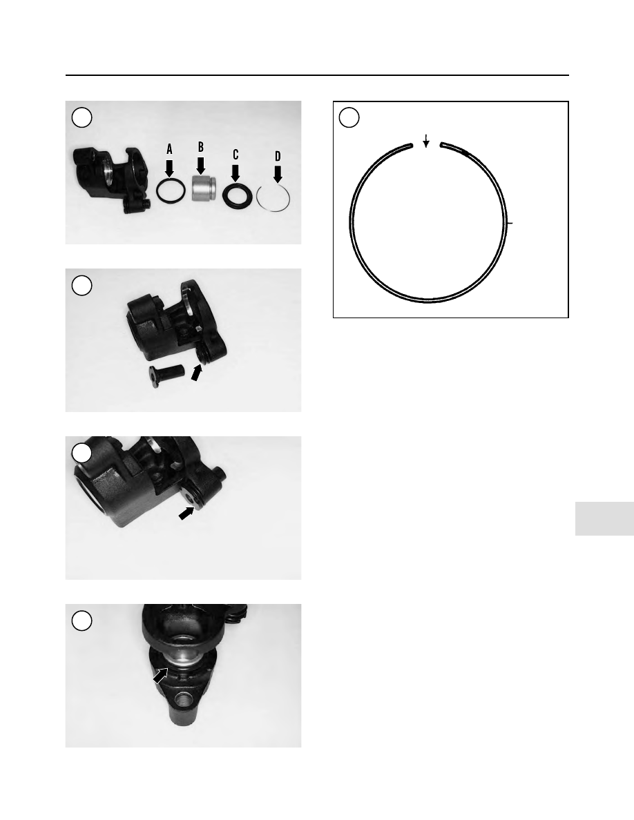
7. Install the piston dust boot on the piston before the piston
is installed in the caliper bore. Perform the following:

a. Place the piston on the workbench with its open side

facing up.

b. Align the piston dust boot with the piston so the shoul-

der on the dust boot faces up.

c. Slide the piston dust boot onto the piston until the in-

ner lip on the dust boot seats in the piston groove (Fig-
ure 40
).

8. Coat the piston and the caliper bore with DOT 5 brake
fluid.

9. Align the piston with the caliper bore so its open end faces
out (Figure 40). Then push the piston in until it bottoms.

10. Seat the piston dust boot (Figure 50) into the caliper bore.

11. Locate the retaining ring groove in the top end of the
caliper bore. Align the retaining ring so its gap (Figure 51) is
at the top of the caliper bore and install the ring into the ring
groove. Make sure the retaining ring is correctly seated in the
groove.

12. Apply a light coat of Dow Corning MOLY 44 grease to
the caliper mounting lug bores.

13. If the bleed valve assembly was removed, install it
and tighten it to 80-100 in.-lb. (9-11 N•m).

14. Install the caliper and brake pads as described in this
chapter.

15. Bleed the brakes as described under

Bleeding the Sys-

tem

in this chapter.

BRAKES

491

13

47

48

49

50

51

Align gap with top of caliper bore

Retaining
ring

BRAKE REACTION LINK

Removal/Installation (FXSTS Models)

Refer to Figure 31.

1. Remove the cotter pin, locknut (Figure 52) and shaft nut
(Figure 53) from the mounting bolt.
2. Remove the mounting bolt securing the reaction link to the
caliper mounting bracket and front fender. Do not lose the
washer (Figure 54) between the reaction link and the fender.
3. Remove the cotter pin, locknut and washer (Figure 55)
securing the reaction link to the threaded post on the rigid
fork. Discard the locknut.
4. Remove the reaction link (Figure 56) from the rigid fork
post.
5. Install the reaction link (A, Figure 57) onto the threaded post
(B) on the rigid fork. Push the reaction link on until it bottoms.
6. Install the washer and

new

locknut onto the threaded

post, Tighten the locknut (Figure 55) securely and install a

new

cotter pin. Bend the ends over completely.

7. Correctly position the reaction link with the caliper
mounting bracket and front fender.
8. Install a washer (A, Figure 58) between the reaction link
and the front fender and hold it in place and partially install
the mounting bolt (B).
9. Install the rubber spacer and washer (A, Figure 59) onto the
shaft nut, then push the mounting bolt (B) all the way through
all components. Tighten the shaft nut securely (Figure 53).
10. Install the washer (Figure 60),

new

locknut and shaft

nut (Figure 52). Tighten the locknut securely then install a

new

cotter pin. Bend the ends over completely.

11. Repeat for the other side if necessary.

Removal/Installation
(FLSTS Models)

Refer to Figure 35.

1. Remove the front brake caliper as described in this chapter.
2. Remove the front wheel as described in Chapter Nine.

492

CHAPTER THIRTEEN

52

53

54

55

56

3. Remove the front fender as described in Chapter Fourteen.
4. Remove the bolt, acorn locknut and washer securing the
brake reaction link to the caliper mounting bracket. Discard
the acorn locknut.
5. Remove the caliper mounting bracket, Teflon-coated
washer, rubber washer and left side pivot sleeve from the
fork rocker.
6. Remove the bolt, acorn locknut and washer securing the
brake reaction link to the fork leg bracket. Discard the acorn
locknut. Remove the brake reaction link.
7. If necessary, remove the bolts securing the fork leg
bracket to the rigid fork and remove the bracket.
8. Installation is the reverse of the removal steps. Note the
following:

a. Install

new

acorn locknuts.

b. Tighten locknuts to 35-40 ft.-lb. (48-54 N•m).

Inspection (All Models)

1. Check the reaction link for bending or other damage
(Figure 61).
2. Inspect the spherical bearing (Figure 62) at each end. If
damaged, replace the reaction link.
3. On FXSTS models, inspect the mounting hardware (Fig-
ure 63
) for damage.

BRAKES

493

13

57

58

59

60

61

62

FRONT BRAKE CALIPER

(ALL MODELS EXCEPT FXSTS AND FLSTS)

Removal/Installation

CAUTION

Do not spill brake fluid on the front fork or
front wheel. Wash brake fluid off any
painted, plated, or plastic surfaces immedi-
ately as it will destroy most surfaces it con-
tacts. Use soapy water and rinse completely.

1. If the caliper assembly is going to be disassembled for
service, perform the following:

NOTE

By performing Steps 1b and 1c, compressed
air may not be necessary for piston removal
during caliper disassembly.

a. Remove the brake pads as described in this chapter.

CAUTION

Do not allow the pistons to travel out far
enough to come in contact with the brake
disc. If this happens, the pistons may scratch
or gouge the disc during caliper removal.

b. Slowly apply the brake lever to push the pistons part

way out of the caliper assembly for ease of removal
during caliper service.

c. Loosen the two caliper body mounting bolts (A,

Figure 64).

d. Loosen the brake hose banjo bolt (B, Figure 64).

2. Remove the banjo bolt and sealing washers (B, Figure
64
) attaching the brake hose to the caliper assembly. Do not
lose the sealing washer on each side of the hose fittings.
3. Place the loose end of the brake hose in a reclosable
plastic bag to prevent the entry of debris and to prevent re-
sidual brake fluid from leaking out.
4. Remove the caliper mounting bolts (Figure 65) and re-
move the caliper from the front fork.
5. If necessary, disassemble and service the caliper as-
sembly as described in this chapter. If the front caliper is
not going to be serviced, place it in a reclosable plastic bag to
keep it clean.
6. Install by reversing these removal steps. Note the fol-
lowing:

a. Install the caliper assembly onto the disc, being

careful not to damage the leading edge of the brake
pads.

b. Install the bolts (Figure 65) securing the brake cali-

per assembly to the front fork and tighten them to
28-38 ft.-lb. (38-52 N•m).

c. Apply clean DOT 5 brake fluid to the rubber portions

of the new sealing washers prior to installation.

d. Install a

new

sealing washer on each side of the

brake hose fitting and install the banjo bolt (B, Fig-
ure 64
). Tighten the banjo bolt to 17-22 ft.-lb.
(23-30 N•m).

e. Bleed the brakes as described under

Bleeding the

System

in this chapter.

WARNING

Do not ride the motorcycle until the front
brake operates correctly with full hydraulic
advantage. If necessary, bleed the brakes as
described in this chapter.

494

CHAPTER THIRTEEN

63

64

65

Disassembly

1. Remove the caliper and brake pads (Figure 66) as de-
scribed in this chapter.
2. Remove the two caliper body bolts (Figure 67) loos-
ened during the removal procedure.
3. Separate the caliper body halves. Remove the O-ring
seals (Figure 68).

New

O-ring seals must be installed ev-

ery time the caliper is disassembled.

NOTE

If the pistons were partially forced out of the
caliper body during removal, Steps 4-6 may
not be necessary. If the pistons or caliper
bores are corroded or very dirty, a small
amount of compressed air may be necessary
to completely remove the pistons from the
body bores.

4. Place a piece of soft wood or a folded shop cloth over
the end of the pistons and the caliper body. Turn the as-
sembly over and place it on the workbench with the pis-
tons facing down.

WARNING

Compressed air will force the pistons out of
the caliper bodies under considerable force.

BRAKES

495

13

66

FRONT BRAKE CALIPER

(ALL MODELS EXCEPT FXSTS AND FLSTS)

1. Inboard caliper body
2. O-rings
3. Piston seal
4. Dust seal
5. Piston
6. Inboard brake pad
7. Anti-rattle spring
8. Outboard brake pad

9. Outboard caliper body

10. Cap
11. Mounting bolt
12. Bleed valve
13. Pad pin bolt
14. Trim plate
15. Caliper body bolt

67

68

Do no block the piston by hand as injury will
occur.

5. Apply the air pressure in short spurts to the hydraulic
fluid passageway to force out the pistons. Repeat this for
the other caliper body half. Use a service station air hose if
compressed air is not available.

CAUTION

In Step 6, do not use a sharp tool to remove
the dust and piston seals from the caliper
cylinders. Do not damage the cylinder sur-
face.

6. Use a piece of wood or a plastic scraper to carefully
push the dust seal and the piston seal (Figure 69) in to-
ward the caliper cylinder and out of their grooves. Re-
move the dust and piston seals.
7. If necessary, unscrew and remove the bleed valve (A,
Figure 70).
8. Inspect the caliper assembly as described in this sec-
tion.

Inspection

1. Clean both caliper body halves and pistons in clean
DOT 5 brake fluid or isopropyl alcohol, and dry them with
compressed air.
2. Make sure the fluid passageways (Figure 71) in the
piston bores are clear. Apply compressed air to the open-
ings to make sure they are clear. Clean them out, if neces-
sary, with clean brake fluid.
3. Make sure the fluid passageways (A, Figure 72) in
both caliper body halves are clear. Apply compressed air
to the openings to make sure they are clear. Clean them
out, if necessary, with clean brake fluid.
4. Inspect the piston and dust seal grooves (Figure 73) in
both caliper bodies for damage. If they are damaged or
corroded, replace the caliper assembly.
5. Inspect the banjo bolt threaded hole (B, Figure 70) in
the outboard caliper body. If it is worn or damaged, clean
it out with a metric thread tap or replace the caliper assem-
bly.
6. Inspect the bleed valve threaded hole in the caliper
body. If it is worn or damaged, clean it out with a metric
thread tap or replace the caliper assembly.
7. Inspect the bleed valve. Apply compressed air to the
opening and make sure it is clear. Clean it out, if neces-
sary, with clean brake fluid. Install the bleed valve and
tighten it to 80-100 in.-lb. (9-11 N•m).
8. Inspect both caliper bodies for damage. Check the in-
board caliper mounting bolt hole threads (B, Figure 72)

496

CHAPTER THIRTEEN

69

70

71

72

for wear or damage. Clean the threads with an appropri-
ately sized metric tap or replace the caliper assembly.

9. Inspect the cylinder walls and pistons for scratches,
scoring or other damage.

10. Check the anti-rattle spring (Figure 74) for wear or
damage.

Assembly

WARNING

Never reuse old dust seals or piston seals.
Very minor damage or age deterioration
can make the seals ineffective.

1. Soak the new dust and piston seals in clean DOT 5
brake fluid.

2. Coat the piston bores and pistons with clean DOT 5
brake fluid.

3. Carefully install the new piston seals into the lower
grooves. Make sure the seals are properly seated in their
respective grooves.

4. Carefully install the new dust seals into the upper
grooves. Make sure all seals are properly seated in their
respective grooves (Figure 75).

5. Repeat Step 3 and Step 4 for the other caliper body
half.

6. Position the pistons with the open end facing out and
install the pistons into the caliper cylinders (A, Figure
76
). Push the pistons in until they bottom (B, Figure 76).

7. Repeat Step 6 for the other caliper body half. Make
sure all pistons are installed correctly.

8. Coat the

new

O-ring seals in DOT 5 brake fluid and in-

stall the O-rings (Figure 68) into the inboard caliper half.

9. Install the anti-rattle spring (Figure 77) onto the boss
on the outboard caliper half.

10. Make sure the O-rings are still in place and assemble
the caliper body halves.

BRAKES

497

13

73

74

75

76

77

WIRING DIAGRAMS

613

17

Neutral

indicator

switch

Oil

pressure

switch

Left
rear turn
signal

19

32

93

94

18

Gnd 3

Gnd

1 & 2

Battery

Fender tip
light for US
FLSTC only

Spark

plugs

Crank

position

sensor

Cam

position

sensor

79

14

121

120

131

Diagram Key

Connectors

Ground

Frame ground

No connection

Connection

Rear

brake

switch

46

61

128

Stator

Ignition

coil

Starter

solenoid/

Motor

10

11

(Gray)

(Black)

Ignition module

Circuit
breaker
30A

Manifold

air press.

sensor

80

134

Bank angle

sensor

Tail
light

Right
rear turn
signal

Running

light (HDI)

Running

light (DOM)

Note:
The voilet and brown wires are transposed
on connector 94 on the FXST/S/B inverted
tail light mount.

7

83

2

3

4

6

5

12

11

10

9

8

7

1

2

3

4

6

5

12

11

10

9

8

7

1

Voltage

regulator

B

A

C

Starter

relay

a

86 85

87

30

87

614

WIRING DIAGRAMS

Fuel gauge

(FXSTD only)

65

154

39

21

Neutral

indicator

High beam

indicator

Position

light

(HDI only)

Left turn

signal

indicator

Right turn

signal

indicator

Oil press.

indicator

Headlight

Right

passing

light

Left

passing

light

Right

front turn

signal

Left

front turn

signal

Tach. Connector,
pin 6 speedomtr.

(optional)

Left

turn signal

switch

Emergency

stop

switch

Starter

switch

74

117

Main

harness

73

108

31

38

Lights

15A

Instr

15A

Acc

15A

Security

15A

Ign.

15A

Right

turn signal

switch

Function/

tripmeter

reset switch

Passing

lights

switch

Horn

142

122

24

22

Siren

(optional)

Horn

switch

Front

brake

switch

Headlight

dimmer switch

High

Low

Speed

sensor

30

Ignition

2

Vss/serial

data

link

3

Security

indicator

4

Right

turn

feed

6

Left

turn

feed

5

Gr

ound

12

Alarm

signal

11

Ignition

enab

le

sig

10

Star

t

rela

y

contr

ol

9

Left

turn

s

w

input

8

Right

turn

s

w

input

7

Batter

y

1

Turn signal/

Security module

Fuel level

sender

141

Speedometer

To data

link

91

Off

Acc

Ign

Ignition

switch

33

2001-2003 FLSTS AND FXSTD DOMESTIC AND HDI CARBURETED MODELS

WIRING DIAGRAMS

615

17

Neutral

indicator

switch

Oil

pressure

switch

Left
rear turn
signal

18

45

32

93

19

Gnd 2

Gnd 1

Battery

Fender tip
light for US
FLSTC only

Spark

plugs

Crank

position

sensor

79

121

120

131

Diagram Key

Connectors

Ground

Frame ground

No connection

Connection

Rear

brake

switch

46

62

128

Stator

Ignition

coil

Starter

solenoid/

Motor

10

11

(Gray)

(Black)

Ignition module

Circuit
breaker
30A

Manifold

air press.

sensor

80

Tail
light

Right
rear turn
signal

License
plate lights
(FXSTD only)

7

83

2

3

4

6

5

12

11

10

9

8

7

1

2

3

4

6

5

12

11

10

9

8

7

1

Voltage

regulator

B

A

C

Starter

relay

a

86 85

87

30

87

616

WIRING DIAGRAMS

Fuel gauge

(FXSTD only)

65

154

39

21

Neutral

indicator

High beam

indicator

Position

light

(HDI only)

Left turn

signal

indicator

Right turn

signal

indicator

Oil press.

indicator

Headlight

Right

passing

light

Left

passing

light

Right

front turn

signal

Left

front turn

signal

Tach. Connector,
pin 6 speedomtr.

(optional)

Left

turn signal

switch

Emergency

stop

switch

Starter

switch

74

117

Main

harness

73

108

31

38

Lights

15A

Instr

15A

Acc

15A

Security

15A

Ign.

15A

Right

turn signal

switch

Function/

tripmeter

reset switch

Passing

lights

switch

Horn

142

122

24

22

Siren

(optional)

Horn

switch

Front

brake

switch

Headlight

dimmer switch

High

Low

Speed

sensor

30

Ignition

2

Vss/serial

data

link

3

Security

indicator

4

Right

turn

feed

6

Left

turn

feed

5

Gr

ound

12

Alarm

signal

11

Ignition

enab

le

sig

10

Star

t

rela

y

contr

ol

9

Left

turn

s

w

input

8

Right

turn

s

w

input

7

Batter

y

1

Turn signal/

Security module

Fuel level

sender

141

Speedometer

To data

link

91

Off

Acc

Ign

Ignition

switch

33

2001-2003 ALL DOMESTIC AND HDI CARBURETED SOFTAIL MODELS EXCEPT

FLSTS AND FXSTD

WIRING DIAGRAMS

617

17

Neutral

indicator

switch

Oil

pressure

switch

Gnd 2

Gnd 1

Battery

Spark

plugs

Crank

position

sensor

79

121

120

131

Rear

brake

switch

46

62

128

Stator

Ignition

coil

Starter

solenoid/

Motor

10

11

(Gray)

(Black)

Ignition module

Circuit
breaker
30A

Manifold

air press.

sensor

80

7

83

2

3

4

6

5

12

11

10

9

8

7

1

2

3

4

6

5

12

11

10

9

8

7

1

Voltage

regulator

B

A

C

Left
rear turn
signal

19

32

93

94

18

Fender tip
light for US
FLSTC only

Diagram Key

Connectors

Ground

Frame ground

No connection

Connection

Tail
light

Right
rear turn
signal

Running

light (HDI)

Running

light (DOM)

Note:
The voilet and brown wires are transposed
on connector 94 on the FXST/S/B inverted
tail light mount.

Starter

relay

a

86 85

87

30

87

618

WIRING DIAGRAMS

Fuel

gauge

65

154

39

21

Neutral

indicator

High beam

indicator

Front

fender

tip light

Left turn

signal

indicator

Right turn

signal

indicator

Oil press.

indicator

Headlight

Right

passing

light

Left

passing

light

Right

front turn

signal

Left

front turn

signal

Tachometer

connector

(optional)

Left

turn signal

switch

Emergency

stop

switch

Starter

switch

74

117

Main

harness

73

108

31

32

143

38

Lights

15A

Instr

15A

Acc

15A

ECM

15A

Fuel

pump

15A

Security

15A

Ign.

15A

Right

turn signal

switch

Function/

tripmeter

reset switch

Passing

lights

switch

Horn

142

122

24

22

Siren

(optional)

Horn

switch

Front

brake

switch

Headlight

dimmer switch

High

Low

Speed

sensor

30

Ignition

2

Vss/serial

data

link

3

Security

indicator

4

Right

turn

feed

6

Left

turn

feed

5

Gr

ound

12

Alarm

signal

11

Ignition

enab

le

sig

10

Star

t

rela

y

contr

ol

9

Left

turn

s

w

input

8

Right

turn

s

w

input

7

Batter

y

1

Turn signal/

Security module

Fuel pump/

Sender

86

Speedometer

To data

link

91

Off

Acc

Ign

Ignition

switch

33

2001-2003 FLSTS AND FXSTD DOMESTIC AND HDI EFI MODELS

WIRING DIAGRAMS

619

17

Neutral

indicator

switch

Oil

pressure

switch

Left
rear turn
signal

18

45

32

93

19

85

84

Gnd 3

Gnd

1 & 2

Battery

Fender tip
light for US
FLSTC only

Spark

plugs

Crank

position

sensor

79

121

120

131

Diagram Key

Connectors

Ground

Frame ground

No connection

Connection

Rear

brake

switch

46

62

128

Stator

Ignition

coil

Starter

solenoid/

Motor

Starter

relay

78

Chec

k

engine

light

2

T

ac

h

output

3

System

rela

y

4

Engine

temp.

6

Serial

data

link

5

Idle

air

contr

ol

36

Idle

air

contr

ol

18

Idle

air

contr

ol

35

Idle

air

contr

ol

17

Digital

po

wer

NC 34

Frequenc

y

input

NC 16

Digital

gr

ound

NC 15

5V

sensor

po

wer

14

Switc

h

po

wer

13

Speed

sensor

input

33

Constant

po

wer

31

CKP

sensor

30

CKP

sensor

12

Coil,

fr

ont

29

Coil,

rear

11

P

o

wer

gr

ound

10

Bank

angle

NC

9

O2

sensor

input

NC

8

Intake

air

temp.

7

P

o

wer

gr

ound

28

Ion

sense

27

5V

sensor

gr

ound

26

MAP

sensor

input

25

TPS

input

24

Analog/O2

input

NC 23

HDI

solenoid

NC 22

Injector

,

fr

ont

21

Injector

,

rear

19

Flash

pin

NC 20

Switc

h

input

NC 32

Flash

pin

1

ECM

System

relay

Circuit

breaker

Rear fuel
injector

Front fuel
injector

Manifold

air press.

sensor

Engine

temp.

sensor

80

90

89

Intake air

temp.

sensor

88

Throttle

position

sensor

Tail
light

Right
rear turn
signal

License
plate lights
(FXSTD only)

7

87

Idle air

control

Voltage

regulator

83

a

86 85

87

30

87

a

86 85

87

30

87

B Ion sen

Coil rear

Coil frt

A pwr

C

D

620

WIRING DIAGRAMS

Fuel

gauge

65

154

39

21

Neutral

indicator

High beam

indicator

Front

fender

tip light

Left turn

signal

indicator

Right turn

signal

indicator

Oil press.

indicator

Headlight

Right

passing

light

Left

passing

light

Right

front turn

signal

Left

front turn

signal

Tachometer

connector

(optional)

Left

turn signal

switch

Emergency

stop

switch

Starter

switch

74

117

Main

harness

73

108

31

32

143

38

Lights

15A

Instr

15A

Acc

15A

ECM

15A

Fuel

pump

15A

Security

15A

Ign.

15A

Right

turn signal

switch

Function/

tripmeter

reset switch

Passing

lights

switch

Horn

142

122

24

22

Siren

(optional)

Horn

switch

Front

brake

switch

Headlight

dimmer switch

High

Low

Speed

sensor

30

Ignition

2

Vss/serial

data

link

3

Security

indicator

4

Right

turn

feed

6

Left

turn

feed

5

Gr

ound

12

Alarm

signal

11

Ignition

enab

le

sig

10

Star

t

rela

y

contr

ol

9

Left

turn

s

w

input

8

Right

turn

s

w

input

7

Batter

y

1

Turn signal/

Security module

Fuel pump/

Sender

86

Speedometer

To data

link

91

Off

Acc

Ign

Ignition

switch

33

2001-2003 ALL DOMESTIC AND HDI EFI SOFTAIL MODELS EXCEPT FLSTS AND FXSTD

WIRING DIAGRAMS

621

17

Left
rear turn
signal

19

32

93

94

18

Fender tip
light for US
FLSTC only

Diagram Key

Connectors

Ground

Frame ground

No connection

Connection

Tail
light

Right
rear turn
signal

Running

light (HDI)

Running

light (DOM)

Note:
The voilet and brown wires are transposed
on connector 94 on the FXST/S/B inverted
tail light mount.

7

Neutral

indicator

switch

Oil

pressure

switch

85

84

Gnd 3

Gnd

1 & 2

Crank

position

sensor

79

121

120

131

Rear

brake

switch

46

Stator

78

Chec

k

engine

light

2

T

ac

h

output

3

System

rela

y

4

Engine

temp.

6

Serial

data

link

5

Idle

air

contr

ol

36

Idle

air

contr

ol

18

Idle

air

contr

ol

35

Idle

air

contr

ol

17

Digital

po

wer

NC 34

Frequenc

y

input

NC 16

Digital

gr

ound

NC 15

5V

sensor

po

wer

14

Switc

h

po

wer

13

Speed

sensor

input

33

Constant

po

wer

31

CKP

sensor

30

CKP

sensor

12

Coil,

fr

ont

29

Coil,

rear

11

P

o

wer

gr

ound

10

Bank

angle

NC

9

O2

sensor

input

NC

8

Intake

air

temp.

7

P

o

wer

gr

ound

28

Ion

sense

27

5V

sensor

gr

ound

26

MAP

sensor

input

25

TPS

input

24

Analog/O2

input

NC 23

HDI

solenoid

NC 22

Injector

,

fr

ont

21

Injector

,

rear

19

Flash

pin

NC 20

Switc

h

input

NC 32

Flash

pin

1

ECM

Rear fuel
injector

Front fuel
injector

Manifold

air press.

sensor

Engine

temp.

sensor

80

90

89

Intake air

temp.

sensor

88

Throttle

position

sensor

87

Idle air

control

Battery

Spark

plugs

62

128

Ignition

coil

Starter

solenoid/

Motor

Starter

relay

System

relay

Circuit

breaker

87

Idle air

control

83

a

86 85

87

30

87

a

86 85

87

30

87

B Ion sen

Coil rear

Coil frt

A pwr

C

D

Voltage

regulator


Content      ..     27      28      29      30     ..