Harley Davidson Softail 2000-2005. Service manual - page 27
 

  Главная      Harley Davidson     Harley Davidson Softail 2000-2005. Service manual


Search            copyright infringement  


Content      ..     25      26      27      28     ..


Harley Davidson Softail 2000-2005. Service manual - page 27


FRONT SUSPENSION AND STEERING (SPRINGER FORK)

459

11

97

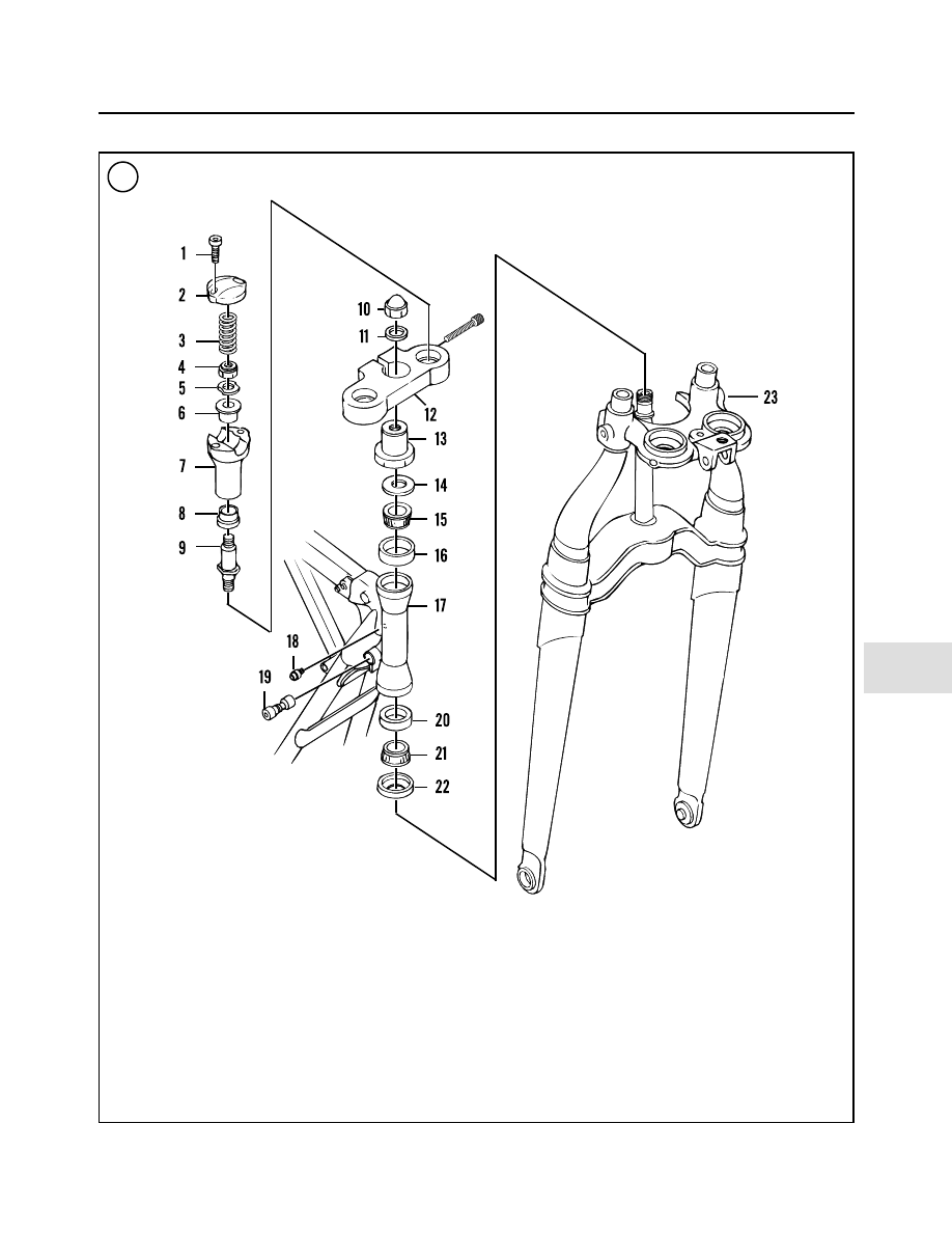
RIGID FORK AND STEERING STEM (FLSTS)

1. Bolt
2. Clamp
3. Ground spring
4. Locknut
5. Washer
6. Rubber bushing
7. Riser
8. Rubber bushing
9. Threaded stud

10. Acorn nut
11. Washer
12. Upper bracket

13. Bearing retainer
14. Dust shield
15. Upper bearing
16. Upper bearing race
17. Steering head/frame
18. Grease fitting
19. Steering lock
20. Lower bearing race
21. Lower bearing
22. Dust shield
23. Rigid fork

removed in Step 15. Secure the rigid fork
prior to removing the bearing retainer.

15. Loosen and remove the bearing retainer (Figure 102)
and the dust shield (Figure 103).
16. Carefully slide the rigid fork assembly down and out
of the steering head (A, Figure 104).
17. If necessary, remove the upper bearing (B, Figure
104
) from the steering head.

Inspection

Harley-Davidson does not provide any inspection spec-

ifications for the rigid fork assembly. Visually inspect the
components for wear, damage or deterioration. If the front
end was involved in an accident, have the motorcycle in-
spected by a Harley-Davidson dealership or competent
motorcycle frame specialist.
1. Clean all parts in solvent and dry with compressed air.
2. Inspect the rigid fork assembly for cracks, bending or
other damage. If visual inspection indicated that the rigid
fork is bent, have it inspected by a Harley-Davidson deal-
ership or competent motorcycle frame specialist.
3. Check the rigid fork leg stud threads for being stripped
or cross-threaded. Check the threaded portion on both
ends of the stud for bending or other damage. Repair or re-
place the studs if necessary.
4. Check the rigid fork leg stud threaded holes in the rigid
fork for being stripped or cross-threaded. Repair the
threads if necessary.
5. Use compressed air and thoroughly clean out the
threaded holes of all debris. Any buildup in the hole may
hamper the threaded stud from being tightened to the cor-
rect torque.
6. Inspect the upper bracket for cranks or damage.
7. Inspect the bearing retainer for damage and thread
damage. Repair the threads if necessary. If the hex portion
of the bearing retainer is rounded off, replace it.
8. Inspect the steering stem portion and steering stem
bearings as described under

Steering Stem

in this chapter.

Installation

1. Make sure the upper and lower bearing outer races are
properly seated in the steering stem. Apply a light coat of
bearing grease to each bearing race.
2. Pack the upper and lower bearings with grease before
installation.
3. With the help of an assistant, carefully slide the rigid
fork assembly up and into the steering head. Hold the fork
assembly in place, then install the upper bearing onto the

460

CHAPTER ELEVEN

98

99

100

101

steering stem and push it down into the upper bearing race
(B, Figure 104).

4. Install the dust shield (Figure 103) over the fork stem.
Position the bearing retainer with the hex head facing
down and install it onto the steering stem (Figure 102).

5. Tighten the bearing retainer as follows:

a. Tighten the bearing retainer to 40 ft.-lb. (54 N•m).

b. Loosen the bearing retainer and retighten to 72

in.-lb. (8 N•m).

6. Turn the rigid fork assembly from side-to-side; the
fork should pivot smoothly with no sign of roughness or

tightness. If the fork does not pivot smoothly, remove the
bearing retainer and recheck the bearings and fork stem.
7. Install the upper bracket onto the steering stem and
rigid fork legs. Make sure it is seated correctly.
8. Install both rigid fork leg studs as follows:

a. Thread both studs into the fork legs and tighten

hand-tight.

b. Tighten both studs to 60-65 ft.-lb. (81-88 N•m).

9. Install the upper bracket clamp bolt (Figure 98) and
tighten to 25-30 ft.-lb. (34-41 N•m).
10. Install a

new

rubber washer and the acorn nut (C, Fig-

ure 99). Tighten the acorn nut to 30-35 ft.-lb. (41-48
N•m).
11. Adjust the steering as described under

Steering Ad-

justment

in this chapter.

12. Once again, turn the rigid fork assembly from
side-to-side; the fork should pivot smoothly with no sign
of roughness or tightness. If the fork does not pivot
smoothly, readjust the steering as described in this chap-
ter.
13. Move the brake line assembly into position on the
base of the rigid fork below the steering stem. Install the
bolt and bracket (Figure 101) and tighten securely.
14. Move the front brake line onto the side of the rigid
fork and install the bolt and bracket (Figure 100). Tighten
the bolt securely.
15. If removed, install the spring fork as described in this
chapter.
16. Install the risers (B, Figure 99) and the handlebar as
described in Chapter Ten.
17. Install the front fender as described in Chapter Four-
teen.
18. Install the front brake caliper as described in Chapter
Thirteen.
19. Install the front wheel as described in Chapter Nine.
20. On FLSTS models, install the passing lamp assembly
as described in Chapter Eight.
21. Install the headlight assembly (A, Figure 99) as de-
scribed in Chapter Eight.
22. Install the shock absorber as described in this chapter.
23. Remove the handlebar as described in this chapter.
24. Lower the motorcycle to the ground and place it on
the jiffy stand.
25. Apply the front brake and compress the front suspen-
sion several times and make sure there is no binding or ab-
normal noise.
26. Test ride the motorcycle slowly at first to make sure
the front suspension is operating correctly.

WARNING

Do not ride the motorcycle until the front
brake is operating correctly with full hy-

FRONT SUSPENSION AND STEERING (SPRINGER FORK)

461

11

102

103

104

draulic advantage and that the front suspen-
sion is operating correctly.

STEERING STEM

Steering Stem and Bearing Inspection

The upper and lower bearing outer races are pressed

into the frame. Do not remove the bearing races unless
they will be replaced.
1. Remove the entire fork assembly as described in this
chapter.
2. If still in place, remove the upper bearing from the
steering head.
3. Wipe the bearing races with a solvent soaked rag and
then dry with compressed air or a lint-free cloth. Check
the races in the steering head for pitting, scratches, galling
or excessive wear. Refer to Figure 105 and Figure 106. If
any of these conditions exist, replace the races as de-
scribed in this chapter. If the races are good, wipe each
race with grease.
4. Clean the bearings in solvent to remove all of the old
grease. Blow the bearing dry with compressed air, making
sure not to allow the air jet to spin the bearing. Do not re-
move the lower bearing from the fork stem unless it is to
be replaced. Clean the bearing while installed in the steer-
ing stem.
5. After the bearings are dry, hold the inner race with one
hand and turn the bearing with the other hand. Turn the
bearing slowly, the bearing must turn smoothly with no
roughness. Visually check the bearing (Figure 107) for
pitting, scratches or visible damage. If the bearings are
worn, check the dust covers for wear or damage or for im-
proper bearing lubrication. Replace the bearing if neces-
sary. If a bearing is going to be reused, pack it with grease
and wrap it with wax paper or another type of lint-free ma-
terial until it is reinstalled. Do not store the bearings for
any length of time without lubricating them to prevent
rust.
6. Check the steering stem for cracks or damage. Check
the threads (Figure 108) at the top of the stem for damage.
Check the bearing retainer (Figure 109) for damage.
Thread it into the steering stem; make sure the nut threads
easily with no roughness.
7. Replace all worn or damaged parts. Replace bearing
races as described in this chapter.
8. Replace the lower steering stem bearing and the dust
shield as described in this chapter.
9. Check for broken welds on the frame around the steer-
ing head. If any are found, have them repaired by a com-
petent frame shop or welding service familiar with
motorcycle frame repair.

462

CHAPTER ELEVEN

105

106

107

108

Steering Head Bearing Race Replacement

The upper and lower bearing outer races are pressed

into the frame. Do not remove the bearing races unless re-
placement is necessary. If removed, replace both the outer
race along with the bearing at the same time. Never rein-
stall an outer race that has been removed as it is no longer
true and will damage the bearing.
1. Remove the entire fork assembly as described in this
chapter.
2. If still in place, remove the upper bearing from the
steering head.
3. To remove a race, insert an aluminum or brass rod into
the steering head and carefully tap the race out from the
inside (Figure 110). Tap all around the race so that neither
the race nor the steering head is bent.
4. Clean the steering head with solvent and dry thor-
oughly.
5A. Install the bearing races with steering head bearing
race installer tool (JIMS part No. 1725) (Figure 111) fol-
lowing the manufacturer’s instructions.
5B. If the special tools are not available, install the bear-
ing races as follows:

a. Clean the race thoroughly before installing it.
b. Align the upper race with the frame steering head

(Figure 112) and tap it slowly and squarely in place.
Do not contact the bearing race surfaces. See Fig-
ure 113
. Drive the race into the steering head until it
bottoms out on the bore shoulder.

c. Repeat to install the lower race into the steering

head.

6. Apply bearing grease to the face of each race.

Steering Stem Lower Bearing Replacement

Do not remove the steering stem lower bearing and

lower seal unless it is going to be replaced. The lower
bearing can be difficult to remove. If the lower bearing

FRONT SUSPENSION AND STEERING (SPRINGER FORK)

463

11

109

110

111

112

cannot be removed as described in this procedure, take the
steering stem to a Harley-Davidson dealership.

Never reinstall a lower bearing that has been removed

since it is no longer true and will damage the rest of the
bearing assembly.

1. Install the steering stem bearing retainer and acorn nut
onto the top of the steering stem to protect the threads.

2. Remove the lower bearing (Figure 114) as follows:

a. Place two large wide-blade screwdrivers into the

fork stem bracket as shown in Figure 115.

b. Slowly pry the lower bearing and dust shield up and

off the steering stem raised shoulder.

c. Slide the lower bearing and dust shield off the steer-

ing stem.

3. Clean the steering stem with solvent and dry thor-
oughly.

4. Position the new lower dust shield with the flange side
facing up.

5. Slide a new the lower bearing onto the steering stem
until it stops on the raised shoulder.

6. Align the lower bearing with the machined shoulder on
the steering stem. Press or drive the lower bearing onto the
steering stem until it bottoms (Figure 114).

7. If necessary, have the fork steering stem (Figure 116)
replaced by a Harley-Davidson dealership.

STEERING PLAY ADJUSTMENT

Steering Tool Fabrication

By using this special tool, the steering head bearings

can be adjusted with the handlebar, risers, rigid fork leg
studs and upper bracket in place.

A steering adjustment tool must be fabricated to adjust

the steering. Purchase the bearing retainer (part No.
48306-88) and three roll pins (part No. 614) from a
Harley-Davidson dealership. See Figure 117.

Use a hacksaw and cut the pins so approximately 0.5 in.

(12.7 mm) of the pin protrudes from the bottom surface of
the retaining nut (Figure 118).

Coat the ends of the pins with Loctite Retaining Com-

pound 620, or an equivalent, and insert them into the
pre-drilled holes on the retaining nut. Allow the com-
pound to set prior to using the tool.

CAUTION

Do not use this tool to seat the upper bear-
ing retainer nut. High torque will bend the
pins in the tool.

464

CHAPTER ELEVEN

113

Wood
block

Head
tube

Race

114

115

Adjustment (FXSTS Models)

The motorcycle must be equipped with only the factory

installed components. If any aftermarket components
have been installed, they must be removed at this time as
they could affect this adjustment.

1. Use a centrally located floor jack under the frame. Sup-
port the motorcycle with both the front and rear wheels off
the ground the same distance. If necessary, place a

wooden block(s) under the rear wheel until the motorcy-
cle is level.
2. Disconnect the clutch cable from the handlebar. Refer
to Chapter Five.
3. Disconnect the throttle cables from the handlebar. Re-
fer to Chapter Seven.
4. Remove the acorn nut and rubber washer (C, Figure
99
).
5. Loosen, but do not remove, the upper bracket pinch
bolt (Figure 98).
6. Apply a strip of masking tape across the front end of
the front fender. Draw a vertical line across the tape at the
center of the fender.
7. Turn the handlebar so that the front wheel faces
straight ahead.
8. Install pointer so the base is stationary on the floor and
the pointer indicates the center of the fender tape mark
when the wheel is facing straight ahead.
9. Lightly push the fender toward the right side until the
front end starts to turn by itself. Mark this point on the
tape.
10. Repeat Step 9 for the left side.
11. Measure the distance between the two marks on the
tape. The correct distance is 1-2 in. (25-51 mm). If the dis-
tance is incorrect, perform Step 12.
12. If necessary, use the special tool and loosen or tighten
the steering stem bearing retainer nut or bolt until the
measurement is within the limits:

a. If the distance is more than 2 in. (51 mm) loosen the

bearing retainer nut.

b. If the distance is less than 1 in. (25 mm) tighten the

bearing retainer nut.

13. If used, remove the special tool from the bearing re-
tainer.
14. Tighten the upper bracket pinch bolt (Figure 98) to
25-30 ft.-lb. (34-41 N•m).
15. Tighten the acorn nut and rubber washer (Figure 99)
to 30-35 ft.-lb. (41-48 N•m).
16. Lower the motorcycle to the ground.

Adjustment (FLSTS Models)

The motorcycle must be equipped with only the factory

installed components. If any aftermarket components
have been installed, they must be removed at this time as
they could affect this adjustment.

NOTE

The fork has more weight on the right side
than on the left side. The balance point is
just off the full left lock position.

FRONT SUSPENSION AND STEERING (SPRINGER FORK)

465

11

118

116

117

Pin

Hex bearing
retainer

0.5 in.
(12.7 mm)

1. Use a centrally located floor jack under the frame. Sup-
port the motorcycle with both the front and rear wheels off
the ground the same distance. If necessary, place a wooden
block(s) under the rear wheel until the motorcycle is level.
2. Disconnect the clutch cable from the handlebar. Refer
to Chapter Five.
3. Disconnect the throttle cables from the handlebar. Re-
fer to Chapter Seven.
4. Remove the acorn nut and rubber washer (Figure 119).
5. Loosen, but do not remove the upper bracket pinch bolt
(Figure 120).
6. Turn the fork to full left lock.
7. Hang a plumb bob from the hole in the rear of the
fender.
8. Place a ruler on the floor directly under the plumb bob
with the plumb bob pointing directly at zero.

9. Align the pins on the special tool with the holes in the
bearing retainer (Figure 121). Push the tool in until it
seats correctly (Figure 122).
10. Move the front wheel to the balance point and tap it
until it begins to fall away

to the right

. Measure the dis-

tance from zero to the fall-away. Steering adjustment is
correct when the zero to fall-away distance is 4-6 in.
(101.6-152.4 mm). If necessary, use the special tool and
adjust the bearing retainer until the adjustment is correct.
11. If used, remove the special tool from the bearing re-
tainer.
12. Tighten the upper bracket pinch bolt (Figure 120) to
25-30 ft.-lb. (34-41 N•m).
13. Tighten the acorn nut and rubber washer (Figure 119)
to 30-35 ft.-lb. (41-48 N•m).
14. Lower the motorcycle to the ground.

466

CHAPTER ELEVEN

120

121

122

119

Table 1 FRONT SUSPENSION TORQUE SPECIFICATIONS (SPRINGER)

Item

ft.-lb.

in.-lb.

N•m

Bearing retainer

25-35

3-4

Bearing adjuster jam nut

95-105

129-143

Handlebar

Clamp bolts

144-180

16-20

Riser lock nuts

25-35

34-47

Riser threaded stud

60-65

81-88

Rocker pivot stud

Acorn or hex nut

45-50

61-68

Rigid fork leg studs

60-65

81-88

Rigid fork steering stem bearing retainer

Preliminary

40

54

Final

72

8

Acorn nut

30-35

41-48

Shock absorber acorn nut

45-50

61-68

Spring bridge acorn nuts

30-35

41-48

Spring rod acorn nut

20-25

27-34

Upper bracket pinch bolt

25-30

34-41

FRONT SUSPENSION AND STEERING (SPRINGER FORK)

467

11

CHAPTER TWELVE

REAR SUSPENSION

This chapter includes repair and replacement proce-

dures for the rear suspension components. Table 1 is lo-
cated at the end of this chapter.

WARNING

All fasteners used on the rear suspension
must be replaced with parts of the same
type. Do not use a replacement part of lesser
quality or substitute design. It may affect the
performance of the rear suspension or fail,
leading to loss of control of the motorcycle.
Use the torque specifications in

Table 1

dur-

ing installation to ensure proper retention of
these components.

SPRING PRELOAD ADJUSTMENT

The shock absorber spring preload can be adjusted to

compensate for the weight the motorcycle is to carry. A
special tool is required for this procedure. The spanner
wrench (HD-94455-89) is included in the motorcycle tool
kit (Figure 1).
1. Thoroughly clean the threads on the shock absorber
mount prior to loosening the locknut in Step 2. Remove all
dirt and road debris to avoid damage to the threads.
2. Working under the motorcycle, loosen the locknut
(Figure 2) on both shock absorber shafts. The locknut is
located at the front of the shock absorber.

3. Mark alignment marks on the adjuster plate and the
shock absorber case on each shock absorber.
4. Using the spanner wrench, rotate the adjuster plate in
the following directions:

a. To increase spring preload, rotate the adjuster plate

out toward the locknut.

b. To decrease spring preload, rotate the adjuster plate

in toward the locknut.

5. Adjust both shock absorbers to the same setting.
6. Tighten the locknuts securely.

SHOCK ABSORBERS

All models are equipped with dual shock absorbers lo-

cated horizontally under the transmission case.

Removal/Installation

Refer to Figure 3.
One special tool is required for shock absorber removal

and installation. Use a Snap-on adapter (part No.
SRES24), or an equivalent ratchet wrench, to access the
bolt securing the shock absorber to the swing arm.

NOTE

This procedure is shown with the rear wheel
removed to better illustrate the steps.

1. Support the motorcycle with the rear wheel

slightly

off

the ground. See

Motorcycle Stands

in Chapter Nine.

2. On models so equipped, remove the saddlebags as de-
scribed in Chapter Fourteen.

3. Using the special tool, remove the bolt and washer
(Figure 4) securing the shock absorbers to the rear swing
arm.

4. Remove the flange locknut and washer/grommet se-
curing the shock absorber stud to the frame cross member
(Figure 5).

5. Pull the shock absorber to the rear (Figure 6) and re-
move it from the motorcycle. Do not lose the bushing on
the shock absorber stud.

6. Inspect the shock absorber as described in this chapter.

7. Install the bushing onto the end of the shock absorber
stud.

8. Place the washer/grommet onto the inside surface of
the frame and insert the shock absorber stud through the
washer/grommet.

9. Install the flange locknut and tighten finger-tight.

10. Apply a few drops of ThreeBond TB1342, or an
equivalent, to the shock mounting bolt threads.
11. Move the shock absorber into position on the rear
swing arm and install the mounting bolt washer securing
the shock absorber to the swing arm.
12. Tighten the mounting bolt and the flange locknut to
the specifications in Table 1.
13. Repeat Steps 8-12 for the other shock absorber if nec-
essary.
14. Adjust both shock absorbers equally as described in
this chapter.
15. On models so equipped, install the saddlebag(s) as
described in Chapter Fourteen.
16. Lower the motorcycle and test ride it to make sure the
rear suspension is working properly.

Inspection

There are no shock replacement parts available for

these models. If any part requires replacement, other than
the mounting hardware, replace the shock assembly.
1. Remove the shock absorber as described in this chap-
ter.
2. Inspect the shock bushing (Figure 7) for wear and de-
terioration.
3. Inspect the threaded stud (A, Figure 8) and nut (B) for
thread damage and clean up if necessary.
4. Check the bushing (C, Figure 8) for wear.
5. Inspect the grommet/washer combination (Figure 9)
for hardness or deterioration.
6. Check the adjuster locknut (Figure 10) for damage and
for tightness.
7. Inspect the shock absorber body (Figure 11) for dam-
age, replace the shock absorber if necessary.
8. Inspect the mounting bolt (Figure 12) for thread dam-
age and clean up if necessary.

REAR SWING ARM

Rear Swing Arm Bearing Check

The swing arm bearings are sealed and lifetime lubri-

cated. These bearings do not require any routing service
and should last the life of the motorcycle unless they are
damaged due to an accident or abuse. Worn or damaged
bearings can produce erratic and dangerous handling.
Common symptoms are wheel hop, pulling to one side
during acceleration and pulling to the other side during
braking.
1. On models so equipped, remove the saddlebags as de-
scribed in Chapter Fourteen.
2. Remove the rear wheel as described in Chapter Nine.

REAR SUSPENSION

469

12

1

Spanner
wrench

2

3. Make sure the nut (Figure 13) securing the rear swing
arm pivot shaft is tight.

4. Have an assistant hold the motorcycle securely.

5. Grasp the back of the rear swing arm and try to move it
from side to side. Any play between the rear swing arm
and the frame may indicate worn or damaged bearings. If
there is any play, remove the swing arm and inspect the
bearings.

6. Install the rear wheel as described in Chapter Nine.

7. On models so equipped, install the saddlebags as de-
scribed in Chapter Fourteen.

470

CHAPTER TWELVE

3

REAR SUSPENSION

1. Axle adjust screw nut
2. Axle adjuster
3. Swing arm
4. Axle adjust screw
5. Hardened washer
6. Retaining ring
7. Bearing
8. Flange nut
9. Speed nut

10. Bushing
11. Spacer collar
12. Pivot shaft
13. Bumper
14. Bolt
15. Washer
16. Shock absorber
17. Bushing
18. Washer/grommet
19. Flange locknut

4

REAR SUSPENSION

471

12

5

6

7

8

9

10

11

12

Removal

Refer to Figure 3.

1. Remove the exhaust system as described in Chapter
Seven.

2. Remove the rear wheel as described in Chapter Nine.

3. On models so equipped, remove the saddlebags as de-
scribed in Chapter Fourteen.

4. Remove the belt guard as described in Chapter Nine.

5. Remove the rear caliper as described in Chapter Thir-
teen.

6. Remove the two bolts (A, Figure 14) securing the in-
ner fender panel. Move the inner fender up to release if
from the frame hook and remove the inner fender panel
(B).

7. On California models, remove the charcoal canister as
described in Chapter Seven.

8. Remove the bolts and washers (Figure 4) securing the
shock absorbers to the swing arm.

9. Place wooden blocks or a floor jack under the trans-
mission and engine assembly to support it after the swing
arm pivot shaft is removed.

10. On the right side, secure the pivot shaft (Figure 15) to
keep it from rotating in the following step.

NOTE

The pivot shaft hardened washers are
unique (different part numbers) and must be
installed on the correct side. After removal
mark each washer with a

R

or

L

so ensure

correct placement during installation.

11. On the left side, loosen and remove the pivot shaft
flange nut and hardened washer (Figure 13).

12. Support the swing arm on a box and tap on the left
side of the pivot shaft with a drift. Drive the pivot shaft
from the left side of the frame.

472

CHAPTER TWELVE

13

14

15

16

17

NOTE

In some cases, the rear footpeg mounting
bolts protrude past the frame mounting area
and will interfere with the removal of the
swing arm.

13. If necessary, remove the rear footpeg assemblies (A,
Figure 16) as described in Chapter Fourteen. An alterna-
tive is to grind off a small portion of the end of the mount-
ing bolt (B) to gain necessary clearance.

14. Remove the pivot shaft and hardened washer from
the frame. Remove the spacer collar (Figure 17) on each
side of the pivot area on the transmission.

15. Pull the rear swing arm straight back and remove it
from the frame and transmission case.

16. Remove the pivot bushing (Figure 18) from each side
of the frame pivot locations.
17. Install the hardened washers, spacer collars, pivot
bushings, washer and nut onto the pivot shaft in the cor-
rect order of removal (Figure 19).

18. Inspect the swing arm as described in this chapter.

Inspection

1. Wash the exterior of the swing arm in solvent and thor-
oughly dry it with compressed air.
2. Inspect the welded sections (Figure 20) on the rear
swing arm for cracks or fractures.

3. Inspect the pivot shaft (Figure 19) for surface cracks,
deep scoring, wear or heat distortion. Replace if neces-
sary.

4. Clean the bearing bore with a clean shop cloth.

5. Turn the bearings (Figure 21) with a finger. The bear-
ings should turn smoothly with no sign of roughness or
damage. If necessary, replace the bearings as described in
the following procedure. Replace the bearings as a pair if
either is damaged.

REAR SUSPENSION

473

12

18

19

20

21

22

6. Inspect the bushings and spacer collars for wear or
damage.
7. Inspect the shock absorber mounting post threads
(Figure 22) for thread damage and clean up if necessary.
8. Inspect the pivot shaft receptacles in the frame (C, Fig-
ure 16
) for wear or elongation. Repair if necessary.
9. Check the rear axle adjuster bolt and jamb nut (Figure
23
). Make sure the adjuster bolt turns freely within the
treaded portion of the frame and clean up if necessary.

Bearing replacement

Remove and install the bearings only if the bearings

must be replaced. Never install a bearing that has been re-
moved. Both the bearings must be replaced as set.
1. Remove the retaining ring on the outer surface of the
swing arm securing the bearing in place.
2. Place the rear swing arm on wooden blocks with the
outside surface facing down.
3. Use a socket that matches the bearing outer race and
will fit into the swing arm bearing receptacle.
4. Place the socket on the inner surface, tap squarely on
the bearing squarely and drive the bearing out of the
swing arm pivot bore.
5. Blow any debris out of the swing arm pivot bore prior
to installing the new bearing.
6. Apply a light coat of bearing grease to the seating area
of the pivot bore. This will make bearing installation eas-
ier.
7. Place the rear swing arm on wooden blocks with the
outside surface facing up.
8. Select a driver with an outside diameter slightly
smaller than the bearing’s outside diameter.
9. Tap the

new

bearing squarely into place and tap on the

outer race only. Tap the bearing into the pivot bore until it
bottoms on the shoulder. Make sure the bearing is com-
pletely seated and that the retaining ring groove is visible.
10. Install a

new

retaining ring and make sure it is seated

correctly in the groove.
11. Turn the bearing (Figure 21) with a finger and make
sure the new bearing turns smoothly with no sign of
roughness.
12. Turn the swing arm over and repeat for the bearing on
the other side.

Installation

1. Install both bushings (Figure 18) into the pivot bear-
ings in the swing arm. Push them in until the bottom.
2. Position the drive belt (A, Figure 24) on the inboard
side of the swing arm and position the swing arm (B) onto

the pivot area of the transmission case and frame and sup-
port it in this position.

NOTE

Do not substitute another type of washer in
place of the hardened washers.

3. Install the pivot shaft as follows:

a. Coat the pivot shaft with Loctite antiseize, or an ap-

propriate type of grease.

b. Install the

R

marked hardened washer onto the pivot

shaft.

474

CHAPTER TWELVE

23

24

25


Content      ..     25      26      27      28     ..