Harley Davidson Softail 2000-2005. Service manual - page 26
 

  Главная      Harley Davidson     Harley Davidson Softail 2000-2005. Service manual


Search            copyright infringement  


Content      ..     24      25      26      27     ..


Harley Davidson Softail 2000-2005. Service manual - page 26


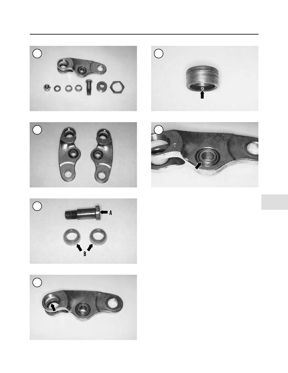
4. Check the spherical ball bearing surfaces (B, Figure
27
) for cracks or excessive wear. If necessary, replace the
bearings as a set.

5. Check the spherical bearing race in the rocker (Figure
28
) and bearing retainer (Figure 29). If necessary, use a
hydraulic press and replace the bearing races as a set. Re-
fer to Chapter One.

6. Check the spherical bearing assembly in the rocker
(Figure 30). If necessary, use a hydraulic press and re-
place the bearing. Refer to Chapter One.

7. Check the bearing retainer jam nut (A, Figure 31) and
bearing retainer (B) for thread damage.

8. Check the spherical bearing in the rocker (Figure 11).
If the Teflon coating is worn completely through at any
point, with the metal surface visible, replace the bearing
as a set as described in this chapter.

Rocker Installation

CAUTION

Be sure to install the fork rockers onto the
correct side of the fork assemblies. The fork
rockers are marked with a

(R)

right side

(

Figure 32

) and

(L)

left side.

FRONT SUSPENSION AND STEERING (SPRINGER FORK)

443

11

25

26

27

28

29

30

1. Thoroughly coat the bearing races with wheel bearing
grease.

NOTE

The spherical surface on each bearing faces
away from each other and toward their re-
spective bearing race.

2. Install the

outer

spherical bearing half into the outer

surface of the fork rocker race (Figure 33). Push it in until
it bottoms (Figure 34).
3. Align the rocker with the rigid fork leg so that it faces
in the normal operating direction (facing forward) (Fig-
ure 35
). Make sure the spherical bearing does not fall out.
4. Install the

inner

spherical bearing half into the inner

surface of the fork rocker race (A, Figure 36). Push it in
until it bottoms.
5. Install the pivot stud (thin head) (B, Figure 36)
through the rigid fork leg, spherical bearings and the other
side of the rocker (Figure 23).
6. Apply ThreeBond TB1342 threadlocking compound
to the pivot stud.
7. Install the washer (Figure 37), acorn nut (FXSTS)
(Figure 38), or hex nut (FLSTS), and washer onto the
pivot stud. Tighten the nut (Figure 39) to 45-50 ft.-lb.
(61-68 N•m).

444

CHAPTER ELEVEN

31

32

33

34

35

36

8. Apply and anti-seize lubricant to the threads of the
bearing retainer (Figure 40). Also, apply a full amount to
the bearing race, then install the bearing retainer (Figure
41
). Tighten the bearing retainer securely at this time.

9. To ensure the spherical bearing are installed correctly,
move the fork rocker up and down at this time (Figure
42
). Check for easy of movement.

10. Install the bearing retainer jam nut.

11. Move the fork rocker up into position on the spring
fork and temporarily install the pivot stud (Figure 43).

FRONT SUSPENSION AND STEERING (SPRINGER FORK)

445

11

37

38

39

40

41

42

43

12. On the rigid fork, tighten the bearing retainer (Figure
44
) to 25-35 in.-lbs. (3-4 N•m).
13. Secure the bearing retainer (A, Figure 45) to keep it
from rotating and tighten the jam nut to (B) 95-105 ft.-lb.
(129-142 N•m).
14. Remove the spring fork pivot stud (Figure 43), in-
stalled in Step 11. Allow the fork rocker to pivot down
away from the spring fork leg.

NOTE

While performing Step 15, check for abnormal
noise or movement that may indicate dam-
aged spherical bearing in the rigid fork leg.

15. Attach a torque wrench onto the rigid fork pivot stud
(Figure 46) and rotate the fork rocker through its arc. The
torque reading should be 25-35 in.-lbs. (3-4 N•m).
16. If the torque reading in Step 11 is out of specification,
readjust the bearing retainer (Step 8) and repeat Step 13.
Repeat until the torque reading is correct.
17. Move the fork rocker into position and install the
spring fork pivot stud (Figure 43) from the inboard side.
Install the washer (Figure 47) and nut (Figure 48);
tighten the nut (Figure 49) to 45-50 ft.-lb. (61-68 N•m).
18. Remove the heavy-duty cable ties from the fork as-
semblies.

446

CHAPTER ELEVEN

44

45

46

47

48

49

19. Repeat for the remaining rocker assembly.
20. On FLSTS models, install the front fender as de-
scribed in Chapter Fourteen.
21. Install the front wheel as described in Chapter Nine.
22. Install the front caliper as described in Chapter Thirteen.

SPRINGER FORK

Removal

Refer to Figure 50 and Figure 51.

The spring fork assembly can be removed from the

rigid fork with the rigid fork installed in the frame. If nec-
essary, the spring and rigid fork can be removed as an as-
sembly as described under

Rigid Fork Removal

in this

chapter.

There are no service specifications for the springs on

this fork assembly. Label each spring as it is removed to
ensure it will be installed on the correct side of the fork.
After removing the springs, compare the two sets of
springs for sag or distortion. If replacement is necessary,
replace the springs as pairs. Take suspected distorted

FRONT SUSPENSION AND STEERING (SPRINGER FORK)

447

11

50

SPRINGER FORK (FXSTS)

1. Acorn nut
2. Washer
3. Spring bridge
4. Spring restraint
5. Rebound spring
6. Spring seat
7. Travel bumper (upper)
8. Bushing
9. Screw

10. Lockwasher
11. Screw
12. Acorn nut
13. Washer
14. Rigid fork
15. Travel bumper (lower)
16. Spring seat
17. Outer compression spring
18. Upper inner

compression spring

19. Spring rod
20. Spring seat
21. Lower inner

compression spring

22. Washer
23. Bolt
24. Shock absorber
25. Acorn nut
26. Special acorn nut
27. Spring fork

springs to a Harley-Davidson dealership and compare to
new springs. The two upper rebound springs and the four
inner and outer compression springs are located between
the rigid and spring fork assemblies. During disassembly,
keep the right and left side components in separate con-
tainers. Parts tend to create a wear pattern after prolonged
use and it is advised to reinstall them in the same location
during assembly.

One special tool is required to safely remove the fork

springs. The Fork Spring Tool from Motion Pro (part No.

08-0144) (Figure 52) is available from a motorcycle
dealership or motorcycle mail order houses. This tool can be
fabricated from hardware store materials as shown in Figure
53
. The block shown at the bottom should be made from
cold-roll steel and the block should be cut so that it can fit be-
tween the shock absorber lower mounting eye on the spring
fork. Then drill the hole through the block with a 3/8 in. drill.

CAUTION

After making the block, round off all corners
with a file to avoid scratching any of the

448

CHAPTER ELEVEN

51

SPRINGER FORK (FLSTS)

1. Acorn nut
2. Washer
3. Spring bridge
4. Spring restraint
5. Rebound spring
6. Spring seat
7. Travel bumper (upper)
8. Bushing
9. Screw

10. Lockwasher
11. Screw
12. Acorn
13. Washer
14. Rigid fork
15. Travel bumper (lower)
16. Spring seat
17. Outer compression spring
18. Upper inner

compression spring

19. Spring rod
20. Spring seat
21. Lower inner

compression spring

22. Washer
23. Bolt
24. Shock absorber
25. Acorn nut
26. Special acorn nut
27. Spring fork

front fork components. Also, remove all
burrs from the drilled hole.

1. Remove the handlebar as described in this chapter.
2. Remove the acorn nuts and washers (A, Figure 54) se-
curing the spring bridge. Remove the spring bridge (B,
Figure 54).
3. Remove the shock absorber as described in this chapter.
4. Remove the headlight assembly as described in Chap-
ter Eight.
5. On FLSTS models, remove the passing lamp assembly
as described in Chapter Eight.
6. Remove the front wheel as described in Chapter Nine.
7. Remove the front brake caliper as described in Chapter
Thirteen.
8. Remove the front fender as described in Chapter Four-
teen.
9. Remove the front fender link as follows:

a. Remove the fender link (Figure 55) from the pivot

shaft on the spring fork.

b. Remove the washer and rubber spacer (Figure 56)

from the pivot shaft on the spring fork.

10. Install the special tool onto the fork as follows:

a. Remove the coupling and washer from the threaded

rod.

FRONT SUSPENSION AND STEERING (SPRINGER FORK)

449

11

52

53

SPRING COMPRESSION TOOL

5/16 in. threaded rod

5/16 in. coupling

Steel and
rubber washers

Jam nut

1 1/2 in.

1 in.

3/8 in. drill

14 1/2 in.

55

54

b. Insert the threaded rod up through the shock ab-

sorber upper mount (A, Figure 57).

c. Insert the block between the lower shock absorber

mount on the spring fork.

d. Secure the block with the shock absorber bolt,

washers and acorn nut (Figure 58).

e. Install the washers and long coupling onto the

threaded rod (B, Figure 57).

11. Measure the distance from the top of the spring rod to
the top of the spring restraint (Figure 59). Record this
measurement since it will be used during assembly.

WARNING

If the spring fork legs are not secured to the
rigid fork legs, the spring pressure will snap
them forward with great force, which could
cause personal injury. The spring fork legs
must be secured with heavy duty cable ties
or an equivalent.

12. Use heavy-duty cable ties, or an equivalent, and secure
each spring fork to the adjacent rigid fork leg. Place the ca-
ble ties close to the boss at the lower end of the spring fork
leg (A, Figure 60). Make sure the cable ties are secure.
13. Remove both rocker arm assemblies (B, Figure 60)
as described in this chapter.

NOTE

The spring seats and travel bumpers are in-
stalled between the rigid fork assembly and
the spring cup at the top of the compression
spring. The compression springs are the
lower springs. The two upper springs are
the rebound springs.

14. Slowly tighten the long coupling with a wrench until
the compression springs bottom out on their spring seats
travel bumpers. This released the pressure on the upper re-
bound springs. Check to make sure the rebound springs
(A, Figure 61) are no longer under pressure. If necessary,
tighten the coupler an additional amount.

450

CHAPTER ELEVEN

56

57

58

59

60

15. Unscrew and remove both spring restraints (B, Fig-
ure 61
).
16. Pull straight up and remove both rebound springs (A,
Figure 61) from the spring rods.
17. Remove the spring seat (A, Figure 62) and the travel
bumper (B) from each spring rod.
18. Slowly loosen the long coupling (B, Figure 57) with
a wrench releasing the tension on the compression springs
(Figure 63).
19. Remove the bushing (Figure 64) from each spring rod.
20. Remove the plastic tie wraps.
21. Secure the spring fork assembly and remove the spe-
cial tool from both fork assemblies.
22. Slide the spring fork assembly down and out of the
rigid fork (Figure 65).

Disassembly

1. Remove the travel bumper (A, Figure 66), spring seat
(B) and outer compression spring (C) from the spring rod.
Remove the travel bumper, spring cup and outer compres-
sion spring from the other spring rod.
2. Remove the inner/upper compression spring (Figure
67
) from the spring rod.
3. Remove the spring rod as follows:

FRONT SUSPENSION AND STEERING (SPRINGER FORK)

451

11

61

62

63

64

65

66

a. Rotate the inner/lower compression spring to allow

access to the cross-hole in the spring rod (Figure 68).

b. Insert a No. 2 Phillips head screwdriver, or drift (A,

Figure 69) through the cross-hole in the spring rod.

c. Secures the spring rod from rotating and loosen the

special acorn nut (B, Figure 69) at the base of the
spring rod.

d. Pull straight up and remove the spring rod assembly

(Figure 70) from the spring fork.

e. Remove the spring seats (A, Figure 71) and in-

ner/lower compression spring (B) from the spring
rod.

f. Repeat for the other spring rod assembly.

CAUTION

The spring rod (C,

Figure 71

) is comprised

of an upper and lower rod assembly. Do not
separate these two rods if either rod is dam-
aged, replace the spring rod as an assembly.

Inspection

Harley-Davidson does not provide any inspection spec-

ifications for the Springer fork assembly. Visually inspect
the components for wear, damage or deterioration. If the
front end was involved in an accident, have the motorcy-
cle inspected by a Harley-Davidson dealership or compe-
tent motorcycle frame specialist.

As noted during removal/disassembly, do not intermix

the right and left side components during the cleaning and
inspection steps. Clean and inspect one set at a time.
1. Clean the travel bumpers in a non-chemical cleaner
like Simple Green all-purpose cleaner. Do not use clean-
ing solvent as some types will cause permanent damage.
2. Clean all remaining components in solvent and dry
with compressed air. Remove all anti-seize lubricant resi-
due from the upper spring rod.
3. Inspect each fork assembly for cracks, bending or
other damage. Check the rocker assembly mounting area

452

CHAPTER ELEVEN

67

68

69

70

71

in both fork assemblies for damage. If either fork assem-
bly is damaged, replace it.
4. Inspect the springs for wear or sag. Compare the right
side spring(s) to the left side spring(s). If there is a differ-
ence in length, replace the springs as a set. Also inspect
the springs for crack or other visual damage.
5. Inspect the spring rod for damage or bending (C, Fig-
ure 71
). Check the threaded portion of each end for thread
damage. Repair with a thread die if necessary. Replace the
spring rod if bent or damaged.
6. Inspect the spring rod spring seats (A, Figure 72) for
cracks or damage where the spring makes contact. Re-
place as a set.
7. Inspect the travel bumpers (B, Figure 72) for hardness
or deterioration.
8. Check the bushing (C, Figure 72) for damage.
9. Inspect the threads in the spring restraints and special
acorn nuts for damage. Repair with thread tap if neces-
sary.
10. Inspect the threads in the spring rod (Figure 73) for
damage. Repair with thread die if necessary.
11. Check the spring bridge for straightness and damage.
12. Inspect the front fender link (Figure 74) for damage.
Check the shoulder bolt bearing surface (A, Figure 75)
and front fender link (B) for damage.

Assembly/Installation

1. Assemble one spring rod at a time as follows:

a. Install the inner/lower compression spring (A, Fig-

ure 76) over the spring rod.

b. Install both spring seats (B, Figure 76) onto the

spring rod to lock the spring in place. Make sure the
spring seats are locked in place on the spring rod
and inserted into the spring.

c. Install the spring rod and inner/lower spring onto

the receptacle on the spring fork (Figure 77).

FRONT SUSPENSION AND STEERING (SPRINGER FORK)

453

11

72

73

74

75

76

d. Install the special acorn nut (Figure 78) onto the

spring rod and tighten finger tight at this time.

e. Rotate the inner/lower compression spring to allow

access to the cross-hole in the spring rod (Figure 68).

f. Insert a No. 2 Phillips head screwdriver, or drift (A,

Figure 69) through the cross-hole in the spring rod.

g. Secure the spring rod from rotating and tighten the

special acorn nut (B, Figure 69) to 20-25 ft.-lb.
(27-34 N•m).

2. Install the inner/upper compression spring (Figure 67)
onto the spring rod.

3. Install the outer compression spring (Figure 79) over the
inner/upper compression spring and onto the spring rod.

4. Correctly position the spring seat with the shoulder
facing down (Figure 80) toward the outer compression
spring and install it.

5. Correctly position the travel bumper with the smaller di-
ameter portion (Figure 81) side going on first and install it
onto the spring rod and into the spring seat (Figure 82).

6. Repeat Steps 1-5 for the other side.

7. Slide the spring fork assembly up and into the rigid
fork (Figure 83). Make sure the lower travel bumpers,
compression spring seats and compression springs prop-
erly engage the bottom of the rigid fork spring brace.

454

CHAPTER ELEVEN

77

78

79

80

81

82

NOTE

Check that both sides of the spring fork are
properly installed into the rigid fork.

8. Have an assistant hold the spring fork in place.
9. Install the special tool onto the fork as follows:

a. Remove the coupling and washer from the threaded

rod.

b. Insert the threaded rod up through the shock ab-

sorber upper mount (A, Figure 84).

c. Insert the block between the lower shock absorber

mount on the spring fork.

d. Secure the block with the shock absorber bolt,

washers and acorn nut (Figure 85).

e. Install the washers and long coupling onto the

threaded rod.

10. Slowly tighten the long coupling (B, Figure 84) with
a wrench until the two outer springs are compressed
enough to secure the spring fork in place.

WARNING

If the spring fork legs are not secured to the
rigid fork legs, the spring pressure will snap
them forward with great force, which could
cause personal injury. The spring fork legs
must be secured with heavy duty cable ties
or an equivalent.

11. Use heavy-duty cable ties, or an equivalent, and secure
each spring fork to the adjacent rigid fork leg. Place the ca-
ble ties close to the boss at the lower end of the spring fork
leg (Figure 86). Make sure the cable ties are secure.
12. Install the rebound springs as follows:

a. Oil the spring rebound bushing and slide it onto the

end of the spring rod. Push the bushing down on the
rod until it bottoms (Figure 64).

b. Install the travel bumper (A, Figure 87) over the

spring rod and onto the bushing.

c. Place the spring seat (B, Figure 87) over the travel

bumper so that it shoulder faces up.

FRONT SUSPENSION AND STEERING (SPRINGER FORK)

455

11

83

84

85

87

86

13. Repeat Step 12 for the other side.
14. Slowly tighten the long coupling (B, Figure 84) with
a wrench until the compression springs bottom out on
their spring seats travel bumpers.
15. Install both rocker arm assemblies (A, Figure 88) as
described in this chapter.
16. Remove the heavy-duty cable ties from the boss at the
lower end of the spring fork leg (B, Figure 88).
17. Make sure the travel bumpers and spring seats are
still in the bottom of the receptacle in the rigid.
18. Position the rebound spring with the tapered spring
end going on last (Figure 89). Install both rebound
springs (A, Figure 90).
19. Apply a coat of anti-seize lubricant to the top 1/2 in.
(12.7 mm) of both spring rod threads.

WARNING

Tighten both spring restraints evenly. Not
having the same amount of exposed spring
rod on each side could adversely affect han-
dling that could lead to loss of control of the
motorcycle.

20. Install the spring restraint (B, Figure 90) onto the
spring rod and tighten it until spring rod protrudes
0.625-0.750 in. (16-19 mm) from the top of the spring re-
strainers (Figure 91).
21. Repeat Steps 19-21 for the other spring restraint
maintaining the same distance of 0.625-0.750 in. (16-19
mm).
22. Remove the special tool.
23. Install the shock absorber as described in this chapter.
24. Correctly position the headlight electrical wire be-
hind the rebound springs.
25. Install the acorn nuts (A, Figure 92) and spring
bridge (B). Tighten the acorn nuts to 30-35 ft.-lb. (41-48
N•m).
26. Install the front fender link as follows:

a. Install the rubber washer (Figure 93) and washer

(Figure 94) onto the pivot shaft on the spring fork.

b. Install the fender link (Figure 95) onto the pivot

shaft on the spring fork. Push it on until it bottoms.

27. Install the handlebar as described in Chapter Ten.
28. Install the front fender as described in Chapter Four-
teen.
29. Install the front brake caliper as described in Chapter
Thirteen.
30. Install the front wheel as described in Chapter Nine.
31. On FLSTS models, install the passing lamp assembly
as described in Chapter Eight.
32. Install the headlight assembly as described in Chapter
Eight.

456

CHAPTER ELEVEN

88

89

90

91

33. Lower the motorcycle to the ground and place it on
the jiffy stand.
34. Apply the front brake and compress the front suspen-
sion several times and make sure there is no binding or ab-
normal noise.
35. Test ride the motorcycle slowly at first to make sure
the front suspension is operating correctly.

WARNING

Do not ride the motorcycle until the front
brake is operating correctly with full hy-
draulic advantage and that the front suspen-
sion is operating correctly.

RIGID FORK

Removal

Refer to Figure 96 and Figure 97.
The rigid fork can be removed with the spring fork at-

tached to it. This procedure outlines the removal of the
rigid fork with the spring fork attached or removed.
1. Remove the shock absorber as described in this chap-
ter.
2. Loosen the upper bracket clamp bolt (Figure 98).
3. Remove the headlight assembly (A, Figure 99) as de-
scribed in Chapter Eight.
4. On FLSTS models, remove the passing lamp assembly
as described in Chapter Eight.
5. Remove the front wheel as described in Chapter Nine.
6. Remove the front brake caliper as described in Chapter
Thirteen.
7. Remove the front fender as described in Chapter Four-
teen.
8. Remove the handlebar and risers (B, Figure 99) as de-
scribed in this chapter.
9. If necessary, remove the spring fork as described in
this chapter.
10. Remove the bolt and bracket (Figure 100) securing
the front brake line to the side of the rigid fork.
11. Remove the bolt and bracket (Figure 101) securing
the front brake line to the base of the rigid fork below the
steering stem.
12. Loosen and remove the fork stem acorn nut and rub-
ber washer (C, Figure 99).
13. Loosen and remove both rigid fork leg studs.
14. Remove the upper bracket.

NOTE

The rigid fork assembly can fall out of the
steering head after the bearing retainer is

FRONT SUSPENSION AND STEERING (SPRINGER FORK)

457

11

93

94

95

92

458

CHAPTER ELEVEN

96

RIGID FORK AND STEERING STEM (FXSTS)

1. Bolt
2. Clamp
3. Ground spring
4. Locknut
5. Washer
6. Rubber bushing
7. Riser
8. Rubber bushing
9. Threaded stud

10. Acorn nut
11. Washer
12. Upper bracket
13. Bearing retainer

14. Dust shield
15. Upper bearing
16. Upper bearing race
17. Steering head/frame
18. Grease fitting
19. Steering lock
20. Lower bearing race
21. Lower bearing
22. Dust shield
23. Rigid fork
24. Steering stem
25. Snap ring


Content      ..     24      25      26      27     ..