Harley Davidson Softail 2000-2005. Service manual - page 30
 

  Главная      Harley Davidson     Harley Davidson Softail 2000-2005. Service manual


Search            copyright infringement  


Content      ..     28      29      30      31     ..


Harley Davidson Softail 2000-2005. Service manual - page 30


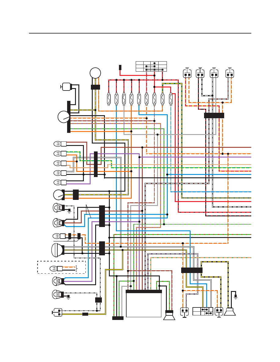
622

WIRING DIAGRAMS

Turn signal/

Security module

(TSM/TSSM)

Fuel

gauge

154

21

Neutral

High beam

Front

fender

tip light

Left turn

signal

Right turn

signal

Oil

pressure

Headlight

Domestic only

Right

passing

light

Left

passing

light

Right

front turn

signal

Left

front turn

signal

Left

turn signal

switch

Emergency

stop

switch

Starter

switch

74

117

73

31

32

DOM only

143

38

Lights

15A

Instr

15A

Acc

15A

ECM

15A

Fuel

pump

15A

Batter

y

15A

Ign.

15A

Right

turn signal

switch

Function/

tripmeter

reset switch

Passing

lights

switch

Horn

142

122

24

22

Siren

(optional)

Horn

switch

Front

brake

switch

B+ connector

10A max

Headlight

dimmer switch

High

Low

30

Ignition

2

Vss/serial

data

link

3

Security

indicator

4

Right

turn

feed

6

Left

turn

feed

5

Gr

ound

12

Alarm

signal

11

Ignition

enab

le

sig

10

Star

t

rela

y

contr

ol

9

Left

turn

s

w

input

8

Right

turn

s

w

input

7

Batter

y

1

Fuel pump/

Sender

86

Speedometer

Data link

91

Headlight

15A

P

& A Ign.

2A

Off

Acc

Ign

Ignition switch

33

160

39

Position

light

To 38

HDI model only

2004-2005 ALL DOMESTIC AND HDI SOFTAIL MODELS

WIRING DIAGRAMS

623

17

Neutral

indicator

switch

Oil

pressure

switch

85

84

Gnd 3

Gnd

1 & 2

Battery

Spark

plugs

Crank

position

sensor

79

121

120

131

Diagram Key

Connectors

Ground (Gnd)

Frame ground

No connection (NC)

Connection

Rear

brake

switch

46

62

128

Stator

Ignition

coil

Starter

solenoid/

Motor

Starter

relay

78

F

an

output

2

T

ac

h

output

3

System

rela

y

4

Engine

temp.

6

Serial

data

link

5

Idle

air

contr

ol

36

Idle

air

contr

ol

18

Idle

air

contr

ol

35

Idle

air

contr

ol

17

Digital

po

wer

NC 34

Frequenc

y

input

NC 16

Digital

gr

ound

NC 15

5V

sensor

po

wer

14

Switc

h

po

wer

13

Speed

sensor

input

33

Constant

po

wer

31

CKP

sensor

30

CKP

sensor

12

Coil,

fr

ont

29

Coil,

rear

11

P

o

wer

gr

ound

10

Analog

input/

NC

9

O2

sensor

input

NC

8

Intake

air

temp.

7

P

o

wer

gr

ound

28

Ion

sense

27

5V

sensor

gr

ound

26

MAP

sensor

input

25

TPS

input

24

Analog/O2

input

NC 23

HDI

solenoid

NC 22

Injector

,

fr

ont

21

Injector

,

rear

19

Output

NC/

20

Switc

h

input

NC 32

Flash

pin

1

ECM

System

relay

Circuit

breaker

30A

Rear fuel
injector

See detail for tail/brake light,
rear turn signals, fender tip,
position and license lights
circuit wiring

Front fuel
injector

Engine

temp.

sensor

80

90

89

Intake air

temp.

sensor

88

Throttle

position

sensor

7

87

Idle air

control

Voltage

regulator

83

a

86 85

87

30

87

a

86 85

87

30

87

Speed

sensor

65

B Ion sen

Coil rear

Coil frt

A pwr

C

D

Manifold

air press.

Sensor (MAP)

624

WIRING DIAGRAMS

Turn signal/

Security module

(TSM/TSSM)

Fuel

gauge

154

21

Neutral

High beam

Left turn

signal

Right turn

signal

Oil

pressure

Headlight

Domestic only

Right

passing

light

Right

front turn

signal

Left

turn signal

switch

Emergency

stop

switch

Starter

switch

117

31

32

143

38

Lights

15A

Instr

15A

Acc

15A

Batter

y

15A

Ign.

15A

Right

turn signal

switch

Function/

tripmeter

reset switch

Horn

142

122

24

22

Siren

(optional)

Horn

switch

Front

brake

switch

B+ connector

10A max

Headlight

dimmer switch

High

Low

30

Ignition

2

Vss/serial

data

link

3

Security

indicator

4

Right

turn

feed

6

Left

turn

feed

5

Gr

ound

12

Alarm

signal

11

Ignition

enab

le

sig

10

Star

t

rela

y

contr

ol

9

Left

turn

s

w

input

8

Right

turn

s

w

input

7

Batter

y

1

Fuel sender

(in tank)

86

Speedometer

Data link

91

Headlight

15A

P

& A Ign.

2A

Off

Acc

Ign

Ignition switch

33

160

39

Front

fender

tip light

Left

passing

light

Left

front turn

signal

74

73

Passing

lights

switch

Position

light

To 38

HDI model only

DOM only

2004-2005 ALL DOMESTIC AND HDI CARBURETED SOFTAIL MODELS

WIRING DIAGRAMS

625

17

Neutral

indicator

switch

Oil

pressure

switch

Gnd 3

Gnd

1 & 2

Battery

Spark

plugs

121

120

131

Rear

brake

switch

46

61

128

Stator

Ignition

coil

Starter

solenoid/

Motor

Circuit
breaker
30A

Manifold

Air Press

sensor (MAP)

80

83

Voltage

regulator

Starter

relay

a

86 85

87

30

87

Batter

y

2

+5V

sensor

po

wer

3

Sensor

gr

ound

4

Coil

fr

ont

6

Module

gr

ound

5

Serial

data

12

Map

signal

11

V

ehic

le

speed

signal

10

Crank

sensor

(-)

9

Crank

sensor

(+)

8

Coil

rear

7

Run/Stop

signal

1

10

Ignition control module

(ICM)

Speed

sensor

65

Crank

position

sensor

79

B (power)

A (rear)

C (front)

Diagram Key

Connectors

Ground (Gnd)

Frame ground

No connection (NC)

Connection

See detail for tail/brake light,
rear turn signals, fender tip,
position and license lights
circuit wiring

7

626

WIRING DIAGRAMS

2004-2005

Taillight circuit

All models except FXSTD AND FLSTS

Left
rear turn
signal

19

32

93

94

18

Fender tip
light for US
FLSTC only

Tail
light

Right
rear turn
signal

Running

light (HDI)

Running

light (DOM)

Note:
The violet and brown wires are transposed
in connector 94 on the FXST/S/B inverted
tail light mount.

7

Gnd 3

2005

Taillight circuit

FLSTSC/FLSTN models

Left
rear turn
signal

18

93

19

Gnd 3

Tail/
brake
light

HDI only

Right
rear turn
signal

7

2004-2005

Taillight circuit

FXSTD AND FLSTS

Gnd 3

Left
rear turn
signal

18

45

32

93

19

Fender tip
light for US
FLSTC only

Tail
light

HDI only

Right
rear turn
signal

License
plate lights
(FXSTD only)

7

7. Disconnect the vent line (Figure 109) from the fitting
on the front of the fuel tank.

8A. On FXSTDI models, remove the nut and washer se-
curing the rear of the fuel tank to the frame.

8B. On all models except FXSTDI, remove the Torx bolt
and washer (Figure 110) securing the rear of the fuel tank
to the frame.

9. At the front of the fuel tank, remove the acorn nut and
washers from the through bolt (Figure 111). Withdraw the
through bolt from the left side securing the fuel tank to the
frame.

FUEL, EXHAUST AND EMISSION CONTROL SYSTEMS

299

7

106

FUEL TANK (ALL EFI MODELS EXCEPT FXSTDI)

1. Screw
2. Washer
3. Screw
4. Washer
5. Fuel filler cap
6. Gasket
7. Grommet (upper)
8. Grommet (lower)
9. T-nut

10. Fuel tank
11. Rubber trim piece
12. Drain screw
13. Hose clamp
14. O-ring
15. Fuel tank plug
16. Check valve and hose
17. Acorn nut
18. Washer
19. Bolt
20. Retaining ring
21. Screw
22. Bushing
23. Grommet
24. Tie-wrap
25. Hose clamp
26. Crossover hose

assembly

27. Vent line

(fuel tank to vapor valve)

28. Vapor valve
29. Hose clamp
30. Hose
31. Screw
32. Bracket (vapor valve)
33. Fuel line
34. Hose reduction fitting

107

10. Lift and remove the fuel tank (Figure 112).
11. Inspect the fuel line quick-disconnect fitting for signs
of leaks. Replace as necessary.
12. Drain any remaining fuel left in the tank into a gas can.
13. Inspect the fuel tank as described in this chapter.

WARNING

Store the fuel tank in a safe place away from
open flames or where it could be damaged.

14. Installation is the reverse of these steps while noting
the following:

a. Tighten the front and rear bolts and nuts to the spec-

ification in Table 2.

b. Reconnect the fuel line quick–disconnect fitting

(Figure 113) onto the fuel tank until it clicks into
the locked position. Pull down on the fuel line to
make sure it is secured.

c. On all models except FXSTDI, make sure the vent

line runs along the right side of the frame backbone
under the rubber trim.

d. Refill the tank and check for leaks.

FUEL TANK INSPECTION (ALL MODELS)

1. Inspect the fuel hoses (A, Figure 114) and vent hoses
for cracks, deterioration or damage. Replace damaged
hoses with the same type and size materials. The fuel lines
must be flexible and strong enough to withstand engine
heat and vibration.
2. Check the fuel line insulator(s) for damage.
3. Check for damaged fuel tank mounting brackets. Refer
to Figure 115 and B, Figure 114.
4. Make sure the fuel level gauge wiring harness clamp is
tight (Figure 116).
5. On fuel injected models, check the quick disconnect
fitting (A, Figure 117) for tightness and fuel leakage.
6. On all models, check the fuel tank plug (B, Figure
117
) for tightness and fuel leakage.

300

CHAPTER SEVEN

108

109

110

111

112

7. Remove the filler cap and inspect the tank for rust or
contamination. If there is a rust buildup inside the tank,
clean and flush the tank as described in this chapter.
8. Inspect the fuel tank for leaks.

FUEL PUMP AND FUEL FILTER

(EFI MODELS)

Refer to Figure 118.

Top Plate Assembly Removal/Installation

1. Depressurize the fuel system as described in this chapter.
2. Remove the seat as described in Chapter Fourteen.
3. Remove the fuel tank console as described in this
chapter.
4. Drain the fuel tank as described in this chapter.
5. Remove the ten screws securing the top plate (Figure
119
) to the top of the fuel tank. Discard the screws.
6. Partially lift the top plate up away from the fuel tank.

CAUTION

Do not cut the fuel supply hose while cutting
the hose clamp in the following step.

7. On the right side of the fuel tank, carefully cut the hose
clamp securing the outlet hose to the fuel filter fitting.
8. Carefully pull the top plate assembly straight up and
out of the fuel tank. Do not damage the fuel gauge sending
unit float during removal.
9. Remove the top plate gasket.
10. Installation is the reverse of these removal steps
while noting the following:

a. Raise the float to the up (FULL) position and install

the assembly until the rubber spacer rests on the
bottom of the fuel tank.

b. Slip a

new

hose clamp onto the outlet hose prior to

installing the assembly into the fuel filter fitting.

FUEL, EXHAUST AND EMISSION CONTROL SYSTEMS

301

7

114

115

116

117

113

302

CHAPTER SEVEN

118

FUEL PUMP, FILTER AND LEVEL GAUGE

(EFI MODELS)

11. Pressure regulator
12. Pressure regulator

housing

13. Fuel filter
14. Bail
15. Connector clip
16. Bail bracket
17. Hose clamp
18. O-ring
19. Rubber sleeve
20. Pin terminal
21. Socket terminal

22. End cap
23. Cable strap
24. Spring
25. Fuel pump
26. Fuel pump housing
27. Rubber cushion
28. Rubber spacer
29. Gasket
30. Screw
31. Fuel level sending

unit and harness

1. Top plate (FXSTDI)
2. Gasket (FXSTDI)
3. Fuel level gauge
4. Gasket
5. Electrical connector—

fuel pump modulator

6. Fuel hose
7. Screw
8. Top plate

(all models except FXSTDI)

9. Socket terminal

10. O-ring

c. Install the outlet onto the fuel filter fitting and crimp

the hose clamp.

d. Pivot the top plate and push down so the end cap en-

gages the fuel pump housing.

e. Install a

new

top plate gasket.

f. Install

new

screws securing the top plate and tighten

securely.

Fuel Filter Removal/Installation

1. Remove the top plate assembly as previously de-
scribed in this chapter.

2. Carefully pull the wire bail from the slots on the fuel
filter canister bracket. Move the wire bail out of the way.

3. Carefully pull the fuel filter out of the pressure regula-
tor housing.

4. Use side cutting pliers to cut the hose clamp and re-
move it from the fuel filter hose.

5. Disconnect the fuel filter from the fuel pump hose.

6. Discard the fuel pump.

7. Installation is the reverse of removal while noting the
following:

a. Use a

new

hose clamp.

b. Use a

new

O-ring on the fuel filter.

Fuel Pressure Regulator
Removal/Installation

1. Remove the fuel filter from the fuel pressure regulator.

2. Slide the fuel pressure regulator assembly forward to
free its arms from the top plate.

3. Use a rocking motion and remove the fuel pressure
regulator from the housing.

4. Installation is the reverse of removal. Apply clean en-
gine oil to the new fuel pressure regulator O-rings.

Fuel Pump
Removal/Installation

NOTE

During the removal procedure, the fuel
pump mounting bracket will be damaged
and must be replaced along with the fuel
pump. Make sure the fuel pump is defective
prior to removing it from the bracket.

1. Remove the top plate assembly as previously de-
scribed in this chapter.
2. Depress the external latch and disconnect the electrical
connector from the fuel pump.
3. Use side cutting pliers to cut the hose clamp, and re-
move it from the fuel pump hose.
4. Remove the screw and remove the fuel level sending
unit from the post on the fuel pump mounting bracket.
5. Disconnect the spring from the hook on the fuel pump
mounting bracket.
6. Insert a flat screwdriver tip and crack the webbing at
top of the fuel pump mounting bracket hinge. Remove the
hinge from the mounting bracket.
7. Remove and discard the fuel pump and bracket assembly.
8. Installation is the reverse of removal while noting the
following:

a. Use a

new

hose clamp.

b. Install a new fuel pump and fuel pump mounting

bracket.

FUEL SHUTOFF VALVE

(CARBURETED MODELS)

A three-way vacuum-operated fuel shutoff valve is

mounted to the left side of the fuel tank. A replaceable fuel
filter is mounted to the top of the fuel shutoff valve.

To troubleshoot this valve, refer to

Vacuum Operated

Fuel Shutoff Valve Testing

in Chapter Two.

Removal

WARNING

Gasoline is very volatile and flammable.
Work in a well-ventilated area away from
any open flames, including pilot lights on
household appliances. Do not allow anyone
to smoke in the area and have a fire extin-
guisher rated for gasoline fires on hand.

1. Disconnect the negative battery cable as described in
Chapter Eight.
2. Turn the fuel shutoff valve to the OFF position.

FUEL, EXHAUST AND EMISSION CONTROL SYSTEMS

303

7

119

3. Drain the fuel tank as described under

Fuel Tank Re-

moval/Installation

in this chapter.

NOTE

The fuel shutoff valve can be removed with
the fuel tank in place.

Figure 120

is shown

with the fuel tank removed to better illus-
trate the step.

4. Loosen the fuel valve fitting (A, Figure 120) and re-
move the fuel shutoff valve (B) from the fuel tank. Drain
residual gasoline still in the tank after the valve is re-
moved.

Cleaning and Inspection

1. Inspect the filter mounted on top of the fuel valve. Re-
move contamination from the filter. Replace the filter if it
is damaged.
2. Install a

new

filter gasket before installing the filter

onto the fuel valve.
3. Remove all sealant residue from the fuel tank and fuel
valve threads.

Installation

1. Install a

new

filter gasket onto the fuel shutoff valve,

then install the filter.
2. Coat the fuel valve threads with Loctite Teflon pipe
sealant.
3. Insert the fuel valve into the tank, then start the hex fit-
ting onto the fuel tank threads two turns.
4. Hold the hex fitting and start the fuel valve into the fit-
ting by turning it

counterclockwise

two turns.

5. Hold the fuel valve and tighten the hex fitting to 15-20
ft. lb. (20-27 N•m).

WARNING

If the hex fitting is turned more than two
turns on the valve, it may bottom out on the
valve and cause a fuel leak.

6. Install the insulator tube over the fuel hose.
7. Reconnect the fuel hose to the fuel shutoff valve and
secure it with a hose clamp.
8. Refill the fuel tank and check for leaks.

FUEL TANK GAUGE

WARNING

Gasoline is extremely flammable and explo-
sive, perform this procedure away from all
open flames, including appliance pilot

lights, and sparks. Do not smoke or allow
someone to smoke in the work area, as an
explosion and fire may occur. Always work
in a well-ventilated area. Wipe up any spills
immediately.

2000 Models (Except FXSTD)
Removal/Installation

Refer to Figure 121.

1. Remove the seat as described in Chapter Fourteen.
2. Disconnect the negative battery cable as described in
Chapter Eight.
3. Remove the fuel tank as described in this chapter.

NOTE

The fuel gauge sending unit electrical wires
are routed through a tube in the fuel tank
and are secured with a clamp at the bottom
of the fuel tank. Loosen the clamp (

Figure

116

) and make sure there is enough slack in

the wires to allow the gauge to be pulled up
and out of the fuel tank.

4. To remove the fuel gauge only, perform the following:

CAUTION

Do not twist the fuel gauge in Step 4 as the
fuel gauge will be damaged.

a. Carefully pull straight up and partially withdraw the

fuel gauge from the fuel tank.

b. Mark the wire connectors and the terminal on the

fuel gauge to ensure correct installation.

c. Disconnect the electrical connectors from the back

of the fuel gauge. Do not disconnect the wires from
the sending unit.

d. Remove the fuel gauge and gasket.

5. To remove the fuel gauge sending unit, perform the
following:

304

CHAPTER SEVEN

120

a. Remove the fuel gauge as described in Step 4.
b. Remove the screws securing the sending unit to the

fuel tank.

c. Disconnect the sending unit electrical connector

from the wires in the fuel tank.

CAUTION

Do not bend the float arm during removal of
the sending unit. If bent, the gauge will give
inaccurate readings.

d. Carefully withdraw the sending unit while moving

it back and forth, and while lifting and turning it in
either direction.

e. Remove the gasket from the fuel tank.

6. Install by reversing these removal steps while noting
the following:

a. Install

new

gaskets between the fuel gauge and fuel

tank.

b. Install the sending unit

carefully

to avoid damage to

the float arm.

c. Tighten all screws securely.

2000-on FXSTD Models
Removal/Installation

Refer to Figure 122.

1. Remove the seat as described in Chapter Fourteen.
2. Disconnect the negative battery cable as described in
Chapter Eight.
3. Remove the fuel tank as described in this chapter.

NOTE

The fuel gauge sending unit electrical wires
are routed through a tube in the fuel tank
and are secured with a clamp at the bottom
of the fuel tank. Loosen the clamp (

Figure

116

) and make sure there is enough slack in

the wires to allow the gauge to be pulled up
and out of the fuel tank.

4. To remove the fuel gauge only, perform the following:

CAUTION

Do not twist the fuel gauge in Step 4 as the
fuel gauge will be damaged.

a. Carefully pull straight up and partially withdraw the

fuel gauge from the fuel tank.

b. Mark the wire connectors and the terminal on the

fuel gauge to ensure correct installation.

c. Disconnect the electrical connectors from the back

of the fuel gauge. Do not disconnect the wires from
the sending unit.

d. Remove the fuel gauge and gasket.

5. To remove the fuel gauge sending unit, perform the
following:

a. Remove the fuel gauge as described in Step 4.
b. Disconnect the electrical harness from the connec-

tor (A, Figure 123) on the top plate.

c. Remove the T20 Torx screws (B, Figure 123) se-

curing the top plate.

CAUTION

Do not bend the float arm during removal of
the sending unit. If bent, the gauge will give
inaccurate readings.

FUEL, EXHAUST AND EMISSION CONTROL SYSTEMS

305

7

121

FUEL LEVEL SENDING UNIT

(2000 MODELS EXCEPT FXSTD)

1. Fuel level gauge
2. Bulb
3. Gasket
4. Screw
5. Sending unit
6. Gasket
7. Wiring harness
8. Clip


Content      ..     28      29      30      31     ..