Harley Davidson Softail 2000-2005. Service manual - page 3
 

  Главная      Harley Davidson     Harley Davidson Softail 2000-2005. Service manual


Search            copyright infringement  


Content      ..     1      2      3      4      ..


Harley Davidson Softail 2000-2005. Service manual - page 3


BASIC TOOLS

Most of the procedures in this manual can be carried out

with simple hand tools and test equipment familiar to the
home mechanic. Always use the correct tools for the job at
hand. Keep tools organized and clean. Store them in a tool
chest with related tools organized together.

Some of the procedures in this manual specify special

tools. In most cases, the tool is illustrated in use.
Well-equipped mechanics may be able to substitute simi-
lar tools or fabricate a suitable replacement. In some
cases, specialized equipment or expertise may make it im-
practical for the home mechanic to attempt the procedure.
Such operations are identified in the text with the recom-
mendation to have a dealership or specialist perform the
task. It may be less expensive to have a professional per-
form these jobs, especially when considering the cost of
the equipment.

Quality tools are essential. The best are constructed of

high-strength alloy steel. These tools are light, easy to use
and resistant to wear. Their working surface is devoid of
sharp edges and the tool is carefully polished. They have
an easy-to-clean finish and are comfortable to use. Qual-
ity tools are a good investment.

When purchasing tools to perform the procedures cov-

ered in this manual, consider the tool’s potential frequency
of use. If starting a tool kit, consider purchasing a basic tool
set (

Figure 13

) from a large tool supplier. These sets are

available in many tool combinations and offer substantial
savings when compared to individually purchased tools.
As work experience grows and tasks become more compli-
cated, specialized tools can be added.

The models covered in this manual use both U.S. Stan-

dard and metric fasteners. Make sure the correct type of
tool is used.

Screwdrivers

Screwdrivers of various lengths and types are manda-

tory for the simplest tool kit. The two basic types are the
slotted tip (flat blade) and the Phillips tip. These are avail-
able in sets that often include an assortment of tip sizes
and shaft lengths.

As with all tools, use a screwdriver designed for the job.

Make sure the size of the tip conforms to the size and
shape of the fastener. Use them only for driving screws.
Never use a screwdriver for prying or chiseling metal. Re-
pair or replace worn or damaged screwdrivers. A worn tip
may damage the fastener, making it difficult to remove.

Torx Drivers

Many of the components on the Harley-Davidson models

covered in this manual are secured with internal Torx fasten-
ers. These fasteners require specific Torx drivers for removal
and installation. These fasteners reduce cam-out and fastener
damage, and allow high torque transmission due to the com-
plete enclosure of the driver within the fastener.

Torx screwdrivers in individual sizes, or screwdrivers that

accept various bit sizes are available. However, the most
practical application is a Torx bit set that accepts various
drive types and sizes. A typical set contains T-10 through
T40 bits that accept 1/4 and 3/8 in. drive attachments.

Wrenches

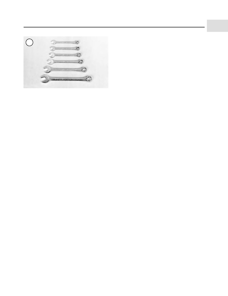
Open-end, box-end and combination wrenches (

Figure

14

) are available in a variety of types and sizes.

The number stamped on the wrench refers to the dis-

tance between the work areas. This size must match the
size of the fastener head.

The box-end wrench is an excellent tool because it grips

the fastener on all sides. This reduces the chance of the
tool slipping. The box-end wrench is designed with either
a 6- or 12-point opening. For stubborn or damaged fasten-
ers, the 6-point provides superior holding ability by con-
tacting the fastener across a wider area at all six edges. For
general use, the 12-point works well. It allows the wrench
to be removed and reinstalled without moving the handle
over such a wide arc.

An open-end wrench is fast and works best in areas with

limited overhead access. It contacts the fastener at only
two points, and is subject to slipping under heavy force, or
if the tool or fastener is worn. A box-end wrench is pre-
ferred in most instances, especially when breaking a fas-
tener loose and applying the final tightness to a fastener.

GENERAL INFORMATION

9

1

14

The combination wrench has a box-end on one end and

an open-end on the other. This combination makes it a
very convenient tool.

Adjustable Wrenches

An adjustable wrench or Crescent wrench (

Figure 15

)

can fit nearly any nut or bolt head that has clear access
around its entire perimeter. Adjustable wrenches are best
used as a backup wrench to keep a large nut or bolt from
turning while the other end is being loosened or tightened
with a box-end or socket wrench.

Adjustable wrenches contact the fastener at only two

points, which makes them more subject to slipping off the
fastener. The fact that one jaw is adjustable and may
loosen only aggravates this shortcoming. Make certain
the solid jaw is the one transmitting the force.

Socket Wrenches, Ratchets and Handles

Sockets that attach to a ratchet handle (

Figure 16

) are

available with 6-point (A,

Figure 17

) or 12-point (B)

openings and different drive sizes. The drive size indi-
cates the size of the square hole that accepts the ratchet
handle. The number stamped on the socket is the size of
the work area and must match the fastener head.

As with wrenches, a 6-point socket provides superior

holding ability, while a 12-point socket needs to be moved
only half as far to reposition it on the fastener.

Sockets are designated for either hand or impact use.

Impact sockets are made of thicker material for more du-
rability. Compare the size and wall thickness of a 19-mm
hand socket (A,

Figure 18

) and the 19-mm impact socket

(B). Use impact sockets when using an impact driver or
air tools. Use hand sockets with hand-driven attachments.

WARNING

Do not use hand sockets with air or impact
tools as they may shatter and cause injury.
Always wear eye protection when using im-
pact or air tools.

Various handles are available for sockets. The speed

handle is used for fast operation. Flexible ratchet heads in
varying lengths allow the socket to be turned with varying
force, and at odd angles. Extension bars allow the socket
setup to reach difficult areas. The ratchet is the most ver-
satile. It allows the user to install or remove the nut with-
out removing the socket.

Sockets combined with any number of drivers make

them undoubtedly the fastest, safest and most convenient
tool for fastener removal and installation.

10

CHAPTER ONE

16

17

18

15

Impact Driver

An impact driver provides extra force for removing fas-

teners by converting the impact of a hammer into a turn-
ing motion. This makes it possible to remove stubborn
fasteners without damaging them. Impact drivers and in-
terchangeable bits (

Figure 19

) are available from most

tool suppliers. When using a socket with an impact driver,
make sure the socket is designed for impact use. Refer to

Socket Wrenches, Ratchets and Handles

in this section.

WARNING

Do not use hand sockets with air or impact
tools as they may shatter and cause injury.
Always wear eye protection when using im-
pact or air tools.

Allen Wrenches

Allen or setscrew wrenches (

Figure 20

) are used on fas-

teners with hexagonal recesses in the fastener head. These
wrenches are available in L-shaped bar, socket and T-han-
dle types. Most motorcycles are equipped with metric fas-
teners. Allen bolts are sometimes called socket bolts.

Torque Wrenches

A torque wrench (

Figure 21

) is used with a socket,

torque adapter or similar extension to tighten a fastener to a
measured torque. Torque wrenches come in several drive
sizes (1/4, 3/8, ½ and 3/4) and have various methods of
reading the torque value. The drive size indicates the size of
the square drive that accepts the socket, adapter or exten-
sion. Common methods of reading the torque value are the
deflecting beam, the dial indicator and the audible click .

When choosing a torque wrench, consider the torque

range, drive size and accuracy. The torque specifications
in this manual indicate the range required.

A torque wrench is a precision tool that must be properly

cared for to remain accurate. Store torque wrenches in cases
or separate padded drawers within a toolbox. Follow the
manufacturer’s instructions for their care and calibration.

Torque Adapters

Torque adapters or extensions extend or reduce the

reach of a torque wrench. The torque adapter shown in

Figure 22

is used to tighten a fastener that cannot be

reached due to the size of the torque wrench head, drive
and socket. If a torque adapter changes the effective lever
length (

Figure 23

), the torque reading on the wrench will

not equal the actual torque applied to the fastener. It is nec-

GENERAL INFORMATION

11

1

19

20

21

22

essary to recalibrate the torque setting on the wrench to com-
pensate for the change of lever length. When a torque adapter
is used at a right angle to the drive head, calibration is not re-
quired since the effective length has not changed.

To recalculate a torque reading when using a torque

adapter, use the following formula and refer to

Figure 23

.

TW = TA ×L

L + A

TW is the torque setting or dial reading on the wrench.

TA is the torque specification and the actual amount of

torque that will be applied to the fastener.

A is the amount that the adapter increases (or in some

cases reduces) the effective lever length as measured
along the centerline of the torque wrench.

L is the lever length of the wrench as measured from the

center of the drive to the center of the grip.

The effective length is the sum of L and A.
Example:
TA = 20 ft.-lb.
A = 3 in.
L = 14 in.
TW = 20 ×14 = 280 = 16.5 ft. lb.

14 + 3

17

12

CHAPTER ONE

23

L

A

L

L

A

L + A = Effective length

L = Effective length

No calculation needed

L

HOW TO MEASURE TORQUE WRENCH EFFECTIVE LENGTH

In this example, the torque wrench would be set to the

recalculated torque value (TW = 16.5 ft.-lb.) . When using
a beam-type wrench, tighten the fastener until the pointer
aligns with 16.5 ft.-lb. In this example, although the
torque wrench is pre-set to 16.5 ft.-lb., the actual torque is
20 ft.-lb.

Pliers

Pliers come in a wide range of types and sizes. Pliers are

useful for holding, cutting, bending and crimping. Do not

use them to turn fasteners.

Figure 24

show several types

of useful pliers. Each design has a specialized function.
Slip-joint pliers are general-purpose pliers used for grip-
ping and bending. Diagonal cutting pliers are needed to
cut wire and can be used to remove cotter pins.
Needlenose pliers are used to hold or bend small objects.
Locking pliers (

Figure 25

), sometimes called Vise-grips,

are used to hold objects very tightly. They have many uses
ranging from holding two parts together, to gripping the
end of a broken stud. Use caution when using locking pli-
ers, as the sharp jaws will damage the objects they hold.

Snap Ring Pliers

Snap ring pliers are specialized pliers with tips that fit

into the ends of snap rings to remove and install them.

Snap ring pliers are available with a fixed action (either

internal or external) or convertible (one tool works on
both internal and external snap rings). They may have
fixed tips or interchangeable ones of various sizes and an-
gles. For general use, select a convertible type pliers with
interchangeable tips.

WARNING

Snap rings can slip and fly off when they are
being removed and installed. Also, the snap
ring pliers tips may break. Always wear eye
protection when using snap ring pliers.

Hammers

Various types of hammers (

Figure 26

) are available to

fit a number of applications. A ball-peen hammer is used
to strike another tool, such as a punch or chisel. Soft-faced
hammers are required when a metal object must be struck
without damaging it.

Never

use a metal-faced hammer on

engine and suspension components, as damage will occur
in most cases.

Always wear eye protection when using hammers.

Make sure the hammer face is in good condition and the
handle is not cracked. Select the correct hammer for the
job and make sure to strike the object squarely. Do not use
the handle or the side of the hammer to strike an object.

SPECIAL TOOLS

Many of the procedures in this manual require special

tools. These are described in the appropriate chapter and
are available from either the manufacturer or a tool sup-
plier. See

Table 12

.

In many cases, an acceptable substitute may be found in

an existing tool kit. Another alternative is to make the

GENERAL INFORMATION

13

1

25

26

24

tool. Many schools with a machine shop curriculum wel-
come outside work that can be used as practical shop ap-
plications for students.

PRECISION MEASURING TOOLS

The ability to accurately measure components is essen-

tial to successful service and repair. Equipment is manu-
factured to close tolerances, and obtaining consistently
accurate measurements is essential to determining which
components require replacement or further service.

Each type of measuring instrument is designed to mea-

sure a dimension with a certain degree of accuracy and
within a certain range. When selecting the measuring tool,
make sure it is applicable to the task.

As with all tools, measuring tools provide the best re-

sults if cared for properly. Improper use can damage the
tool and result in inaccurate results. If any measurement is
questionable, verify the measurement using another tool.
A standard gauge is usually provided with measuring
tools to check accuracy and calibrate the tool if necessary.

Precision measurements can vary according to the ex-

perience of the person performing the procedure. Accu-
rate results are only possible if the mechanic possesses a
feel for using the tool. Heavy-handed use of measuring
tools will produce less accurate results. Hold the tool
gently by the fingertips so the point at which the tool con-
tacts the object is easily felt. This feel for the equipment
will produce more accurate measurements and reduce the
risk of damaging the tool or component. Refer to the fol-
lowing sections for specific measuring tools.

Feeler Gauge

The feeler or thickness gauge (Figure 27) is used for

measuring the distance between two surfaces.

A feeler gauge set consists of an assortment of steel

strips of graduated thickness. Each blade is marked with
its thickness. Blades can be of various lengths and angles
for different procedures.

A common use for a feeler gauge is to measure valve

clearance. Wire (round) type gauges are used to measure
spark plug gap.

Calipers

Calipers (Figure 28) are excellent tools for obtaining

inside, outside and depth measurements. Although not as
precise as a micrometer, they allow reasonable precision,
typically to within 0.05 mm (0.001 in.). Most calipers
have a range up to 150 mm (6 in.).

14

CHAPTER ONE

28

29

10 mm

Fixed scale

Moveable scale

0.50 mm

1. Reading on a fixed scale:

10.00 mm

2. Reading on a moveable scale:

+ 0.50 mm

Total reading:

10.50 mm

METRIC VERNIER CALIPER

27

Calipers are available in dial, vernier or digital versions.

Dial calipers have a dial readout that provides convenient
reading. Vernier calipers have marked scales that must be
compared to determine the measurement. The digital cali-
per uses an LCD to show the measurement.

Properly maintain the measuring surfaces of the caliper.

There must not be any dirt or burrs between the tool and
the object being measured. Never force the caliper closed
around an object; close the caliper around the highest
point so it can be removed with a slight drag. Some cali-
pers require calibration. Always refer to the manufac-
turer’s instructions when using a new or unfamiliar
caliper.

To read a vernier caliper, refer to Figure 29. The fixed

scale is marked in 1.0 mm increments. Ten individual
lines on the fixed scale equal 1 cm. The moveable scale is
marked in 0.05 mm (hundredth) increments. To obtain a
reading, establish the first number by the location of the 0
line on the movable scale in relation to the first line to the
left on the fixed scale. In this example, the number is 10
mm. To determine the next number, note which of the
lines on the movable scale align with a mark on the fixed
scale. A number of lines will seem close, but only one will

align exactly. In this case, 0.50 mm is the reading to add to
the first number. The result of adding 10 mm and 0.50 mm
is a measurement of 10.50 mm.

Micrometers

A micrometer is an instrument designed for linear mea-

surement using the decimal divisions of the inch or meter
(Figure 30). While there are many types and styles of mi-
crometers, most of the procedures in this manual call for
an outside micrometer. The outside micrometer is used to
measure the outside diameter of cylindrical forms and the
thickness of materials.

A micrometer’s size indicates the minimum and maxi-

mum size of a part that it can measure. The usual sizes
(Figure 31) are 0-1 in. (0-25 mm), 1-2 in. (25-50 mm), 2-3
in. (50-75 mm) and 3-4 in. (75-100 mm).

Micrometers that cover a wider range of measurements

are available. These use a large frame with interchange-
able anvils of various lengths. This type of micrometer of-
fers a cost savings, however, its overall size may make it
less convenient.

Reading a Micrometer

When reading a micrometer, numbers are taken from

different scales and added together. The following sec-
tions describe how to read the measurements of various
types of outside micrometers.

For accurate results, properly maintain the measuring

surfaces of the micrometer. There cannot be any dirt or
burrs between the tool and the measured object. Never
force the micrometer closed around an object. Close the
micrometer around the highest point so it can be removed
with a slight drag. Figure 32 shows the markings and parts

GENERAL INFORMATION

15

1

31

DECIMAL PLACE VALUES*

0.1

Indicates 1/10 (one tenth of an inch

or millimeter)

0.010

Indicates 1/100 (one one-hundreth of

an inch or millimeter)

0.001

Indicates 1/1,000 (one one-thousandth

of an inch or millimeter)

*This chart represents the values of figures placed to the right of the decimal point. Use it when reading decimals from
one-tenth to one one-thousandth of an inch or millimeter. It is not a conversion chart (for example: 0.001 in. is not
equal to 0.001 mm).

30

of a standard inch micrometer. Be familiar with these terms
before using a micrometer in the follow sections.

Standard inch micrometer

The standard inch micrometer is accurate to one-thou-

sandth of an inch or 0.001. The sleeve is marked in 0.025
in. increments. Every fourth sleeve mark is numbered 1, 2,
3, 4, 5, 6, 7, 8, 9. These numbers indicate 0.100, 0.200,
0.300, and so on.

The tapered end of the thimble has 25 lines marked

around it. Each mark equals 0.001 in. One complete turn
of the thimble will align its zero mark with the first mark
on the sleeve or 0.025 in.

To read a standard inch micrometer, perform the fol-

lowing steps and refer to Figure 33.

1. Read the sleeve and find the largest number visible.
Each sleeve number equals 0.100 in.

2. Count the number of lines between the numbered
sleeve mark and the edge of the thimble. Each sleeve mark
equals 0.025 in.

3. Read the thimble mark that aligns with the sleeve line.
Each thimble mark equals 0.001 in.

NOTE

If a thimble mark does not align exactly with
the sleeve line, estimate the amount between
the lines. For accurate readings in ten-thou-
sandths of an inch (0.0001 in.), use a vernier
inch micrometer.

4. Add the readings from Steps 1-3.

Metric micrometer

The standard metric micrometer (Figure 34) is accurate

to one one-hundredth of a millimeter (0.01-mm). The
sleeve line is graduated in millimeter and half millimeter
increments. The marks on the upper half of the sleeve line
equal 1.00 mm. Every fifth mark above the sleeve line is
identified with a number. The number sequence depends
on the size of the micrometer. A 0-25 mm micrometer, for
example, will have sleeve marks numbered 0 through 25
in 5 mm increments. This numbering sequence continues
with larger micrometers. On all metric micrometers, each
mark on the lower half of the sleeve equals 0.50 mm.

The tapered end of the thimble has 50 lines marked

around it. Each mark equals 0.01 mm. One complete turn
of the thimble aligns its 0 mark with the first line on the
lower half of the sleeve line or 0.50 mm.

16

CHAPTER ONE

32

33

Thimble marks

Rachet

Thimble
numbers

Sleeve

Sleeve line

Frame

Locknut

Spindle

Anvil

STANDARD INCH MICROMETER

0.200 in.
0.025 in.
0.006 in.
0.231 in.

To read a metric micrometer, add the number of milli-

meters and half-millimeters on the sleeve line to the num-
ber of one one-hundredth millimeters on the thimble.
Perform the following steps and refer to Figure 34.

1. Read the upper half of the sleeve line and count the
number of lines visible. Each upper line equals 1 mm.

2. See if the half-millimeter line is visible on the lower
sleeve line. If so, add 0.50 mm to the reading from Step 1.

3. Read the thimble mark that aligns with the sleeve line.
Each thimble mark equals 0.01 mm.

NOTE

If a thimble mark does not align exactly with
the sleeve line, estimate the amount between
the

lines.

For

accurate

readings

in

two-thousandths of a millimeter (0.002
mm), use a metric vernier micrometer.

4. Add the readings from Steps 1-3.

Micrometer Adjustment

Before using a micrometer, check its adjustment as fol-

lows.
1. Clean the anvil and spindle faces.
2A. To check a 0-1 in. or 0-25 mm micrometer:

a. Turn the thimble until the spindle contacts the anvil.

If the micrometer has a ratchet stop, use it to ensure
the proper amount of pressure is applied.

b. If the adjustment is correct, the 0 mark on the thim-

ble will align exactly with the 0 mark on the sleeve
line. If the marks do not align, the micrometer is out
of adjustment.

c. Follow the manufacturer’s instructions to adjust the

micrometer.

2B. To check a micrometer larger than 1 in. or 25 mm, use
the standard gauge supplied by the manufacturer. A stan-
dard gauge is a steel block, disc or rod that is machined to
an exact size.

a. Place the standard gauge between the spindle and

anvil, and measure its outside diameter or length. If
the micrometer has a ratchet stop, use it to ensure
the proper amount of pressure is applied.

b. If the adjustment is correct, the 0 mark on the thim-

ble will align exactly with the 0 mark on the sleeve
line. If the marks do not align, the micrometer is out
of adjustment.

c. Follow the manufacturer’s instructions to adjust the

micrometer.

Micrometer Care

Micrometers are precision instruments. They must be

used and maintained with great care. Note the following:
1. Store micrometers in protective cases or separate pad-
ded drawers in a toolbox.
2. When in storage, make sure the spindle and anvil faces
do not contact each other or an other object. If they do,
temperature changes and corrosion may damage the con-
tact faces.
3. Do not clean a micrometer with compressed air. Dirt
forced into the tool will cause wear.
4. Lubricate micrometers with WD-40 to prevent corro-
sion.

Telescoping and Small Bore Gauges

Use telescoping gauges (Figure 35) and small hole

gauges (Figure 36) to measure bores. Neither gauge has a
scale for direct readings. An outside micrometer must be
used to determine the reading.

GENERAL INFORMATION

17

1

34

35

5.00 mm
0.50 mm
0.18 mm
5.68 mm

To use a telescoping gauge, select the correct size gauge

for the bore. Compress the movable post and carefully in-
sert the gauge into the bore. Carefully move the gauge in
the bore to make sure it is centered. Tighten the knurled
end of the gauge to hold the movable post in position. Re-
move the gauge and measure the length of the posts. Tele-
scoping gauges are typically used to measure cylinder
bores.

To use a small-bore gauge, select the correct size gauge

for the bore. Carefully insert the gauge into the bore.
Tighten the knurled end of the gauge to carefully expand
the gauge fingers to the limit within the bore. Do not
overtighten the gauge, as there is no built-in release. Ex-
cessive tightening can damage the bore surface and dam-
age the tool. Remove the gauge and measure the outside
dimension (Figure 37). Small hole gauges are typically
used to measure valve guides.

Dial Indicator

A dial indicator (Figure 38) is a gauge with a dial face

and needle used to measure variations in dimensions and
movements. Measuring brake rotor runout is a typical use
for a dial indicator.

Dial indicators are available in various ranges and grad-

uations, and with three basic types of mounting bases:
magnetic, clamp, or screw-in stud. When purchasing a
dial indicator, select the magnetic stand type with a con-
tinuous dial.

Cylinder Bore Gauge

A cylinder bore gauge is similar to a dial indicator. The

gauge set shown in Figure 39 consists of a dial indicator,
handle and different length adapters (anvils) to fit the
gauge to various bore sizes. The bore gauge is used to
measure bore size, taper and out-of-round. When using a
bore gauge, follow the manufacturer’s instructions.

Compression Gauge

A compression gauge (Figure 40) measures combus-

tion chamber (cylinder) pressure, usually in psi or kg/cm

2

.

The gauge adapter is either inserted or screwed into the
spark plug hole to obtain the reading. Disable the engine
so it will not start and hold the throttle in the wide-open
position when performing a compression test. An engine
that does not have adequate compression cannot be prop-
erly tuned. See Chapter Three.

Multimeter

A multimeter (Figure 41) is an essential tool for electri-

cal system diagnosis. The voltage function indicates the
voltage applied or available to various electrical compo-
nents. The ohmmeter function tests circuits for continuity,
or lack of continuity, and measures the resistance of a cir-
cuit.

Some manufacturers’ specifications for electrical com-

ponents are based on results using a specific test meter.
Results may vary if using a meter not recommend by the

18

CHAPTER ONE

36

37

38

manufacturer is used. Such requirements are noted when
applicable.

Ohmmeter (analog) calibration

Each time an analog ohmmeter is used or if the scale is

changed, the ohmmeter must be calibrated. Digital ohm-
meters do not require calibration.

1. Make sure the meter battery is in good condition.

2. Make sure the meter probes are in good condition.

3. Touch the two probes together and watch the needle lo-
cation on the ohms scale. The needle must align with the 0
mark to obtain accurate measurements.

4. If necessary, rotate the meter ohms adjust knob until
the needle and 0 mark align.

ELECTRICAL SYSTEM FUNDAMENTALS

A thorough study of the many types of electrical sys-

tems used in today’s motorcycles is beyond the scope of
this manual. However, an understanding of electrical ba-
sics is necessary to perform simple diagnostic tests.

Voltage

Voltage is the electrical potential or pressure in an elec-

trical circuit and is expressed in volts. The more pressure
(voltage) in a circuit, the more work can be performed.

Direct current (DC) voltage means the electricity flows

in one direction. All circuits powered by a battery are DC
circuits.

Alternating current (AC) means the electricity flows in

one direction momentarily then switches to the opposite
direction. Alternator output is an example of AC voltage.
This voltage must be changed or rectified to direct current
to operate in a battery powered system.

Measuring voltage

Unless otherwise specified, perform all voltage tests

with the electrical connectors attached. When measuring
voltage, select the meter range that is one scale higher
than the expected voltage of the circuit to prevent damage
to the meter. To determine the actual voltage in a circuit,
use a voltmeter. To simply check if voltage is present, use
a test light.

NOTE

When using a test light, either lead can be
attached to ground.

1. Attach the negative meter test lead to a good ground
(bare metal). Make sure the ground is not insulated with a
rubber gasket or grommet.

2. Attach the positive meter test lead to the point being
checked for voltage (Figure 42).

3. Turn on the ignition switch. The test light should light
or the meter should display a reading. The reading should
be within one volt of battery voltage. If the voltage is less,
there is a problem in the circuit.

GENERAL INFORMATION

19

1

40

41

39

Voltage drop test

Resistance causes voltage to drop. This resistance can

be measured in an active circuit by using a voltmeter to
perform a voltage drop test. A voltage drop test compares
the difference between the voltage available at the start of
a circuit to the voltage at the end of the circuit while the
circuit is operational. If the circuit has no resistance, there
will be no voltage drop. The greater the resistance, the
greater the voltage drop will be. A voltage drop of one volt
or more indicates excessive resistance in the circuit.
1. Connect the positive meter test lead to the electrical
source (where electricity is coming from).
2. Connect the negative meter test lead to the electrical
load (where electricity is going). See Figure 43.
3. If necessary, activate the component(s) in the circuit.
4. A voltage reading of 1 volt or more indicates excessive
resistance in the circuit. A reading equal to battery voltage
indicates an open circuit.

Resistance

Resistance is the opposition to the flow of electricity

within a circuit or component and is measured in ohms.
Resistance causes a reduction in available current and
voltage.

Resistance is measured in an

inactive

circuit with an

ohmmeter. The ohmmeter sends a small amount of current
into the circuit and measures how difficult it is to push the
current through the circuit.

An ohmmeter, although useful, is not always a good in-

dicator of a circuit’s actual ability under

operating

condi-

tions. This is due to the low voltage (6-9 volts) that the
meter uses to test the circuit. The voltage in an ignition
coil secondary winding can be several thousand volts.
Such high voltage can cause the coil to malfunction, even
though it tests acceptable during a resistance test.

Resistance generally increases with temperature. Per-

form all testing with the component or circuit at room
temperature. Resistance tests performed at high tempera-
tures may indicate high resistance readings and result in
the unnecessary replacement of a component.

Measuring resistance and continuity testing

CAUTION

Only use an ohmmeter on a circuit that has
no voltage present. The meter will be dam-
aged if it is connected to a live circuit. An
analog meter must be calibrated each time it
is used or the scale is changed. See

Multimeter

in this chapter.

A continuity test can determine if the circuit is com-

plete. This type of test is performed with an ohmmeter or a
self-powered test lamp.

1. Disconnect the negative battery cable.

2. Attach one test lead (ohmmeter or test light) to one end
of the component or circuit.

3. Attach the other test lead to the opposite end of the
component or circuit (Figure 44).

4. A self-powered test light will come on if the circuit has
continuity or is complete. An ohmmeter will indicate ei-
ther low or no resistance if the circuit has continuity. An
open circuit is indicated if the meter displays infinite re-
sistance.

Amperage

Amperage is the unit of measurement for the amount of

current within a circuit. Current is the actual flow of elec-
tricity. The higher the current, the more work that can be
performed up to a given point. If the current flow exceeds
the circuit or component capacity, the system will be dam-
aged.

20

CHAPTER ONE

42

43

Voltmeter

Battery

Voltage drop

Measuring amps

An ammeter measures the current flow or amps of a cir-

cuit (Figure 45). Amperage measurement requires that
the circuit be disconnected and the ammeter be connected
in series to the circuit. Always use an ammeter that can
read higher than the anticipated current flow to prevent
damage to the meter. Connect the red test lead to the elec-
trical source and the black test lead to the electrical load.

BASIC SERVICE METHODS

Most of the procedures in this manual are straightfor-

ward and can be performed by anyone reasonably compe-
tent with tools. However, consider personal capabilities
carefully before attempting any operation involving ma-
jor disassembly of the engine.

1. Front, in this manual, refers to the front of the motorcy-
cle. The front of any component is the end closest to the
front of the motorcycle. The left and right sides refer to the
position of the parts as viewed by the rider sitting on the
seat facing forward.

2. Whenever servicing an engine or suspension compo-
nent, secure the motorcycle in a safe manner.

3. Tag all similar parts for location and mark all mating
parts for position. Record the number and thickness of
shims as they are removed. Identify parts by placing them
in sealed and labeled plastic sandwich bags.
4. Tag disconnected wires and connectors with masking
tape and a marking pen. Do not rely on memory alone.
5. Protect finished surfaces from physical damage or cor-
rosion. Keep gasoline and other chemicals off painted sur-
faces.
6. Use penetrating oil on frozen or tight bolts. Avoid us-
ing heat where possible. Heat can warp, melt or affect the
temper of parts. Heat also damages the finish of paint and
plastics.
7. When a part is a press fit or requires a special tool for
removal, the information or type of tool is identified in the
text. Otherwise, if a part is difficult to remove or install,
determine the cause before proceeding.
8. To prevent objects or debris from falling into the en-
gine, cover all openings.
9. Read each procedure thoroughly and compare the il-
lustrations to the actual components before starting the
procedure. Perform the procedure in sequence.
10. Recommendations are occasionally made to refer ser-
vice to a dealership or specialist. In these cases, the work
can be performed more economically by the specialist
than by a home mechanic.
11. The term

replace

means to discard a defective part

and replace it with a new part.

Overhaul

means to remove,

disassemble, inspect, measure, repair and/or replace parts
as required to recondition an assembly.
12. Some operations require the use of a hydraulic press.
If a press is not available, have these operations per-
formed by a shop equipped with the necessary equipment.
Do not use makeshift equipment that may damage the mo-
torcycle.
13. Repairs are much faster and easier if the motorcycle
is clean before starting work. Degrease the motorcycle
with a commercial degreaser; follow the directions on the
container for the best results. Clean all parts with cleaning
solvent as they are removed.

CAUTION

Do not direct high-pressure water at steer-
ing bearings, carburetor hoses, wheel bear-
ings,

and

suspension

and

electrical

components. The water will force the grease
out of the bearings and possibly damage the
seals.

14. If special tools are required, have them available be-
fore starting the procedure. When special tools are re-
quired, they will be described at the beginning of the
procedure.

GENERAL INFORMATION

21

1

45

44

Ohmmeter

Ballast
resistor

Ammeter

Connected
in series

Measures
current
flow

15. Make diagrams of similar-appearing parts. For in-
stance, crankcase bolts are often not the same lengths. Do
not rely on memory alone. It is possible that carefully laid
out parts will become disturbed, making it difficult to re-
assemble the components correctly without a diagram.

16. Make sure all shims and washers are reinstalled in the
same location and position.

17. Whenever rotating parts contact a stationary part,
look for a shim or washer.

18. Use new gaskets if there is any doubt about the condi-
tion of old ones.

19. If self-locking fasteners are used, replace them with
new ones. Do not install standard fasteners in place of
self-locking ones.

20. Use grease to hold small parts in place if they tend to
fall out during assembly. Do not apply grease to electrical
or brake components.

Removing Frozen Fasteners

If a fastener cannot be removed, several methods may

be used to loosen it. First, apply penetrating oil such as
Liquid Wrench or WD-40. Apply it liberally and let it pen-
etrate for 10-15 minutes. Rap the fastener several times
with a small hammer. Do not hit it hard enough to cause
damage. Reapply the penetrating oil if necessary.

For frozen screws, apply penetrating oil as described,

then insert a screwdriver in the slot and rap the top of the
screwdriver with a hammer. This loosens the rust so the
screw can be removed in the normal way. If the screw
head is too damaged to use this method, grip the head with
locking pliers and twist the screw out.

Avoid applying heat unless specifically instructed, as it

may melt, warp or remove the temper from parts.

Removing Broken Fasteners

If the head breaks off a screw or bolt, several methods

are available for removing the remaining portion. If a
large portion of the remainder projects out, try gripping it
with locking pliers. If the projecting portion is too small,
file it to fit a wrench or cut a slot in it to fit a screwdriver
(Figure 46).

If the head breaks off flush, use a screw extractor. To do

this, centerpunch the exact center of the remaining portion
of the screw or bolt. Drill a small hole in the screw and tap
the extractor into the hole. Back the screw out with a
wrench on the extractor (Figure 47).

Repairing Damaged Threads

Occasionally, threads are stripped through carelessness

or impact damage. Often the threads can be repaired by
running a tap (for internal threads on nuts) or die (for ex-
ternal threads on bolts) through the threads. To clean or re-
pair spark plug threads, use a spark plug tap.

If an internal thread is damaged, it may be necessary to

install a Helicoil or some other type of thread insert. Fol-
low the manufacturer’s instructions when installing their
insert.

22

CHAPTER ONE

46

47

REMOVING BROKEN

SCREWS AND BOLTS

2. Drill hole in stud

3. Tap in screw extractor

1. Center punch broken stud

4. Remove broken stud

Filed

Slotted

If it is necessary to drill and tap a hole, refer to Table 10

and Table 11 for tap and drill sizes.

Stud Removal/Installation

A stud removal tool is available from most tool suppli-

ers. This tool makes the removal and installation of studs
easier. If one is not available, thread two nuts onto the stud
and tighten them against each other. Remove the stud by
turning the lower nut (Figure 48).

1. Measure the height of the stud above the surface.

2. Thread the stud removal tool onto the stud and tighten
it, or thread two nuts onto the stud.

3. Remove the stud by turning the stud remover or the
lower nut.

4. Remove any threadlocking compound from the
threaded hole. Clean the threads with an aerosol parts
cleaner.

5. Install the stud removal tool onto the new stud or
thread two nuts onto the stud.

6. Apply threadlocking compound to the threads of the
stud.

7. Install the stud and tighten with the stud removal tool
or the top nut.

8. Install the stud to the height noted in Step 1 or its
torque specification.
9. Remove the stud removal tool or the two nuts.

Removing Hoses

When removing stubborn hoses, do not exert excessive

force on the hose or fitting. Remove the hose clamp and
carefully insert a small screwdriver or pick tool between
the fitting and hose. Apply a spray lubricant under the
hose and carefully twist the hose off the fitting. Clean the
fitting of any corrosion or rubber hose material with a
wire brush. Clean the inside of the hose thoroughly. Do
not use any lubricant when installing the hose (new or
old). The lubricant may allow the hose to come off the fit-
ting, even with the clamp secure.

Bearings

Bearings are used in the engine and transmission as-

sembly to reduce power loss, heat and noise caused by
friction. Because bearings are precision parts, they must
be maintained by proper lubrication and maintenance. If a
bearing is damaged, replace it immediately. When install-
ing a new bearing, take care to prevent damaging it. Bear-
ing replacement procedures are included in the individual
chapters where applicable; however, use the following
sections as a guideline.

NOTE

Unless otherwise specified, install bearings
with the manufacturer’s mark or number
facing outward.

Removal

While bearings are normally removed only when dam-

aged, there may be times when it is necessary to remove a
bearing that is in good condition. Improper bearing re-
moval will damage the bearing and maybe the shaft or
case half. Note the following when removing bearings.
1. When using a puller to remove a bearing from a shaft,
take care that the shaft is not damaged. Always place a
piece of metal between the end of the shaft and the puller
screw. In addition, place the puller arms next to the inner
bearing race. See Figure 49.
2. When using a hammer to remove a bearing from a
shaft, do not strike the hammer directly against the shaft.
Instead, use a brass or aluminum spacer between the ham-
mer and shaft (Figure 50) and make sure to support both
bearing races with wooden blocks as shown.

GENERAL INFORMATION

23

1

48

49

Spacer

Bearing

Shaft

Bearing puller

3. The ideal method of bearing removal is with a hydrau-
lic press. Note the following when using a press:

a. Always support the inner and outer bearing races

with a suitable size wooden or aluminum ring (Fig-
ure 51
). If only the outer race is supported, pressure
applied against the balls and/or the inner race will
damage them.

b. Always make sure the press arm (Figure 51) aligns

with the center of the shaft. If the arm is not cen-
tered, it may damage the bearing and/or shaft.

c. The moment the shaft is free of the bearing, it will

drop to the floor. Secure or hold the shaft to prevent
it from falling.

Installation

1. When installing a bearing in a housing, apply pressure
to the

outer

bearing race (Figure 52). When installing a

bearing on a shaft, apply pressure to the

inner

bearing race

(Figure 53).
2. To install a bearing as described in Step 1, some type of
driver is required. Never strike the bearing directly with a
hammer or the bearing will be damaged. When installing a
bearing, use a piece of pipe or a driver with a diameter that
matches the bearing inner race. Figure 54 shows the cor-
rect way to use a driver and hammer to install a bearing.
3. Step 1 describes how to install a bearing in a case half or
over a shaft. However, to install a bearing over a shaft and
into a housing at the same time, a tight fit will be required
for both outer and inner bearing races. In this situation, in-
stall a spacer underneath the driver tool so that pressure is
applied evenly across both races. See Figure 55. If the
outer race is not supported as shown in Figure 55, the balls
will push against the outer bearing race and damage it.

Interference fit

1. Follow this procedure to install a bearing over a shaft.
When a tight fit is required, the bearing inside diameter
will be smaller than the shaft. In this case, driving the
bearing on the shaft using normal methods may cause
bearing damage. Instead, heat the bearing before installa-
tion. Note the following:

a. Secure the shaft so it is ready for bearing installa-

tion.

b. Clean all residues from the bearing surface of the

shaft. Remove burrs with a file or sandpaper.

c. Fill a suitable pot or beaker with clean mineral

oil. Place a thermometer rated above 120° C
(248° F) in the oil. Support the thermometer so that it
does not rest on the bottom or side of the pot.

24

CHAPTER ONE

50

51

Spacer

Shaft

Bearing

Blocks

Press arm

Shaft

Bearing

Spacer

Press bed

Housing

Bearing

52


Content      ..     1      2      3      4      ..