Harley Davidson Softail 2000-2005. Service manual - page 2
 

  Главная      Harley Davidson     Harley Davidson Softail 2000-2005. Service manual


Search            copyright infringement  


Content      ..      1      2      3      ..


Harley Davidson Softail 2000-2005. Service manual - page 2


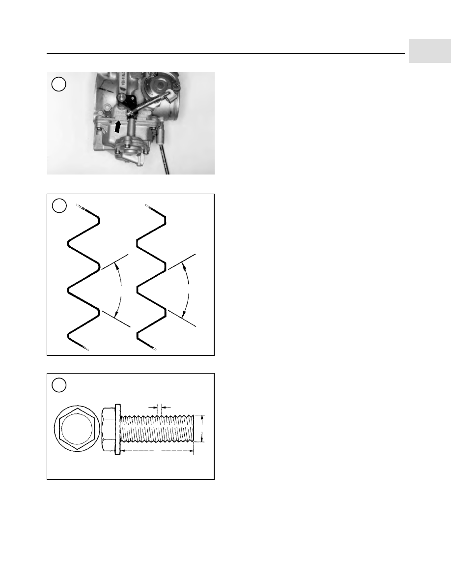
nut, manufacturers specify the internal diameter and the
thread pitch.

The measurement across two flats on a nut or bolt indi-

cates the wrench size.

WARNING

Do not install fasteners with a strength clas-
sification lower than what was originally in-
stalled by the manufacturer. Doing so may
cause equipment failure and/or damage.

Torque Specifications

The materials used in the manufacture of the motorcy-

cle may be subjected to uneven stresses if the fasteners of
the various subassemblies are not installed and tightened
correctly. Fasteners that are improperly installed or work
loose can cause extensive damage. It is essential to use an
accurate torque wrench, described in this chapter, with the
torque specifications in this manual.

Specifications for torque are provided in Newton-me-

ters (N•m), foot-pounds (ft.-lb.) and inch-pounds (in.-lb.).
Refer to

Table 7

for general torque specifications. To use

Table 7

, first determine the size of the fastener as de-

scribed in

Threaded Fasteners

in this section. Torque

specifications for specific components are at the end of
the appropriate chapters. Torque wrenches are covered in
the

Basic Tools

section.

Self-Locking Fasteners

Several types of bolts, screws and nuts incorporate a

system that creates interference between the two fasten-
ers. Interference is achieved in various ways. The most
common type is the nylon insert nut and a dry adhesive
coating on the threads of a bolt.

Self-locking fasteners offer greater holding strength

than standard fasteners, which improves their resistance
to vibration. Most self-locking fasteners cannot be reused.
The materials used to form the lock become distorted after
the initial installation and removal. It is a good practice to
discard and replace self-locking fasteners after their re-
moval. Do not replace self-locking fasteners with stan-
dard fasteners.

Washers

There are two basic types of washers: flat washers and

lockwashers. Flat washers are simple discs with a hole to
fit a screw or bolt. Lockwashers are used to prevent a fas-
tener from working loose. Washers can be used as spacers
and seals, or to help distribute fastener load and to prevent
the fastener from damaging the component.

As with fasteners, when replacing washers, make sure

the replacement washers are of the same design and qual-
ity.

GENERAL INFORMATION

5

1

7

8

U.S. Standard

Metric

60°

60°

Grade marking

T

-9.8

D

L

6

Cotter Pins

A cotter pin is a split metal pin inserted into a hole or

slot to prevent a fastener from loosening. In certain appli-
cations, such as the rear axle on an ATV or motorcycle, the
fastener must be secured in this way. For these applica-
tions, a cotter pin and castellated (slotted) nut is used.

To use a cotter pin, first make sure the diameter is cor-

rect for the hole in the fastener. After correctly tightening
the fastener and aligning the holes, insert the cotter pin
through the hole and bend the ends over the fastener (Fig-
ure 9
). Unless instructed to do so, never loosen a torqued
fastener to align the holes. If the holes do not align, tighten
the fastener just enough to achieve alignment.

Cotter pins are available in various diameters and

lengths. Measure length from the bottom of the head to the
tip of the shortest pin.

Snap Rings and E-clips

Snap rings (Figure 10) are circular-shaped metal re-

taining clips. They are required to secure parts and gears
in place on parts such as shafts, pins or rods. External type
snap rings are used to retain items on shafts. Internal type
snap rings secure parts within housing bores. In some ap-
plications, in addition to securing the component(s), snap
rings of varying thickness also determine endplay. These
are usually called selective snap rings.

Two basic types of snap rings are used: machined and

stamped snap rings. Machined snap rings (Figure 11) can
be installed in either direction, since both faces have sharp
edges. Stamped snap rings (Figure 12) are manufactured
with a sharp edge and a round edge. When installing a
stamped snap ring in a thrust application, install the sharp
edge facing away from the part producing the thrust.

Remove E-clips with a flat blade screwdriver by prying

between the shaft and E-clip. To install an E-clip, center it
over the shaft groove and push or tap it into place.

Observe the following when installing snap rings:

1. Remove and install snap rings with snap ring pliers.
See

Snap Ring Pliers

in this chapter.

2. In some applications, it may be necessary to replace
snap rings after removing them.

3. Compress or expand snap rings only enough to install
them. If overly expanded, they lose their retaining ability.

4. After installing a snap ring, make sure it seats com-
pletely.

5. Wear eye protection when removing and installing
snap rings.

SHOP SUPPLIES

Lubricants and Fluids

Periodic lubrication helps ensure a long service life for

any type of equipment. Using the correct type of lubricant
is as important as performing the lubrication service, al-
though in an emergency the wrong type is better than
none. The following section describes the types of lubri-
cants most often required. Make sure to follow the manu-
facturer’s recommendations for lubricant types.

6

CHAPTER ONE

9

10

Internal snap ring

Plain circlip

Correct installation
of cotter pin

External snap ring

E-clip

Engine oils

Engine oil is classified by two standards: the American

Petroleum Institute (API) service classification and the
Society of Automotive Engineers (SAE) viscosity rating.
This information is on the oil container label. Two letters
indicate the API service classification. The number or se-
quence of numbers and letter (10W-40 for example) is the
oil’s viscosity rating. The API service classification and
the SAE viscosity index are not indications of oil quality.

The service classification indicates that the oil meets

specific lubrication standards. The first letter in the classi-
fication (

S

) indicates that the oil is for gasoline engines.

The second letter indicates the standard the oil satisfies.

Always use an oil with a classification recommended

by the manufacturer. Using an oil with a different classifi-
cation can cause engine damage.

Viscosity is an indication of the oil’s thickness. Thin

oils have a lower number while thick oils have a higher
number. Engine oils fall into the 5- to 50-weight range for
single-grade oils.

Most manufacturers recommend multigrade oil. These

oils perform efficiently across a wide range of operating
conditions. Multigrade oils are identified by a (

W

) after

the first number, which indicates the low-temperature vis-
cosity.

Engine oils are most commonly mineral (petroleum)

based; however, synthetic and semi-synthetic types are
used more frequently. When selecting engine oil, follow
the manufacturer’s recommendation for type, classifica-
tion and viscosity.

Greases

Grease is lubricating oil with thickening agents added

to it. The National Lubricating Grease Institute (NLGI)
grades grease. Grades range from No. 000 to No. 6, with
No. 6 being the thickest. Typical multipurpose grease is
NLGI No. 2. For specific applications, manufacturers
may recommend water-resistant type grease or one with
an additive such as molybdenum disulfide (MoS

2

).

Brake fluid

Brake fluid is the hydraulic fluid used to transmit hy-

draulic pressure (force) to the wheel brakes. Brake fluid is
classified by the Department of Transportation (DOT).
Current designations for brake fluid are DOT 3, DOT 4
and DOT 5. This classification appears on the fluid con-
tainer.

Each type of brake fluid has its own definite character-

istics. The Harley-Davidson Softail uses the silicone
based DOT 5 brake fluid. Do not intermix DOT 3 or DOT
4 with DOT 5 type brake fluid as this may cause brake
system failure since the DOT 5 brake fluid is not compati-
ble with other brake fluids. When adding brake fluid,

only

use the fluid recommended by the manufacturer.

Brake fluid will damage any plastic, painted or plated

surface it contacts. Use extreme care when working with
brake fluid and clean up spills immediately with soap and
water.

Hydraulic brake systems require clean and moisture-

free brake fluid. Never reuse brake fluid. Keep containers
and reservoirs properly sealed.

WARNING

Never put a mineral-based (petroleum) oil
into the brake system. Mineral oil will cause
rubber parts in the system to swell and

GENERAL INFORMATION

7

1

11

12

Rounded edges

Sharp edges

Full support
areas

Directions
of thrust

Direction of thrust

break apart, resulting in complete brake
failure.

Cleaners, Degreasers and Solvents

Many chemicals are available to remove oil, grease and

other residue from the motorcycle. Before using cleaning
solvents, consider how they will be used and disposed of,
particularly if they are not water-soluble. Local ordi-
nances may require special procedures for the disposal of
many types of cleaning chemicals. Refer to

Safety

and

Parts Cleaning

in this chapter for more information on

their use.

To clean brake system components, use brake parts

cleaner. Petroleum-based products will damage brake sys-
tem seals. Brake parts cleaner leaves no residue. Use elec-
trical contact cleaner to clean electrical connections and
components without leaving any residue. Carburetor
cleaner is a powerful solvent used to remove fuel deposits
and varnish from fuel system components. Use this
cleaner carefully, as it may damage finishes.

Generally, degreasers are strong cleaners used to re-

move heavy accumulations of grease from engine and
frame components.

Most solvents are designed to be used in a parts wash-

ing cabinet for individual component cleaning. For safety,
use only nonflammable or high flash point solvents.

Gasket Sealant

Sealants are used with a gasket or seal and are occasion-

ally used alone. Follow the manufacturer’s recommenda-
tion when using sealants. Use extreme care when
choosing a sealant different from the type originally rec-
ommended. Choose sealants based on their resistance to
heat and various fluids, and their sealing capabilities.

One of the most common sealants is RTV, or room tem-

perature vulcanizing sealant. This sealant cures at room
temperature over a specific time period. This allows the
repositioning of components without damaging gaskets.

Moisture in the air causes the RTV sealant to cure. Al-

ways install the tube cap as soon as possible after applying
RTV sealant. RTV sealant has a limited shelf life and will
not cure properly if the shelf life has expired. Keep partial
tubes sealed and discard them if they have surpassed the
expiration date.

Applying RTV sealant

Clean all old gasket residue from the mating surfaces.

Remove all gasket material from blind threaded holes; it

can cause inaccurate bolt torque. Spray the mating sur-
faces with aerosol parts cleaner and wipe with a lint-free
cloth. The area must be clean for the sealant to adhere.

Apply RTV sealant in a continuous bead 2-3 mm

(0.08-0.12 in.) thick. Circle all the fastener holes unless
otherwise specified. Do not allow any sealant to enter
these holes. Assemble and tighten the fasteners to the
specified torque within the time frame recommended by
the RTV sealant manufacturer.

Gasket Remover

Aerosol gasket remover can help remove stubborn gas-

kets. This product can speed up the removal process and
prevent damage to the mating surface that may be caused
by using a scraping tool. Most of these types of products
are very caustic. Follow the gasket remover manufac-
turer’s instructions for use.

Threadlocking Compound

A threadlocking compound is a fluid applied to the threads

of fasteners. After the fastener is tightened, the fluid dries
and becomes a solid filler between the threads. This makes it
difficult for the fastener to work loose from vibration, or heat
expansion and contraction. Some threadlocking compounds
also provide a seal against fluid leakage.

Before applying threadlocking compound, remove any

old compound from both thread areas and clean them with
aerosol parts cleaner. Use the compound sparingly. Ex-
cess fluid can run into adjoining parts.

Threadlocking compounds are available in different

strengths. Follow the particular manufacturer’s recommen-
dations regarding compound selection. A number of manu-
facturers offer a wide range of threadlocking compounds
for various strength, temperature and repair applications.

8

CHAPTER ONE

13

3. Install two

new

round gaskets (C, Figure 6) on the

crankcase cover studs.

4. Slide the primary cover (B, Figure 2) over the locating
dowels and seat it flush against the gasket.

NOTE

The gasket sealing surface is very thin and
the overall size of the gasket is very large.
The gasket may shift prior to the installation
of the cover bolts. Make sure the gasket is
positioned correctly during installation of
the cover bolts in Step 5.

5. Install the primary cover bolts and captive washers
into the locations noted during removal. Tighten the pri-
mary cover bolts to 108-120 in.-lb. (12-14 N•m). Make
sure the gasket seats flush around the cover.

6. Install the primary chain inspection cover and gasket
(A, Figure 2). Tighten the primary chain inspection cover
screws to 84-108 in.-lb. (9-12 N•m).

7. On FLST models, install the front portion of the shift
lever assembly as described in Chapter Six.

8. On models so equipped, install the left side floorboard
as described in Chapter Fourteen.

9. Refill the primary chaincase with the type and quantity
of oil specified under

Primary Chaincase Lubrication

in

Chapter Three.

10. Connect the negative battery cable as described in
Chapter Eight.

CLUTCH ASSEMBLY

This section describes removal, inspection and installa-

tion of the clutch plates. If the clutch requires additional
service, refer to the clutch shell procedures in this chapter.

Refer to Figure 7.

CLUTCH AND PRIMARY DRIVE

205

5

2

3

4

5

6

Removal

NOTE

On models so equipped, always disarm the
optional TSSM security system prior to dis-
connecting the battery or the siren will
sound.

1. Disconnect the negative battery cable as described in
Chapter Eight.

2. Remove the clutch mechanism inspection cover and
quad ring (C, Figure 2).

3. At the clutch mechanism, loosen the clutch adjusting
screw locknut (A, Figure 8) and turn the adjusting screw
(B)

counterclockwise

to allow slack against the dia-

phragm spring.

4. Remove the primary chaincase outer cover as de-
scribed in this chapter.

206

CHAPTER FIVE

7

CLUTCH ASSEMBLY

1. Snap ring
2. Clutch shell and sprocket
3. Bearing
4. Snap ring
5. Clutch hub
6. Clutch nut
7. Diaphragm spring seat
8. Diaphragm spring
9. Friction disc B

10. Clutch plates
11. Friction disc A
12. Pressure plate
13. Diaphragm spring
14. Diaphragm spring

retainer

15. Bolt
16. Release plate
17. Snap ring

18. Snap ring
19. Thrust washer
20. Radial bearing
21. Oil slinger
22. Pushrod (right side)
23. Pushrod (right side)
24. Pushrod (left side)
25. Locknut

5. Loosen the bolts securing the diaphragm spring re-
tainer (A, Figure 9) in a crisscross pattern. Remove the
bolts and the retainer and diaphragm spring (B, Figure 9).
6. Remove the pressure plate.
7. Remove the clutch plates and friction discs from the
clutch shell.
8. Remove the damper spring and damper spring seat
from the clutch shell. Keep all parts in order as shown in
Figure 10.

Inspection

When measuring the clutch components, compare the

actual measurements to the specifications in Table 1. Re-
place parts that are out of specification or show damage as
described in this section.
1. Clean all parts in solvent and thoroughly dry them with
compressed air.
2. Inspect the friction discs as follows:

NOTE

If any friction disc is damaged or out of
specification as described in the following
steps, replace

all

of the friction discs as a

set. Never replace only one or two discs.

a. Inspect the friction material (Figure 11) for exces-

sive or uneven wear, cracks and other damage.
Check the disc tangs for surface damage. The sides
of the disc tangs must be smooth where they contact
the clutch shell finger; otherwise, the discs cannot
engage and disengage correctly.

NOTE

If the disc tangs are damaged, inspect the
clutch shell fingers carefully as described
later in this section.

b. Measure the thickness of each friction disc with a

vernier caliper (Figure 12). Measure at several
places around the disc.

3. Inspect the clutch plates (Figure 13) as follows:

a. Inspect the clutch plates for cracks, damage or color

change. Overheated clutch plates will have a blue
discoloration.

b. Check the clutch plates for oil glaze buildup. Re-

move buildup by lightly sanding both sides of each
plate with 400 grit sandpaper placed on a surface
plate or piece of glass. Clean off all sandpaper resi-
due after cleaning the clutch plate(s).

c. Place each clutch plate on a flat surface and check

for warp with a feeler gauge (Figure 14).

CLUTCH AND PRIMARY DRIVE

207

5

8

9

10

11


Content      ..      1      2      3      ..