Harley Davidson 2008 Touring Models. Service Manual - page 44
 

  Главная      Harley Davidson     Harley Davidson 2008 Touring Models. Service Manual


Search            copyright infringement  


Content      ..     42      43      44      45     ..


Harley Davidson 2008 Touring Models. Service Manual - page 44


Final Instructions

1.

Insert tapered end of new 7 in. cable strap into round hole
in turn signal switch bracket and then feed back through
using adjacent hole. Reserve oblong hole for bracket
screw. See 

Figure 8-143

.

NOTE

Be sure that all splices are positioned above the turn signal
switch bracket.

2.

Place turn signal switch assembly into housing aligning
oblong hole in bracket with lower bracket weld nut
(threaded boss on Road King Standard models). Be sure
that bracket is fully seated. Tabs on each side of bracket
are captured in slots cast into switch housing.

3.

Start screw to secure bracket inside housing.

If routed incorrectly, wires can be pinched by casting or
handlebar resulting in switch failure. (00542b)

4.

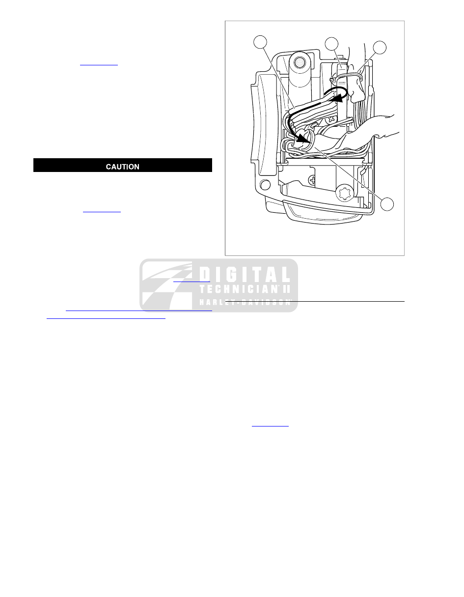
Loop switch wires, so that spliced lengths are positioned
as shown in 

Figure 8-144

.

5.

Capturing conduit about  0.25 in. (6.4 mm) from end,
securely tighten cable strap to draw conduit to bracket.
Remove any excess cable strap material.

6.

Tighten screw to secure bracket inside housing.

7.

Route wire bundle to upper switch housing below and then
forward of the main wire harness positioning conduit in
channel next to angular arm of bracket. See 

Figure 8-144

.

Secure bundle to arm using new cable strap. Cut any
excess cable strap material.

8.

See 

8.39 HANDLEBAR SWITCH ASSEMBLIES,

Assembly: Left Side Handlebar Switches

.

2

3

3

1

sm03701

1.

Splices

2.

Angular arm

3.

Cable strap

Figure 8-144. Lower Left Handlebar Switch Housing (With

Splices) - Classic/Ultra Models

GENERAL REPAIR PROCEDURES

1.

To better access wires and avoid damaging conduit with
radiant heating device, push conduit back and secure with
extra  7.0 in. (178 mm) cable strap in kit.

2.

Strip  0.5 in. (12.7 mm) of insulation off switch wires. Twist
stripped ends of switch wires until all strands are tightly
coiled.

3.

Cut dual wall heat-shrink tubing supplied in kit into  1.0
in. (25.4 mm) segments. Slide tubing over each wire of
new switch assembly.

NOTE

If absent from kit, obtain heat shrink tubing (Part No. 72266-
94) and two  7.0 in. (178 mm) cable straps (Part No. 10181).

4.

See 

Figure 8-145

. Matching wire colors, mate old and new

switch wires and splice as follows:

a.

Hold the wires so that the stripped ends cross (1).
Note that the wire on the left is on top and two-thirds
of its stripped length lies beyond the point where they
intersect. Looking at the other wire, only 1/3 of its
stripped length lies beyond the intersection point.

b.

Holding the wires together at their juncture, start the
splice by tightly twisting the top one-third length of
the right hand wire over the left (2).

c.

Tightly coil the remaining two-thirds of the left hand
wire around the right (3).

d.

Solder the spliced connections.

8-120  2008 Touring Service:  Electrical

NOTE

For best results, do one wire at a time.

5.

Center the heat-shrink tubing over the soldered splices.

Be sure to follow manufacturer's instructions when using
the UltraTorch UT-100 or any other radiant heating device.
Failure to follow manufacturer's instructions can cause a
fire, which could result in death or serious injury. (00335a)

Avoid directing heat toward any fuel system com-
ponent. Extreme heat can cause fuel ignition/explosion
resulting in death or serious injury.

Avoid directing heat toward any electrical system
component other than the connectors on which heat
shrink work is being performed.

Always keep hands away from tool tip area and heat
shrink attachment.

6.

See 

Figure 8-146

. Using the UltraTorch UT-100, Robinair

Heat Gun with heatshrink attachment or other suitable
radiant heating device, uniformly heat the heat-shrink
tubing to insulate and seal the soldered connections. Apply
heat just until the meltable sealant exudes out both ends
of the tubing and it assumes a smooth cylindrical appear-
ance.

NOTE

Electrically connected solder outside the tubing may cause a
short to ground resulting in switch failure.

7.

Inspect the melted sealant for solder beads. Excess solder
or heat may force some solder out with the melted sealant.
Use a small needle nose pliers to remove any solder
found. Briefly heat the connection to reseal the tubing if
solder beads were removed. Use less solder or reduce
heating time or intensity when doing subsequent splices.

8.

Cut cable strap compressing conduit and move to its ori-
ginal position.

1

2

3

sm03702

1.

Cross stripped ends

2.

Twist right wire

3.

Twist left wire

Figure 8-145. Splice Switch Wires

3

2

1

sm00082

1.

Ultra Torch UT-100

2.

Robinair Heat Gun

3.

Robinair Heat Gun Shrink Tool Attachment

Figure 8-146. Radiant Heating Devices

ASSEMBLY: RIGHT SIDE HANDLEBAR
SWITCHES

1.

If replacing lower housing switches, proceed to next step.
If replacing upper housing switches, proceed to step 8.

2008 Touring Service:  Electrical  8-121

2.

With concave side facing upward, install friction shoe so
that pin hole is over point of adjuster screw (non cruise
equipped models only).

NOTE

The friction shoe is a loose fit and may fall out or become dis-
lodged if lower switch housing is turned upside down or shaken.

3.

Position lower switch housing beneath throttle grip.

4.

Position upper switch housing over handlebar and lower
switch housing. Verify that wire harness conduit runs in
depression at bottom of handlebar.

5.

Start upper and lower switch housing screws, but do not
tighten.

6.

Position brake lever/master cylinder assembly inboard of
switch housing assembly engaging tab on lower switch
housing in groove at top of brake lever bracket.

7.

Align holes in handlebar clamp with those in master cyl-
inder housing and start lower screw (with flat washer).
Position for rider comfort. Beginning with top screw, tighten
screws to 72-80 in-lbs (8.0-9.0 Nm).

8.

Tighten lower and upper switch housing screws to 35-45
in-lbs (4.0-5.0 Nm).

NOTE

Always tighten lower switch housing screw first, so that any
gap between upper and lower housings is at front of switch
assembly.

9.

Remove cardboard insert between brake lever and lever
bracket.

10. Test switches for proper operation.

ASSEMBLY: LEFT SIDE HANDLEBAR
SWITCHES

1.

If replacing lower housing switches, proceed to next step.
If replacing upper housing switches, proceed to step 6.

2.

Install upper and lower switch housings on handlebar. Be
sure that ribs on outboard side of switch housings fit in
grooves molded into grip. Verify that wire harness conduit
runs in depression at bottom of handlebar.

3.

Start upper and lower switch housing screws, but do not
tighten.

4.

Position clutch hand lever assembly inboard of switch
housing assembly engaging tab on lower switch housing
in groove at bottom of clutch lever bracket.

5.

Align holes in handlebar clamp with those in clutch lever
bracket and start lower screw (with flat washer). Position
for rider comfort. Beginning with top screw, tighten screws
to 72-108 in-lbs (8.0-12.0 Nm).

6.

Tighten lower and upper switch housing screws to 35-45
in-lbs (4.0-5.0 Nm).

NOTE

Always tighten lower switch housing screw first, so that any
gap between upper and lower housings is at front of switch
assembly.

7.

Test switches for proper operation.

INSTALLATION

NOTE

While there are four different switch configurations for Touring
models (Road King, Road King Classic, Classic and Ultra), the
installation procedures are the same. To simplify these
instructions, only the Road King switch configuration is repres-
ented in the photographs and illustrations which follow.

Right Handlebar Controls

1.

With concave side facing upward, install friction shoe so
that pin hole is over point of adjuster screw (non cruise
equipped models only).

NOTE

The friction shoe is a loose fit and may fall out or become dis-
lodged if lower switch housing is turned upside down or shaken.

2.

Position lower switch housing beneath the throttle grip.

3.

Position upper switch housing over handlebar and lower
switch housing.

4.

Verify that wire harness conduit runs in the depression at
bottom of handlebar. Be sure that upper switch housing
harness will not be pinched under handlebar when switch
housing screws are tightened.

5.

Start upper and lower switch housing screws, but do not
tighten.

6.

Position brake lever/master cylinder assembly inboard of
switch housing assembly engaging tab on lower switch
housing in groove at top of brake lever bracket. See

Figure 8-147

.

7.

Align holes in handlebar clamp with those in master cyl-
inder housing and start two screws (with flat washers).
Position for rider comfort. Beginning with top screw, tighten
screws to 72-80 in-lbs (8.0-9.0 Nm).

8.

Tighten lower and upper switch housing screws to 35-45
in-lbs (4.0-5.0 Nm).

NOTE

Always tighten lower switch housing screw first, so that any
gap between upper and lower housings is at front of switch.

9.

Remove cardboard insert between brake lever and lever
bracket.

10. Secure wire harness conduit to handlebar using two new

cable straps. Position first cable strap approximately  4.0-
5.0 in. (102-127 mm) from handlebar clamp. Cut any
excess cable strap material.

11. Test switches for proper operation.

8-122  2008 Touring Service:  Electrical

1

4

5

3

2

sm05016

1.

Tab

2.

Groove

3.

Switch housing assembly

4.

Brake lever bracket

5.

Cardboard insert

Figure 8-147. Remove Master Cylinder/Brake Lever

Assembly

3

1

2

sm00083

1.

Grip sleeve

2.

Ribs

3.

Grooves

Figure 8-148. Install Left Handlebar Switch Housings

Left Handlebar Controls

1.

Install new hand grip, if removed. See 

2.24 HANDLE-

BARS, Left Hand Grip

.

2.

Install upper and lower switch housings on handlebar. Be
sure that ribs on outboard side of switch housings fit in
grooves molded into grip. See 

Figure 8-148

.

3.

Verify that wire harness conduit runs in groove at bottom
of handlebar. Be sure that upper switch housing harness
will not be pinched under handlebar when switch housing
screws are tightened.

4.

Start upper and lower switch housing screws, but do not
tighten.

5.

Position clutch hand lever assembly inboard of switch
housing assembly engaging tab on lower switch housing
in groove at bottom of clutch lever bracket. See

Figure 8-149

.

6.

Align holes in handlebar clamp with those in clutch lever
bracket and start two screws (with flat washers). Position
for rider comfort. Beginning with top screw, tighten screws
to 72-108 in-lbs (8.0-12.0 Nm).

7.

Tighten lower and upper switch housing screws to 35-45
in-lbs (4.0-5.0 Nm).

NOTE

Always tighten lower switch housing screw first, so that any
gap between upper and lower housings is at front of switch.

8.

Secure wire harness conduit to handlebar using two new
cable straps. Position first cable strap approximately  4.0-
5.0 in. (102-127 mm) from handlebar clamp. Cut any
excess cable strap material.

9.

Test switches for proper operation.

2

1

3

4

sm01255

1.

Clutch lever bracket

2.

Groove

3.

Tab

4.

Switch housing assembly

Figure 8-149. Fit Clutch Lever Bracket to Left Handlebar

Switch Housing

2008 Touring Service:  Electrical  8-123

1

2

4

3

sm02986

1.

Horn switch

2.

Headlamp dimmer switch HI/LO

3.

Left turn signal switch

4.

Clutch interlock switch

Figure 8-150. Road King Left Handlebar Controls

1

2

3

4

sm02988

1.

Electric starter switch

2.

Engine switch OFF/RUN

3.

Right turn signal switch

4.

Stoplight switch

Figure 8-151. Road King Right Handlebar Controls

1

3

2

4

5

sm02990

1.

Horn switch

2.

Headlamp dimmer switch

3.

Left turn signal switch

4.

Clutch interlock switch

5.

Cruise control switch ON/OFF

Figure 8-152. Road King Classic Left Handlebar Controls

1

2

5

3

4

sm02991

1.

Electric starter switch

2.

Engine switch OFF/RUN

3.

Right turn signal switch

4.

Stoplight switch

5.

Cruise control switch SET/RESUME

Figure 8-153. Road King Classic Right Handlebar Controls

8-124  2008 Touring Service:  Electrical

3

2

1

4

5

sm02992

1.

Horn switch

2.

Headlamp dimmer switch

3.

Left turn signal switch

4.

Clutch interlock switch

5.

Audio control switch

Figure 8-154. Classic Left Handlebar Controls

1

2

5

3

4

sm02993

1.

Electric starter switch

2.

Engine switch OFF/RUN

3.

Right turn signal switch

4.

Stoplight switch

Figure 8-155. Classic Right Handlebar Controls

3

6

2

1

4

5

sm02994

1.

Horn switch

2.

Headlamp dimmer switch

3.

Left turn signal switch

4.

Clutch interlock switch

5.

Squelch control and driver switch
PUSH/TRANSMIT

6.

Audio control switch

Figure 8-156. Ultra Left Handlebar Controls

1

2

5

3

4

6

sm02995

1.

Electric starter switch

2.

Engine switch OFF/RUN

3.

Right turn signal swtich

4.

Stoplight switch

5.

Mode select switch

6.

Cruise control switch SET/RESUME

Figure 8-157. Ultra Right Handlebar Controls

2008 Touring Service:  Electrical  8-125

SUBJECT

............................................................................................................................

PAGE NO.

A.1 AMP 1-PLACE CONNECTORS................................................................................................A-1
A.2 AMP MULTILOCK CONNECTORS..........................................................................................A-3
A.3 AUTOFUSE ELECTRICAL CONNECTORS.............................................................................A-7
A.4 DELPHI CONNECTORS..........................................................................................................A-8
A.5 DELPHI MAXI FUSE HOUSING.............................................................................................A-10
A.6 DEUTSCH ELECTRICAL CONNECTORS.............................................................................A-12
A.7 DEUTSCH STANDARD TERMINAL REPAIR.........................................................................A-16
A.8 DEUTSCH SOLID BARREL MINI TERMINAL REPAIR..........................................................A-17
A.9 DEUTSCH MINI TERMINAL REPAIR.....................................................................................A-19
A.10 MOLEX CONNECTORS.......................................................................................................A-20
A.11 PACKARD 150 METRI-PACK CONNECTORS.....................................................................A-24
A.12 PACKARD 280 METRI-PACK RELAY AND FUSE BLOCK CONNECTORS........................A-26
A.13 PACKARD 480 METRI-PACK CONNECTORS.....................................................................A-27
A.14 PACKARD 630 METRI-PACK CONNECTORS.....................................................................A-28
A.15 PACKARD METRI-PACK TERMINALS.................................................................................A-29
A.16 PACKARD ECM CONNECTOR............................................................................................A-31
A.17 PACKARD MICRO-64 CONNECTORS................................................................................A-33
A.18 SEALED SPLICE CONNECTORS.......................................................................................A-36

APPENDIX A CONNECT

OR REP

AIR

A.1

AMP 1-PLACE CONNECTORS

AMP 1-PLACE CONNECTOR REPAIR

TOOL NAME

PART NUMBER

PACKARD TERMINAL CRIMPER

HD-38125-7

SOCKET TERMINAL TOOL

HD-39621-27

PIN TERMINAL REMOVER

HD-39621-28

General

Obtain the necessary tools to repair the connector or terminals.

For terminal crimping, use the PACKARD TERMINAL
CRIMPER (Part No. HD-38125-7).

Separating Pin and Socket Housings

Bend back the ears on the pin housing slightly and separate
the pin and socket halves of the connector.

Mating Pin and Socket Housings

Push the pin and socket halves of the connector together until
the latches click.

Removing Socket Terminals

1.

See 

Figure A-1

. Grasp the lead on the wire end of the

socket housing (1) and push the terminal forward toward
the mating end of the connector until it stops. This will
disengage the locking tang from the groove in the con-
nector.

2.

Fit the barrel (2) of the SOCKET TERMINAL TOOL (Part
No. HD-39621-27) over the socket.

3.

While rotating the tool slightly, push until it bottoms (3) in
the socket housing.

4.

Allow the plunger (4) to "back out" of the handle.

5.

Holding the socket housing while keeping the tool firmly
bottomed (5), depress the plunger (6). The terminal (7)
pops out the wire end of the connector.

NOTE

If the terminal is not released from the socket housing, then
the terminal was not pushed forward far enough before place-
ment of the tool or the tool was not bottomed in the connector
housing.

Installing Socket Terminal

1.

Note the lip at the middle of the socket housing. One side
of the lip is flat while the other side is tapered. Insert the
wire terminal into the socket housing on the flat (lip) side.

2.

Push the lead into the socket housing until it stops. A click
is heard when the terminal is properly seated.

3.

Gently tug on the lead to verify that the terminal is locked
in place.

1

8

2

3

7

6

4

5

sm00011

1.

Socket housing

2.

Barrel

3.

Barrel bottomed in connector

4.

Plunger "backed out"

5.

Hold barrel bottomed

6.

Plunger pressed

7.

Socket terminal

8.

Connector lip

Figure A-1. Socket Terminal Tool (HD-39621-27)

Removing Pin Terminal

1.

Grasp the lead on the wire end of the pin housing and
push the terminal forward toward the mating end of the
connector until it stops. This will disengage the locking
tang from the groove in the connector.

2008 Touring Service:  Appendix A Connector Repair  A-1

2.

See 

Figure A-2

.

a.

Fit the barrel of the PIN TERMINAL REMOVER (Part
No. HD-39621-28) over the pin, and while rotating
the tool slightly, push until it bottoms in the housing.
Allow the plunger to "back out" of the handle.

b.

Holding the pin housing while keeping the tool firmly
bottomed, depress the plunger. The terminal pops
out the wire end of the connector.

NOTE

If the terminal is not released from the pin housing, then the
terminal was not pushed forward far enough before placement
of the tool or the tool was not bottomed in the connector
housing.

Installing Pin Terminal

1.

Push the lead into the pin housing until it stops. A click is
heard when the terminal is properly seated.

2.

Gently tug on the lead to verify that the terminal is locked
in place.

1

3

4

5

6

2

sm00012

1.

Pin housing

2.

Barrel

3.

Barrel bottomed in connector

4.

Plunger backed out of the handle

5.

Depressed plunger

6.

Pin terminal

Figure A-2. AMP Pin Terminal Remover (HD-39621-28)

A-2  2008 Touring Service:  Appendix A Connector Repair

A.2

AMP MULTILOCK CONNECTORS

AMP MULTILOCK CONNECTOR REPAIR

TOOL NAME

PART NUMBER

AMP MULTILOCK CRIMPER

HD-41609

General

AMP Multilock connectors are found between wire harnesses
and component wiring and may be either floating or anchored
to the frame with attachment clips.

See 

Figure A-3

. Attachment clips (1) on the pin housings are

fitted to T-studs on the motorcycle frame. The T-studs identify
OE connector locations. To maintain serviceability, always
return connectors to OE locations after service.

Obtain the necessary tools to repair the connector and ter-
minals.

NOTE

For terminal crimping use the AMP MULTILOCK
CRIMPER (Part No. HD-41609).

Separating Pin and Socket Housings

1.

If necessary, slide connector attachment clip T-stud to the
large end of the opening.

2.

See 

Figure A-3

. Depress the release button (2) on the

socket terminal side of the connector and pull the socket
housing (3) out of the pin housing (4).

Mating Pin and Socket Housings

1.

Hold the housings to match wire color to wire color.

2.

Insert the socket housing into the pin housing until it snaps
in place.

3.

If OE location is a T-stud, fit large opening end of attach-
ment clip over T-stud and slide connector to engage T-
stud to small end of opening.

2

3

1

4

sm00002

1.

Attachment clip

2.

Release button

3.

Socket housing

4.

Pin housing

Figure A-3. AMP Multilock Connector

Removing Terminals from Housing

1.

See 

Figure A-4

. Bend back the latch (1) to free one end

of secondary lock (2) then repeat on the opposite end.
Hinge the secondary lock outward.

2.

Look in the terminal side of the connector (opposite the
secondary lock) and note the cavity next to each terminal.

3.

Insert a pick or pin into the terminal cavity until it stops.

NOTE

If socket/pin terminal tool is not available, a push pin/safety pin
or a Snap-on pick (Part No. TT600-3) may be used.

4.

Press the tang in the housing to release the terminal.

a.

Socket: Lift the socket tang (8) up.

b.

Pin: Press the pin tang (7) down.

NOTE

A "click" is heard if the tang is released.

5.

Gently tug on wire to pull wire and terminal from cavity.

2008 Touring Service:  Appendix A Connector Repair  A-3

5

2

7

1

3

6

1

2

4

8

sm00013

1.

Latch

2.

Secondary lock open

3.

Pin housing

4.

Socket housing

5.

Pin terminal

6.

Socket terminal

7.

Tang (pin)

8.

Tang (socket)

Figure A-4. AMP Multilock Connector: Socket and Pin

Housings

Inserting Terminals into Housing

NOTE

See 

Figure A-5

. Cavity numbers are stamped into the sec-

ondary locks of both the socket and pin housings. Match the
wire color to the cavity number found on the wiring diagram.

1.

Hold the terminal so the catch faces the tang in the
chamber. Insert the terminal into its numbered cavity until
it snaps in place.

NOTES

Up and down can be determined by the position of the
release button, the button is the top of the connector.

On the pin side of the connector, tangs are positioned at
the bottom of each cavity, so the slot in the pin terminal
(on the side opposite the crimp tails) must face downward.

On the socket side, tangs are at the top of each cavity, so
the socket terminal slot (on the same side as the crimp
tails) must face upward.

2.

Gently tug on wire end to verify that the terminal is locked
in place.

3.

Rotate the hinged secondary lock inward until tabs fully
engage latches on both sides of connector.

– AMP

1

2

3

– AMP

1

2

3

4

5

6

5

6

7

8

9

10

4

3

2

1

1

2

3

sm00005

1.

3-place housing

2.

6-place housing

3.

10-place housing

Figure A-5. AMP Multilock Connector: Cavity Numbers on

Secondary Locks (Socket Housings Shown)

Preparing Wire Leads for Crimping

1.

Strip  5/32 in. (4.0 mm) of insulation from the wire lead.

A-4  2008 Touring Service:  Appendix A Connector Repair

2.

See 

Figure A-6

 and 

Figure A-7

. Select the pin/socket ter-

minals from the parts catalog and identify the insulation
crimp tails (1) and the wire crimp tails (2) and the groove
for the crimp tool locking bar (3).

3.

Identify the wire lead gauge and the corresponding crimper
tool and nesting die. Refer to 

Table A-1

.

Table A-1. AMP Multilock Connector: Crimp Tool Wire

Gauge/Nest

NEST

WIRE GAUGE

Front

20

Middle

16

Rear

18

2

3

1

sm00004

1.

Insulation crimp tail

2.

Wire crimp tail

3.

Locking bar groove

Figure A-6. AMP Multilock Connector: Pin Terminal

2

3

1

sm00001

1.

Insulation crimp tail

2.

Wire crimp tail

3.

Locking bar groove

Figure A-7. AMP Multilock Connector: Socket Terminal

Crimping Terminals to Leads

NOTE

Crimping with an Amp Multilock tool is a one step operation.
One squeeze crimps both the wire core and the insulation tails.

1.

See 

Figure A-8

. Squeeze the handles to cycle the AMP

MULTILOCK CRIMPER (Part No. HD-41609) to the fully
open position (1).

2.

Raise locking bar by pushing up on bottom flange (2).

NOTE

See 

Figure A-6

 and 

Figure A-7

. Hold the terminal with the

insulation crimp tail (1) facing up. The tool will hold the terminal
by the locking bar groove (3) and crimp the wire crimp tail (2)
around the bare wire of the stripped lead and the insulation
crimp tail around the insulation.

3.

See 

Figure A-8

With the insulation crimp tail facing

upward, insert terminal (pin or socket) (3) through the
locking bar, so that the closed side of the terminal rests
on the nest of the crimp tool.

4.

Release locking bar to lock position of contact (4). When
correctly positioned, the locking bar fits snugly in the space
at the front of the core crimp tails.

5.

Insert stripped end of lead (5) until ends make contact with
locking bar.

6.

Verify that wire is positioned so that wire crimp tails
squeeze bare wire strands, while insulation crimp tails fold
over the wire lead insulation.

7.

Squeeze handle of crimp tool until tightly closed. Tool
automatically opens when the crimping sequence is com-
plete.

8.

Raise up locking bar (8) and remove crimped terminal.

2008 Touring Service:  Appendix A Connector Repair  A-5

4

6

7

3

1

2

5

8

sm00007

1.

Open position

2.

Locking bar flange

3.

Insert contact

4.

Release locking bar

5.

Insert lead

6.

Squeeze

7.

Raise locking bar

8.

Remove crimped terminal

Figure A-8. AMP Multilock Connector: Terminal Crimping

Procedure

Inspecting Crimped Terminals

See 

Figure A-9

. Inspect the wire core crimp (2) and insulation

crimp (1). Distortion should be minimal.

1

2

sm00008

1.

Insulation crimp

2.

Wire core crimp

Figure A-9. AMP Multilock Connector: Terminal Crimp

A-6  2008 Touring Service:  Appendix A Connector Repair

A.3

AUTOFUSE ELECTRICAL CONNECTORS

AUTOFUSE CONNECTOR REPAIR

TOOL NAME

PART NUMBER

SNAP-ON TERMINAL PICK

GA500A

General

Autofuse electrical connector terminals are found in ignition
switches and some fuse blocks.

Disassembly

1.

Obtain SNAP-ON TERMINAL PICK (Part No. GA500A).

2.

See 

Figure A-10

 or 

Figure A-11

. Insert smallest pair of

pins into chamber on mating end of socket housing to
depress tangs on each side of terminal simultaneously.

3.

Gently pull on wire to remove terminal from wire end of
socket housing.

4.

If necessary, crimp new terminals on wires.

Assembly

1.

Using a thin flat blade, like that on a hobby knife, carefully
bend tang on each side of terminal outward away from
terminal body.

2.

With the open side of the terminal facing rib on wire end
of socket housing, insert terminal into chamber until it locks
in place.

sm02849

Figure A-10. Removing Autofuse Terminal from Ignition

Switch

sm03480

Figure A-11. Removing Autofuse Terminal from Fuse Block

2008 Touring Service:  Appendix A Connector Repair  A-7

A.4

DELPHI CONNECTORS

DELPHI CONNECTOR REPAIR

General

Delphi connectors are embossed with the brand name, Delphi,
on the housing latch.

Separating Pin and Socket Housings

See 

Figure A-12

. Bend back the external latch(es) slightly and

separate pin and socket halves of connector.

Mating Pin and Socket Housings

Push pin and socket halves of connector together until external
latch(es) engage.

Removing Socket Terminals

NOTE

Although the parts of the different Delphi connectors vary in
appearance, the instructions which follow will work for all. The
only exception is the oil pressure sender connector [139B], the
terminals of which are removed like the Packard push-to-seat
connectors. Therefore, see 

A.11 PACKARD 150 METRI-PACK

CONNECTORS

 to remove/install terminals in this connector.

1.

See 

Figure A-13

. If present, free one side of wire lock (1)

from ear on wire end of socket housing, then release the
other side. Release wires from channels in wire lock and
remove from socket housing.

2.

Use a fingernail to pry colored terminal lock (2) loose and
then remove from mating end of socket housing.

3.

Using a thin flat blade, like the unsharpened edge of a
hobby knife, gently pry tang (3) outward away from ter-
minal, and then tug on wire to back terminal out wire end
of chamber. Do not pull on wire until tang is released or
terminal will be difficult to remove.

Installing Socket Terminals

NOTE

For wire location purposes, alpha or numeric characters are
stamped into the wire end of each socket housing.

1.

Gently push tang on socket housing inward toward
chamber. With the open side of the terminal facing the
tang, push terminal into chamber at wire end of socket
housing.

2.

Gently tug on wire to verify that terminal is locked and will
not back out of chamber. If necessary, use fingernail to
push tang into engagement with terminal.

3.

Install colored terminal lock onto mating end of socket
housing.

4.

If present, seat wires in separate channels of wire lock
and then push channels inside chambers at wire end of
socket housing. Fully installed, slot on each side of wire
lock engages ear on socket housing.

sm00014

Figure A-12. Delphi Connector: Socket Housing Latch

A-8  2008 Touring Service:  Appendix A Connector Repair

2

3

1

sm00015

1.

Remove wire lock

2.

Remove terminal lock

3.

Pry tang outward

Figure A-13. Delphi Connector: Removing Socket

Terminals

2008 Touring Service:  Appendix A Connector Repair  A-9


Content      ..     42      43      44      45     ..