Harley Davidson 2008 Touring Models. Service Manual - page 43
 

  Главная      Harley Davidson     Harley Davidson 2008 Touring Models. Service Manual


Search            copyright infringement  


Content      ..     41      42      43      44     ..


Harley Davidson 2008 Touring Models. Service Manual - page 43


8.36

RADIO ANTENNA CABLE

FLHTC/U

Removal

1.

Remove fuel tank. See 

4.4 FUEL TANK

.

2.

Remove left side saddlebag. See 

2.27 SADDLEBAGS

.

3.

Remove left side cover.

4.

Remove outer fairing. See 

2.35 UPPER FAIRING AND

WINDSHIELD: FLHX, FLHT/C/U

.

5.

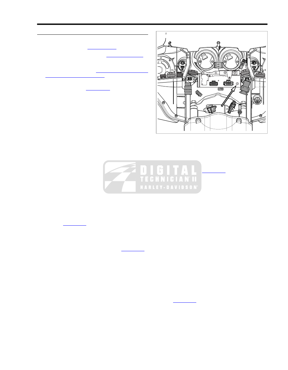
Remove radio antenna cable connector [51] at back of
radio (left side). See 

Figure 8-117

. Carefully cut cable

where it exits main harness conduit.

6.

Remove screw and P-clamp to release main harness
conduit from right side of steering head.

7.

Starting at front of wire trough, and working rearward, use
a small flat blade screwdriver to release catches on cover.
For best results, free one side of the cover and then the
other.

8.

Carefully cut two cable straps securing main harness
conduit to left upper frame tube. Cut cable strap securing
main harness conduit to luggage rack rail.

9.

Open Tour-Pak and proceed as follows:

a.

FLHTC: Remove rubber mat.

b.

FLHTCU: Open map pocket and remove acorn nuts
(with flat washers). Remove map pocket and molded
liner from Tour-Pak.

10. On FLHTCU models, depress external latch and remove

bulb socket from left side wrap-around light.

11. Rotate knurled ring to disconnect radio antenna cable

connector [29]. Release cable from two adhesive clips at
bottom of Tour-Pak.

12. Disconnect Tour-Pak lights connector [12], 3-place Multi-

lock. See 

Figure 8-118

.

13. Pull grommet into Tour-Pak and remove from main har-

ness conduit.

14. Pull Tour-Pak lights and radio antenna cable connectors

out through hole at front of Tour-Pak. See 

Figure 8-119

.

15. Carefully cut radio antenna cable where it exits main har-

ness conduit.

sm02954

Figure 8-117. Radio Antenna Cable Connector (FLHX,

FLHTC/U)

Installation

1.

Connect radio antenna cable connector [51] at back of
radio (left side). See 

Figure 8-117

.

2.

Route free end of radio antenna cable rearward along right
side of steering head.

3.

Capture radio antenna cable and main harness conduit in
P-clamp. Install screw to fasten P-clamp to right side of
steering head.

4.

Route radio antenna cable rearward through opening at
front right side of wire trough. Exiting wire trough at rear
left side, route cable along inboard side of left upper frame
tube. Continue rearward progression following luggage
rack rail to front of Tour-Pak.

5.

Loosely install two new cable straps to secure radio
antenna cable and main harness conduit to left upper
frame tube. On FLHTCU models, also capture audio har-
ness conduit at this location.

6.

Loosely install new cable strap to secure radio antenna
cable and main harness conduit to luggage rack rail.

7.

Feed Tour-Pak lights and radio antenna cable connectors
through hole at front of Tour-Pak. Capture cable and
conduit in grommet. Install grommet in hole with the larger
OD facing inside.

8.

Connect Tour-Pak lights connector [12], 3-place Multilock.
See 

Figure 8-118

.

9.

Rotate knurled ring to connect radio antenna cable con-
nector [29]. Capture cable in two adhesive clips at bottom
of Tour-Pak.

10. On FLHTCU models, install bulb socket of left side wrap-

around light.

2008 Touring Service:  Electrical  8-103

11. Tighten three cable straps securing radio antenna cable

and main harness conduit to left upper frame tube and
luggage rack rail. Cut any excess cable strap material.

12. Proceed as follows:

a.

FLHTC: Install rubber mat in Tour-Pak. Close Tour-
Pak.

b.

FLHTCU: Install molded liner in Tour-Pak. Install map
pocket and secure using acorn nuts (with flat
washers). Close Tour-Pak.

13. Place cover over wire trough. Starting at the rear and

working forward from side to side, engage catches to latch
cover. Verify that all latches are fully engaged.

14. Install fuel tank. See 

4.4 FUEL TANK

.

15. Install left side cover.

16. Install left side saddlebag. See 

2.27 SADDLEBAGS

.

17. Install outer fairing. See 

2.35 UPPER FAIRING AND

WINDSHIELD: FLHX, FLHT/C/U

.

1

4

3

2

sm02956

1.

Radio antenna cable

2.

Adhesive clip

3.

Tour-pak lights connector [12]

4.

Grommet

Figure 8-118. Disconnect Tour-Pak Lights Connector

2

3

1

sm02957

1.

Radio antenna cable connector [29]

2.

Grommet

3.

Tour-pak hole

Figure 8-119. Feed Main Harness Through Tour-Pak Hole

FLHX, FLTR

Removal

1.

Remove fuel tank. See 

4.4 FUEL TANK

.

2.

Remove left side saddlebag. See 

2.27 SADDLEBAGS

.

3.

Remove left side cover.

4.

Remove outer fairing. See 

2.35 UPPER FAIRING AND

WINDSHIELD: FLHX, FLHT/C/U

 or 

2.39 UPPER FAIRING

AND WINDSHIELD: FLTR

.

5.

Remove radio antenna cable connector [51] at back of
radio (left side). See 

Figure 8-120

. Carefully cut cable

where it exits main harness conduit.

6.

Remove screw and P-clamp to release main harness
conduit from right side of steering head, if present.

7.

Starting at front of wire trough, and working rearward, use
a small flat blade screwdriver to release catches on cover.
For best results, free one side of the cover and then the
other.

8.

Carefully cut two cable straps securing main harness
conduit to left upper frame tube.

9.

On left side of motorcycle, remove screw (with flat washer)
to remove passenger seat strap and saddlebag front
mounting bracket from chrome frame tube cover.

10. Remove screw and chrome frame tube cover.

11. Carefully cut cable strap to release radio antenna cable

from shoulder of upper frame tube (just in front of air valve
mounting bracket). Cut cable strap to release radio
antenna cable from slotted hole in rear fender support.
See 

Figure 8-121

.

12. At bottom of radio antenna bracket, rotate knurled ring to

disconnect radio antenna cable connector [29].

13. Carefully cut radio antenna cable where it exits main har-

ness conduit.

8-104  2008 Touring Service:  Electrical

sm02959

Figure 8-120. Radio Antenna Cable Connector (FLTR)

Installation

1.

Connect radio antenna cable connector [51] at back of
radio (left side). See 

Figure 8-120

.

2.

Proceed as follows:

a.

FLHX: Route free end of radio antenna cable rear-
ward along right side of steering head.

b.

FLTR: Route free end of radio antenna cable into
tunnel of fairing bracket pulling it out through opening
on right side of bracket and then continuing rearward
along right side of steering head.

3.

Capture radio antenna cable and main harness conduit in
P-clamp, if present. Install screw to fasten P-clamp to right
side of steering head.

4.

Route radio antenna cable rearward through opening at
front right side of wire trough. Exiting wire trough at rear
left side, route cable along inboard side of left upper frame
tube to area of rear fender support.

5.

Loosely install two new cable straps to secure radio
antenna cable and main harness conduit to left upper
frame tube.

6.

Install new cable strap to secure radio antenna cable (and
rear facia lamp wires on FLHX) to shoulder of left upper
frame tube (just in front of rear shock air valve mounting
bracket). Using slotted hole, install new cable strap to
secure radio antenna cable (and rear facia lamp wires on
FLHX) to rear fender support. See 

Figure 8-121

 or

Figure 8-122

.

7.

At bottom of radio antenna bracket, rotate knurled ring to
connect radio antenna cable connector [29].

8.

Tighten four cable straps securing radio antenna cable to
left upper frame tube and rear fender support. Cut any
excess cable strap material.

9.

Install chrome frame tube cover on frame tube. Install
screw and tighten to 25-40 in-lbs (2.8-4.5 Nm).

10. Insert screw (with flat washer) through passenger seat

strap and slotted hole of saddlebag front mounting bracket.
Insert screw into forward hole in chrome frame tube cover.
Snug screw, but do not tighten.

11. Place cover over wire trough. Starting at the rear and

working forward from side to side, engage catches to latch
cover. Verify that all latches are fully engaged.

12. Install fuel tank. See 

4.4 FUEL TANK

.

13. Install left side cover.

14. Install left side saddlebag. See 

2.27 SADDLEBAGS

.

15. Tighten saddlebag front mounting bracket screw to 60-96

in-lbs (6.8-10.8 Nm).

16. Install outer fairing. See 

2.35 UPPER FAIRING AND

WINDSHIELD: FLHX, FLHT/C/U

 or 

2.39 UPPER FAIRING

AND WINDSHIELD: FLTR

.

sm02960

Figure 8-121. Capture Radio Antenna Cable (FLTR)

2008 Touring Service:  Electrical  8-105

8.37

AUDIO HARNESS: FLHTCU

REMOVAL

1.

Remove fuel tank. See 

4.4 FUEL TANK

.

2.

Remove right side saddlebag. See 

2.27 SADDLEBAGS

.

3.

Remove right side cover.

4.

Repeat applicable steps to remove left side saddlebag
and side cover.

5.

Remove outer fairing. See 

2.35 UPPER FAIRING AND

WINDSHIELD: FLHX, FLHT/C/U

.

6.

See 

Figure 8-123

. Disconnect the following connectors:

a.

CB antenna cable [50], back of CB module (right
side).

b.

Audio to interconnect harness [6], 6-place Deutsch;
left side of radio.

c.

Radio [28], 35-place Amp; back of radio (left side).

d.

CB module [184], 12-place Deutsch; left side of radio.

7.

Remove screw and P-clamp to release audio and main
harness conduit from left side of steering head.

8.

Carefully pull audio harness rearward under left side of
fairing cap and allow conduit and connectors to hang over
top of engine guard.

9.

Open Tour-Pak. Open map pocket and remove acorn nuts
(with flat washers). Remove map pocket and molded liner
from Tour-Pak.

10. Disconnect CB antenna cable connector [104]. Release

cable from front adhesive clip at bottom of Tour-Pak. See

Figure 8-124

.

11. Pull grommet into Tour-Pak and remove from CB antenna

cable. Pull CB antenna cable out through hole at front of
Tour-Pak.

12. Remove trim ring and gently pull on conduit to draw rear

speaker/passenger controls connector [41], 6-place
Deutsch, out of right side speaker box. Disconnect con-
nector.

13. Carefully cut cable strap securing audio harness and CB

antenna cable to luggage rack rail.

14. Draw rear right section of audio harness forward allowing

conduit and connectors to hang beside the right side
passenger footboard.

15. Remove trim ring and gently pull on wire harness to draw

rear speaker/passenger controls connector [42], 6-place
Deutsch, out of left side speaker box. Disconnect con-
nector.

16. Release rear headset receptacle from bracket at bottom

of left side speaker box. Disengage spring loop in wire
jacket from tab on right side of license plate bracket.

17. Draw rear left section of audio harness forward allowing

conduit and connectors to hang beside the left side pas-
senger footboard.

18. Release console connector [53], 12-place Deutsch, from

attachment clip anchored in hole of frame weldment at
rear of battery tray. Disconnect connector.

19. Carefully cut four cable straps securing audio harness to

left and right upper frame tubes.

20. Starting at front of wire trough, and working rearward, use

a small flat blade screwdriver to release catches on cover.
For best results, free one side of the cover and then the
other.

21. Using a paint pen, draw a line where the audio harness

conduit enters the wire trough at the front and also where
it exits the left and right sides at the rear.

22. Draw a line on both sides of each cable strap capturing

the audio harness. A gentle tug on the harness will indicate
whether the cable strap must be cut. Carry the line over
onto the main harness where possible.

23. Carefully cut and remove all cables straps marked with

the paint pen.

24. Gently pull on audio harness to separate from the main

harness.

3

4

2

1

sm05185

1.

Audio to interconnect harness [6]

2.

Radio [28]

3.

CB antenna cable [50]

4.

CB module [184]

Figure 8-123. Audio Harness Connectors (FLHTCU)

2008 Touring Service:  Electrical  8-107

1

3

2

sm02963

1.

CB antenna cable connector [104]

2.

Adhesive clip

3.

Grommet

Figure 8-124. CB Antenna Cable Connector [104]

INSTALLATION

1.

Lay new and used audio harnesses side by side. Transfer
painted lines drawn on used harness to their approximate
locations on the new harness.

2.

Thread new cable straps through slots of wire trough
where removed. Properly installed, both ends of the cable
strap will be pointing upward.

NOTE

If additional clearance is needed for installation of the cable
straps, gently pry up rear of wire trough to release anchor pins
from holes in frame backbone. Reinstall wire trough after
placement of cable straps.

3.

Adjust main harness as necessary, so that the painted
lines are aligned with the cable straps installed in the wire
trough.

4.

Place audio harness on top of main harness aligning the
entrance and exit lines with the openings at front and rear
of wire trough. Verify that branch containing rear headset
receptacle runs down left side of wire trough, while branch
containing CB antenna cable connector runs down right
side.

5.

Start tail end of each cable strap into eyelet, but do not
tighten.

6.

Route front section of audio harness forward along left
side of steering head and then under left side of fairing
cap to front of inner fairing.

7.

Connect the following connectors:

a.

CB antenna cable [50], back of CB module (right
side).

b.

Audio to interconnect harness [6], 6-place Deutsch;
left side of radio.

c.

Radio [28], 35-place Amp; back of radio (left side).

d.

CB module [184], 12-place Deutsch; left side of radio.

8.

Install screw and P-clamp to fasten audio and main har-
ness conduit to left side of steering head.

9.

From where the audio harness exits rear right side of wire
trough, continue rearward progression along inboard side
of right upper frame tube (and chrome frame tube cover),
and then up the luggage rack rail to front of Tour-Pak.

10. Loosely install two new cable straps to secure audio har-

ness conduit to right upper frame tube.

11. Loosely install new cable strap to secure audio harness

conduit to luggage rack rail.

12. Feed CB antenna cable connector through hole at front

of Tour-Pak. Capture cable in grommet. Install grommet
in hole with the larger OD facing inside.

13. Connect CB antenna cable connector [104]. Capture cable

in front adhesive clip at bottom of Tour-Pak.

14. Tighten three cable straps securing audio harness conduit

to right upper frame tube and luggage rack rail. Cut any
excess cable strap material.

15. Connect rear speaker/passenger controls connector [41],

6-place Deutsch. Feed connector back up into right side
speaker box pressing trim ring into hole.

16. Connect console connector [53], 12-place Deutsch. Install

connector onto attachment clip anchored in hole of frame
weldment at rear of battery tray.

17. From where the audio harness exits rear left side of wire

trough, continue rearward progression along inboard side
of left upper frame tube (and chrome frame tube cover)
to the luggage rack rail.

18. Connect rear speaker/passenger controls connector [42],

6-place Deutsch. Feed connector back up into left side
speaker box pressing trim ring into hole.

19. Engage spring loop in wire jacket of rear headset recept-

acle onto tab on right side of license plate bracket. Capture
headset receptacle in bracket at bottom of left side speaker
box.

20. Install two new cable straps to secure audio harness

conduit to left upper frame tube. Cut any excess cable
strap material.

21. Install molded liner in Tour-Pak. Install map pocket and

secure using acorn nuts (with flat washers). Close Tour-
Pak.

22. Verify that audio harness runs through channel on front

left side of wire trough. Make final adjustments to harness,
so that painted lines are aligned with cable straps loosely
installed. Tighten cable straps and cut any excess cable
strap material.

23. Place cover over wire trough. Starting at the rear and

working forward from side to side, engage catches to latch
cover. Verify that all latches are fully engaged.

24. Install fuel tank. See 

4.4 FUEL TANK

.

25. Install side covers and saddlebags, right side first. See

2.27 SADDLEBAGS

.

26. Install outer fairing. See 

2.35 UPPER FAIRING AND

WINDSHIELD: FLHX, FLHT/C/U

.

8-108  2008 Touring Service:  Electrical

8.38

CB ANTENNA CABLE: FLHTCU

REMOVAL

1.

Remove fuel tank. See 

4.4 FUEL TANK

.

2.

Remove right side saddlebag. See 

2.27 SADDLEBAGS

.

3.

Remove right side cover.

4.

Remove outer fairing. See 

2.35 UPPER FAIRING AND

WINDSHIELD: FLHX, FLHT/C/U

.

5.

Rotate knurled ring to disconnect CB antenna cable con-
nector [50] at back of CB module (right side). See

Figure 8-125

. Carefully cut cable where it exits audio har-

ness conduit.

6.

Starting at front of wire trough, and working rearward, use
a small flat blade screwdriver to release catches on cover.
For best results, free one side of the cover and then the
other.

7.

Carefully cut two cable straps securing audio harness
conduit to right upper frame tube. Cut two cable straps
securing audio harness to luggage rack rail and
speaker/passenger controls conduit.

8.

Open Tour-Pak. Open map pocket and remove acorn nuts
(with flat washers). Remove map pocket and molded liner
from Tour-Pak.

9.

Disconnect CB antenna cable connector [104]. Release
cable from front adhesive clip at bottom of Tour-Pak. See

Figure 8-126

.

10. Pull grommet into Tour-Pak and remove from CB antenna

cable. Pull CB antenna cable out through hole at front of
Tour-Pak.

11. Carefully cut CB antenna cable where it exits audio har-

ness conduit.

sm02962

Figure 8-125. CB Antenna Cable Connector [50]

1

3

2

sm02963

1.

CB antenna cable connector [104]

2.

Adhesive clip

3.

Grommet

Figure 8-126. CB Antenna Cable Connector [104]

INSTALLATION

1.

Rotate knurled ring to connect CB antenna cable connector
[50] at back of CB module (right side).

2.

Route free end of CB antenna cable rearward along left
side of steering head.

3.

Remove screw and P-clamp to release audio and main
harness conduit from left side of steering head. Capture
CB antenna cable in P-clamp and reinstall.

4.

Route CB antenna cable through opening at front left side
of wire trough. Exiting wire trough at rear right side, route
cable along inboard side of right upper frame tube. Con-
tinue rearward progression following luggage rack rail to
front of Tour-Pak.

5.

Loosely install two new cable straps to secure CB antenna
cable and audio harness conduit to right upper frame tube.

6.

Loosely install new cable strap to secure CB antenna
cable and audio harness conduit to luggage rack rail.
Loosely install new cable strap to secure CB antenna
cable to speaker/passenger controls conduit. See

Figure 8-127

.

7.

Feed CB antenna cable connector through hole at front
of Tour-Pak. Capture cable in grommet. Install grommet
in hole with the larger OD facing inside.

8.

Connect CB antenna cable connector [104]. Capture cable
in front adhesive clip at bottom of Tour-Pak.

9.

Tighten three cable straps securing CB antenna cable and
audio harness conduit to right upper frame tube and lug-
gage rack rail. Tighten cable strap securing CB antenna
cable to speaker/passenger controls conduit. Cut any
excess cable strap material.

2008 Touring Service:  Electrical  8-109

10. Install molded liner in Tour-Pak. Install map pocket and

secure using acorn nuts (with flat washers). Close Tour-
Pak.

11. Place cover over wire trough. Starting at the rear and

working forward from side to side, engage catches to latch
cover. Verify that all latches are fully engaged.

12. Install fuel tank. See 

4.4 FUEL TANK

.

13. Install right side cover.

14. Install right side saddlebag. See 

2.27 SADDLEBAGS

.

15. Install outer fairing. See 

2.35 UPPER FAIRING AND

WINDSHIELD: FLHX, FLHT/C/U

.

sm05025

Figure 8-127. Capture Audio Harness and CB Antenna

Cable

8-110  2008 Touring Service:  Electrical

8.39

HANDLEBAR SWITCH ASSEMBLIES

REMOVAL

NOTE

While there are four different switch configurations for Touring
models (Road King, Road King Classic, Classic and Ultra), the
removal procedures are the same. To simplify these instruc-
tions, only the Road King switch configuration is represented
in the photographs and illustrations which follow.

Right Handlebar Controls

Do not remove or install the master cylinder assembly
without first positioning a 5/32-inch (4 mm) thick insert
between the brake lever and lever bracket. Removing or
installing the master cylinder assembly without the insert
in place may result in damage to the rubber boot and
plunger on the front stoplight switch. (00324a)

NOTE

Use the eyelet of a cable strap if the cardboard insert is not
available.

1.

Place cardboard insert between brake lever and lever
bracket. See 

Figure 8-128

.

2.

Remove two screws (with flat washers) securing handlebar
clamp to master cylinder housing. Remove brake
lever/master cylinder assembly and clamp from handlebar.

3.

Remove upper and lower switch housing screws.

4.

Remove friction shoe from end of tension adjuster screw
(non cruise equipped models only).

NOTE

The friction shoe is a loose fit and may fall out or become dis-
lodged if lower switch housing is turned upside down or shaken.

5.

Cut two cable straps to release wire harness conduit from
handlebar, if present.

1

4

5

3

2

sm05016

1.

Tab

2.

Groove

3.

Switch housing assembly

4.

Brake lever bracket

5.

Cardboard insert

Figure 8-128. Remove Master Cylinder/Brake Lever

Assembly

Left Handlebar Controls

1.

Remove two screws (with flat washers) securing handlebar
clamp to clutch lever bracket. Remove clutch hand lever
assembly and clamp from handlebar.

2.

Remove upper and lower switch housing screws.

3.

Cut two cable straps to release wire harness conduit from
handlebar, if present.

4.

Remove hand grip from handlebar, if damaged. See

2.24 HANDLEBARS, Left Hand Grip

.

DISASSEMBLY

Right Side Handlebar Switches

Do not remove or install the master cylinder assembly
without first positioning a 5/32-inch (4 mm) thick insert
between the brake lever and lever bracket. Removing or
installing the master cylinder assembly without the insert
in place may result in damage to the rubber boot and
plunger on the front stoplight switch. (00324a)

NOTE

Use the eyelet of a cable strap if the cardboard insert is not
available.

1.

Place cardboard insert between brake lever and lever
bracket.

2.

Remove upper and lower switch housing screws.

3.

If replacing lower housing switches, proceed to next step.
If replacing upper housing switches, proceed to

2008 Touring Service:  Electrical  8-111

8.39 HANDLEBAR SWITCH ASSEMBLIES, Specific
Repair Procedures: Upper Switch Housings

.

4.

Loosen upper screw securing handlebar clamp to master
cylinder housing. Remove lower clamp screw (with flat
washer).

5.

Remove friction shoe from end of tension adjuster screw
(non cruise equipped models only).

NOTE

The friction shoe is a loose fit and may fall out or become dis-
lodged if lower switch housing is turned upside down or shaken.

Left Side Handlebar Switches

1.

Remove upper and lower switch housing screws.

2.

If replacing lower housing switches, proceed to next step.
If replacing upper housing switches, proceed to

8.39 HANDLEBAR SWITCH ASSEMBLIES, Specific
Repair Procedures: Upper Switch Housings

.

3.

Loosen upper screw securing handlebar clamp to clutch
lever bracket. Remove lower clamp screw (with flat
washer).

SPECIFIC REPAIR PROCEDURES: UPPER
SWITCH HOUSINGS

NOTES

Regardless of model or option, all motorcycles use the
same upper switch housings.

Replace Engine Stop and Engine Start Switches as a
single assembly even if only one switch is determined to
be faulty.

Right Side Handlebar (All Models)

1.

From inside switch housing, remove screw to release
bracket. Remove bracket and switch assembly from
housing. See 

Figure 8-129

.

2.

Move cable conduit from beneath wing of bracket. Cut
wires  0.25 in. (6.4 mm) from old switches. Discard old
switch and bracket assembly.

3.

Slide conduit forward over severed ends of switch wires
and cut off  0.5 in. (12.7 mm) of conduit material. Push
conduit back to access switch wires.

4.

Separate new Engine Stop Switch and Start Switch wires
into two bundles.

NOTE

Replacement Stop Switch and Start Switch wires are cut to
length,  2.5 in. (63.5 mm) and  2.0 in. (50.8 mm), respectively,
and partially stripped.

5.

See 

8.39 HANDLEBAR SWITCH ASSEMBLIES, General

Repair Procedures

.

6.

Loop switch wires, so that spliced lengths are positioned
as shown in 

Figure 8-130

. Route wires downstream of

splices beneath wing on Engine Stop Switch side of
bracket as seen in 

Figure 8-129

.

7.

Install new 7.0 in. (178 mm) cable strap beneath wing on
Engine Start Switch side of bracket and capture wire
splices.

8.

Place switch assembly into upper housing aligning hole
in bracket with threaded hole in boss. Be sure that bracket
is fully seated. The step at edge of boss captures bottom
edge of bracket, while tabs on each side of bracket fit in
slots cast into housing.

9.

Install screw to secure bracket inside housing. Verify that
wing on Engine Stop Switch side of bracket captures edge
of conduit as shown in 

Figure 8-129

.

10. Securely tighten cable strap to draw splices to bracket.

Remove any excess cable strap material.

11. See 

8.39 HANDLEBAR SWITCH ASSEMBLIES,

Assembly: Right Side Handlebar Switches

.

NOTE

Replace Horn and High/Low Beam Switches as a single
assembly even if only one switch is determined to be faulty.

1

5

4

3

2

sm01368

1.

Start switch

2.

Stop switch

3.

Conduit

4.

Screw with lock washer

5.

Bracket

Figure 8-129. Upper Right Handlebar Switch Housing

(Without Splices)

8-112  2008 Touring Service:  Electrical

2

5

4

3

1

sm01369

1.

Start switch

2.

Stop switch

3.

Conduit

4.

Splices

5.

Cable strap

Figure 8-130. Upper Right Handlebar Switch Housing (With

Splices)

Left Side Handlebar (All Models)

1.

See 

Figure 8-131

. From inside switch housing, remove

screw to release bracket. Remove bracket and switch
assembly from housing.

2.

Move cable conduit from beneath wing of bracket. Cut
wires  0.25 in. (6.4 mm) from old switches. Discard old
switch and bracket assembly.

3.

Slide conduit forward over severed ends of switch wires
and cut off  0.5 in. (12.7 mm) of conduit material. Push
conduit back to access switch wires.

4.

Separate new Horn and High/Low Beam Switch wires into
two bundles.

NOTE

Replacement High/Low Beam Switch and Horn Switch wires
are cut to length,  2.5 in. (63.5 mm) and  2.0 in. (50.8 mm),
respectively, and partially stripped.

5.

See 

8.39 HANDLEBAR SWITCH ASSEMBLIES, General

Repair Procedures

.

6.

Loop switch wires, so that spliced lengths are positioned
as shown in 

Figure 8-132

. Route wires downstream of

splices beneath wing on High/Low Beam Switch side of
bracket as seen in 

Figure 8-131

.

7.

Install new 7.0 in. (178 mm) cable strap beneath wing on
Horn Switch side of bracket and capture wire splices.

8.

Place switch assembly into upper housing aligning hole
in bracket with threaded hole in boss. Be sure that bracket

is fully seated. The step at edge of boss captures bottom
edge of bracket, while tabs on each side of bracket fit in
slots cast into housing.

9.

Install screw to secure bracket inside housing. Verify that
wing on High/Low Beam Switch side of bracket captures
edge of conduit as shown in 

Figure 8-131

.

10. Securely tighten cable strap to draw splices to bracket.

Remove any excess cable strap material. See

Figure 8-132

.

11. See 

8.39 HANDLEBAR SWITCH ASSEMBLIES,

Assembly: Left Side Handlebar Switches

.

2

3

4

1

5

sm01371

1.

Horn switch

2.

High/low beam switch

3.

Conduit

4.

Screw with lock washer

5.

Bracket

Figure 8-131. Upper Left Handlebar Switch Housing

(Without Splices)

2008 Touring Service:  Electrical  8-113

1

5

2

4

3

sm00086

1.

Horn switch

2.

High/low beam switch

3.

Conduit

4.

Splices

5.

Cable strap

Figure 8-132. Upper Left Handlebar Switch Housing (With

Splices)

SPECIFIC REPAIR PROCEDURES: RIGHT
SIDE LOWER SWITCH HOUSINGS

Preliminary Instructions

1.

From inside switch housing, carefully cut cable strap to
free conduit from turn signal switch bracket, if present.

2.

Remove screw to release turn signal switch bracket.
Remove bracket and switch assembly from housing.

NOTE

On Classic and Ultra models, pull conduit back to introduce
some slack in wires or the tight fit of the bundle will prevent
removal of turn signal switch bracket.

Turn-Right Signal Switch (All Models)

1.

Cut wires  1.5 in. (38.1 mm) from old switch. Discard old
switch assembly.

NOTE

Replacement Turn-Right Signal Switch wires are cut to length,

1.5 in. (38.1 mm), and partially stripped.

2.

See 

8.39 HANDLEBAR SWITCH ASSEMBLIES, General

Repair Procedures

.

Front Stoplight Switch (All Models)

1.

Carefully remove wedge between switch and switch
housing, if present. To remove switch from housing,
depress plunger and slowly rotate switch upward while
rocking slightly.

2.

Cut wires  1.0 in. (25.4 mm) from old switch. Discard old
switch.

NOTE

Replacement Stoplight Switch wires are cut to length,  2.5
in. (63.5 mm), and partially stripped.

3.

See 

8.39 HANDLEBAR SWITCH ASSEMBLIES, General

Repair Procedures

.

4.

Carefully depress plunger against inside wall of switch
housing. With thumb over plunger bore, move switch into
installed position in switch housing cavity. When plunger
is positioned against thumb, slowly rotate switch downward
while rocking slightly. Release plunger only after switch
is properly positioned in cavity.

5.

Verify that plunger is square in bore and that boot is not
compressed, collapsed or torn. If necessary, gently work
plunger in and out until boot is fully extended.

6.

Push down on switch, so that it bottoms against housing
and wires run in groove at base of cavity. With concave
side facing outward, insert wedge between switch and
outboard side of switch housing. See 

Figure 8-133

.

7.

Push wedge down until it also bottoms against housing.
Verify that plunger is still square in bore and then place a
drop of RTV Silicone Sealant on upper corner of wedge.

Mode Select Switch (Classic and Ultra
Models)

1.

Pull keycap from switch shaft.

2.

Remove two lower bracket screws. Pull bracket and switch
from switch housing. See 

Figure 8-134

.

3.

Cut wires  1.25 in. (31.8 mm) from old switch. Discard
switch assembly.

NOTE

Replacement Mode Select Switch wires are cut to length,  2.25
in. (57.2 mm), and partially stripped.

4.

See 

8.39 HANDLEBAR SWITCH ASSEMBLIES, General

Repair Procedures

.

5.

Fit new switch into cavity, so that it sits on edge in a ver-
tical position (gray/white wire topside). Properly installed,
switch is captured by blocks cast into lower housing. Verify
that switch shaft is aligned for proper keycap operation.

6.

Place lower bracket into housing (with weld nut side down),
but keep splices above bracket. Verify that slots in upper
step of bracket engage two tabs on switch body.

7.

Install shorter screw to secure front side of lower bracket
to threaded boss. Install longer rear screw. To engage
threaded hole in casting, use thru hole in lower step of
bracket on Classic models, thru hole in upper step on
Ultra.

8.

Install keycap on switch shaft.

8-114  2008 Touring Service:  Electrical

4

1

2

3

sm00080

1.

Stoplight switch

2.

Wedge

3.

Switch wires

4.

Lower switch housing

Figure 8-133. Install Stoplight Switch

1

2

3

2

sm03693

1.

Turn signal switch bracket screw

2.

Lower bracket screw

3.

Cable strap

Figure 8-134. Lower Right Handlebar Switch Housing

(Without Splices) - Classic/Ultra Models

3

1

2

sm00081

1.

Cable strap

2.

Bracket

3.

Right turn signal switch

Figure 8-135. Insert Cable Strap in Switch Bracket

Cruise Set/Resume Switch (Road King
Classic and Ultra Models)

1.

Pull keycap from switch shaft.

2.

Remove two lower bracket screws. Pull bracket and switch
from switch housing.

3.

Cut wires  1.5 in. (38.1 mm) from old switch. Discard switch
assembly.

NOTE

Replacement Cruise Set/Resume Switch wires are cut to
length,  2.0 in. (50.8), and partially stripped.

4.

See 

8.39 HANDLEBAR SWITCH ASSEMBLIES, General

Repair Procedures

.

5.

Fit new switch into cavity, so that it sits in a horizontal
position (blue/black wire towards master cylinder). Properly
installed, switch is captured by blocks cast into lower
housing.

6.

Keeping splices above bracket, install lower bracket (weld
nut side down), so that lower step is positioned over
switch. Slots in upper step engage two tabs on plastic
insert (Road King Classic) or on body of Mode Select
Switch (Ultra models).

NOTE

The Mode Select Switch is vertically oriented with the
gray/white wire topside.

7.

Install shorter screw to secure front side of lower bracket
to threaded boss. Install longer rear screw. Use thru hole
in upper step of bracket to engage threaded hole in
casting.

2008 Touring Service:  Electrical  8-115

8.

Note lettering for proper orientation and gently push
keycap onto switch shaft.

Final Instructions

1.

Insert tapered end of new 7.0 in. (178 mm) cable strap
into round hole in turn signal switch bracket and then feed
back through using adjacent hole. Reserve oblong hole
for bracket screw. See 

Figure 8-135

.

NOTE

Be sure that all splices are positioned above the turn signal
switch bracket.

2.

Place turn signal switch assembly into housing aligning
oblong hole in bracket with lower bracket weld nut
(threaded boss on Road King Standard models). Be sure
that bracket is fully seated. Tabs on each side of bracket
are captured in slots cast into switch housing.

3.

Start screw to secure bracket inside housing.

If routed incorrectly, wires can be pinched by casting or
handlebar resulting in switch failure. (00542b)

4.

Loop switch wires, so that spliced lengths are positioned
as shown in 

Figure 8-136

 or 

Figure 8-137

.

5.

Capturing conduit about  0.25 in. (6.4 mm) from end,
securely tighten cable strap to draw conduit to bracket.
Remove any excess cable strap material.

6.

Install second  7.0 in. (178 mm) cable strap capturing
conduit and wire splices. Securely tighten cable strap to
draw splices to conduit. Remove any excess cable strap
material.

7.

Tighten screw to secure bracket inside housing.

8.

Route wire bundle to upper switch housing by gently
pressing conduit into channel next to angular arm of
bracket. Secure bundle to arm using third cable strap.

Cut any excess cable strap material. If necessary, bend
angular arm of bracket downward to firmly secure Front
Stoplight Switch in installed position.

9.

See 

8.39 HANDLEBAR SWITCH ASSEMBLIES,

Assembly: Right Side Handlebar Switches

.

1

2

3

4

5

sm03694

1.

Angular arm

2.

Cable strap (wire bundle to arm)

3.

Cable strap (conduit to bracket)

4.

Cable strap (splices to conduit)

5.

Splices

Figure 8-136. Mode Select Handlebar Switch Housing

(Lower Right) - Classic/Ultra Models

8-116  2008 Touring Service:  Electrical

1

2

3

4

5

sm03695

1.

Angular arm

2.

Cable strap (wire bundle to arm)

3.

Cable strap (conduit to bracket)

4.

Cable strap (splices to conduit)

5.

Splices

Figure 8-137. Cruise Control Handlebar Switch Housing

(Lower Right) - Classic/Ultra Models

SPECIFIC REPAIR PROCEDURES: LEFT
SIDE LOWER SWITCH HOUSINGS

Preliminary Instructions

1.

From inside switch housing, carefully cut cable strap to
free conduit from turn signal switch bracket, if present.

2.

Remove screw to release turn signal switch bracket.
Remove bracket and switch assembly from housing.

NOTE

On Classic and Ultra models, pull conduit back to introduce
some slack in wires or the tight fit of the bundle will prevent
removal of the switch bracket.

Turn-Left Signal Switch (All Models)

1.

Cut wires  1.5 in. (38.1 mm) from old switch. Discard old
switch assembly.

NOTE

Replacement Turn-Left Signal Switch wires are cut to length,

1.5 in. (38.1 mm), and partially stripped.

2.

See 

8.39 HANDLEBAR SWITCH ASSEMBLIES, General

Repair Procedures

.

Clutch Interlock Switch

1.

Cut wires  0.25 in. (6.4 mm) from old switch. Discard switch
assembly.

NOTE

Replacement Clutch Interlock Switch wires are cut to length
and partially stripped. Looking at backside, left side switch wire
is  2.25 in. (57.2 mm) long, right side is  2.75 in. (70 mm) long.

2.

See 

8.39 HANDLEBAR SWITCH ASSEMBLIES, General

Repair Procedures

.

3.

Seat switch in cavity. Verify that plunger is square in bore
and that boot is not compressed, collapsed or torn. Push
down on switch, so that it bottoms against housing and
wires run in groove at base of cavity.

1

2

3

5

4

sm03696

1.

Clutch interlock switch

2.

Left turn signal switch and bracket

3.

Lower bracket

4.

Audio control switch

5.

Audio switch keycap

Figure 8-138. Lower Left Handlebar Switch Assembly

(Classic)

2008 Touring Service:  Electrical  8-117

3

2

4

1

5

sm03697

1.

Lower bracket

2.

Right turn signal switch and bracket

3.

Stoplight switch

4.

Mode select switch

5.

Mode select keycap

Figure 8-139. Lower Right Handlebar Switch Assembly

(Classic)

1

2

3

7

5

4

6

sm03698

1.

Clutch interlock switch

2.

Left turn signal switch and bracket

3.

Lower bracket

4.

Audio control switch

5.

Audio switch keycap

6.

PTT switch

7.

PTT switch keycap

Figure 8-140. Lower Left Handlebar Switch Assembly

(Ultra)

3

2

1

7

6

5

4

sm03699

1.

Lower bracket

2.

Stoplight switch

3.

Right turn signal switch and bracket

4.

Cruise control switch

5.

Mode select switch

6.

Mode select keycap

7.

Cruise switch keycap

Figure 8-141. Lower Right Handlebar Switch Assembly

(Ultra)

1

2

4

3

sm03700

1.

Lower bracket screw

2.

Turn signal switch bracket screw

3.

Cable strap

4.

Lower bracket screw

Figure 8-142. Lower Left Handlebar Switch Housing

(Without Splices) - Classic/Ultra Models

8-118  2008 Touring Service:  Electrical

Audio Control Switch (Classic and Ultra
Models)

1.

Pull keycap from switch shaft.

2.

Remove two lower bracket screws. See 

Figure 8-142

. Pull

bracket and switch from switch housing.

3.

Cut wires  1.25 in. (31.8 mm) from old switch. Discard
switch assembly.

NOTE

Replacement Audio Control Switch wires are cut to length,

2.25 in. (57.2 mm), and partially stripped.

4.

See 

8.39 HANDLEBAR SWITCH ASSEMBLIES, General

Repair Procedures

.

5.

Fit new switch into cavity, so that it sits on edge in a ver-
tical position (gray/green wire topside). Properly installed,
switch is captured by blocks cast into lower housing. Verify
that switch shaft is aligned for proper keycap operation.

6.

Place lower bracket into housing (with weld nut side down),
but keep splices above bracket. Verify that slots in upper
step of bracket engage two tabs on switch body.

7.

Install shorter screw to secure front side of lower bracket
to threaded boss. Install longer rear screw. To engage
threaded hole in casting, use thru hole in lower step of
bracket on Classic models, thru hole in upper step on
Ultra.

8.

Note lettering for proper orientation and gently push
keycap onto switch shaft.

CB Push-To-Transmit Switch (Ultra Models)

1.

Pull keycap from switch shaft.

2.

Remove two lower bracket screws. See 

Figure 8-142

. Pull

bracket and switch from switch housing.

3.

Cut wires  1.5 in. (38.1 mm) from old switch. Discard switch
assembly.

NOTE

Replacement Push-to-Transmit Switch wires are cut to length,

2.0 in. (50.8), and partially stripped.

4.

See 

8.39 HANDLEBAR SWITCH ASSEMBLIES, General

Repair Procedures

.

5.

Fit new switch into cavity, so that it sits in a horizontal
position (brown/black wire towards clutch lever bracket).
Properly installed, switch is captured by blocks cast into
lower housing.

6.

Keeping splices above bracket, install lower bracket (weld
nut side down), so that lower step is positioned over Push-
to-Transmit Switch (horizontally oriented). Slots in upper
step engage two tabs on body of Audio Control Switch
(vertically oriented with gray wire topside).

7.

Install shorter screw to secure front side of lower bracket
to threaded boss. Install longer rear screw. To engage
threaded hole in casting, use thru hole in upper step of
bracket.

8.

Note lettering for proper orientation and gently push
keycap onto switch shaft.

Cruise On/Off Switch (Road King Classic
Models)

1.

Pull keycap from switch shaft.

2.

Remove two lower bracket screws. Pull bracket and switch
from switch housing.

3.

Cut wires  1.5 in. (38.1 mm) from old switch. Discard switch
assembly.

NOTE

Cut replacement Cruise On/Off Switch wires to  2.0 in. (50.8
mm) and strip  0.5 (12.7 mm) of insulation.

4.

See 

8.39 HANDLEBAR SWITCH ASSEMBLIES, General

Repair Procedures

.

5.

Fit new switch into cavity, so that it sits in a horizontal
position (orange/white wire towards clutch lever bracket).
Properly installed, switch is captured by blocks cast into
lower housing.

6.

Keeping splices above bracket, install lower bracket (weld
nut side down), so that lower step is positioned over
switch. Slots in upper step engage two tabs on plastic
insert.

7.

Install shorter screw to secure front side of lower bracket
to threaded boss. Install longer rear screw. Use thru hole
in upper step of bracket to engage threaded hole in
casting.

8.

Note lettering for proper orientation and gently push
keycap onto switch shaft.

3

1

2

sm00087

1.

Cable strap

2.

Bracket

3.

Left turn signal switch

Figure 8-143. Insert Cable Strap in Switch Bracket

2008 Touring Service:  Electrical  8-119


Content      ..     41      42      43      44     ..