Harley Davidson 2008 Touring Models. Service Manual - page 41
 

  Главная      Harley Davidson     Harley Davidson 2008 Touring Models. Service Manual


Search            copyright infringement  


Content      ..     39      40      41      42     ..


Harley Davidson 2008 Touring Models. Service Manual - page 41


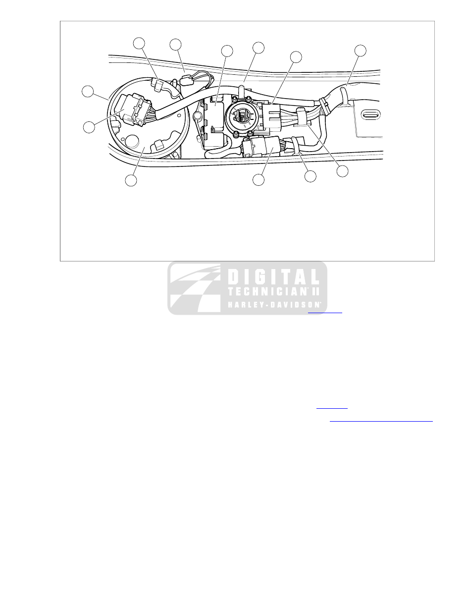
7

8

9

3

1

4

1

2

6

5

1

10

sm02977

6.

1.

Odometer reset switch

Metal clip (3)

2.

7.

Plastic clip

Latch (1 of 3)

8.

3.

Lock ring

Ignition/light key switch connector [33]

4.

9.

Indicator lights connector [21]

Speedometer connector [39]

10.

5.

Speedometer

Indicator lights assembly

Figure 8-89. Instument Console Assembly (FLHR/C)

Installation

1.

Lubricate groove in rubber gasket with isopropyl alcohol
or glass cleaner. Place the gasket into position around the
console speedometer bore.

2.

From top side of console, feed speedometer into rubber
gasket. Lubricate gasket with isopropyl alcohol or glass
cleaner, if necessary. The speedometer should fit snugly
against the gasket without movement.

3.

Turn console over. Place lock ring over back of speedo-
meter aligning two slots with console bosses. Press latches
down until they lock into position.

4.

Install speedometer connector [39], 12-place Packard.

5.

If released, bend flexible metal clips to capture connector
conduit . See 

Figure 8-89

.

6.

Exercising caution to avoid pinching wire harness and vent
tube, position console on fuel tank.

7.

Start socket screw to fasten front of console to fuel tank
weldment.

8.

Start hex screw to fasten rear console bracket to clip nut
on rear fuel tank bracket.

9.

Alternately tighten socket/hex screws to 36-60 in-lbs (4.1-
6.8 Nm).

10. Install seat. See 

2.26 SEAT

.

11. Install maxi-fuse. See 

8.5 SYSTEM FUSES AND RELAYS

.

2008 Touring Service:  Electrical  8-71

8.31

INDICATOR LAMPS: FLHR/C

INDICATOR LIGHTS

Removal

NOTE

All models are equipped with Light Emitting Diodes (LEDs) in
lieu of indicator lamps. The indicator light assembly is not ser-
viceable. If one LED is bad, the indicator light assembly must
be replaced.

1.

Remove maxi-fuse. See 

8.5 SYSTEM FUSES AND

RELAYS

.

2.

Remove seat. See 

2.26 SEAT

.

3.

Remove socket screw to release front of console from fuel
tank weldment.

4.

Remove hex screw to release rear console bracket from
clip nut on rear fuel tank bracket.

5.

Lay a clean shop towel on forward part of rear fender.
Remove console and lay upside down on shop towel.

6.

Disconnect indicator lights connector [21], 8-place Deutsch
(black). If necessary, bend flexible metal clip to free con-
nector conduit. See 

Figure 8-90

.

7.

Remove indicator lights assembly from console as follows:

a.

Insert the blade of a large screwdriver under rear
corner of indicator lights assembly.

b.

Using thumb and index finger, squeeze front and rear
paddles on same side of assembly while rotating
screwdriver.

c.

When one side of assembly becomes free, repeat
procedure on opposite side to release unit from con-
sole.

Installation

1.

Install indicator lights assembly into console as follows:

a.

Place assembly into position in console engaging four
paddles in slots of indicator light assembly.

b.

While pushing down on assembly with thumbs, push
up on lense on outboard side of console until
assembly fits snugly.

3

2

1

sm02978

1.

Metal clip

2.

Indicator lights connector [21]

3.

Paddles

Figure 8-90. Release Paddles to Free Indicator Lights

Assembly (FLHR/C)

2.

Connect indicator lights connector [21], 8-place Deutsch
(black). If released, bend flexible metal clip to capture
connector conduit.

3.

Exercising caution to avoid pinching wire harness and vent
tube, position console on fuel tank.

4.

Start socket screw to fasten front of console to fuel tank
weldment.

5.

Start hex screw to fasten rear console bracket to clip nut
on rear fuel tank bracket.

6.

Alternately tighten socket/hex screws to 36-60 in-lbs (4.1-
6.8 Nm).

7.

Install seat. See 

2.26 SEAT

.

8.

Install maxi-fuse. See 

8.5 SYSTEM FUSES AND RELAYS

.

8-72  2008 Touring Service:  Electrical

8.32

ADVANCED AUDIO SYSTEM

RADIO (STORAGE BOX)

Removal

1.

Remove maxi-fuse. See 

8.5 SYSTEM FUSES AND

RELAYS

.

2.

Remove outer fairing. See 

2.35 UPPER FAIRING AND

WINDSHIELD: FLHX, FLHT/C/U

 or 

2.39 UPPER FAIRING

AND WINDSHIELD: FLTR

.

3.

FLHX, FLHTC, FLTR:

a.

Disconnect radio connector [27], 23-place Amp.

b.

Disconnect radio antenna cable connector [51].

4.

FLHTCU:

a.

Disconnect radio connector [27], 23-place Amp.

b.

Disconnect radio antenna cable connector [51].

c.

Disconnect radio connector [28], 35-place Amp.

d.

Disconnect CB antenna cable connector [50].

e.

Disconnect CB module connector [184], 12-place
Deutsch (black).

f.

Remove screw to release flange of CB module from
radio. Remove CB module.

5.

Using a long shank ball end socket (Snap-on® FABL6E),
remove four screws to release radio (storage box on FLHT)
from left and right radio support brackets. Use oblong
holes in fairing brackets to access screws. See

Figure 8-92

.

6.

Pull radio (storage box on FLHT) forward to remove from
opening in inner fairing.

4

3

2

5

1

sm02964

1.

Radio [27]

2.

Radio antenna cable [51]

3.

Radio [28]

4.

CB antenna cable [50]

5.

CB module [184]

Figure 8-91. Radio/CB Connections (FLHTC/U)

sm02965

Figure 8-92. Release Radio from Fairing Brackets

(FLHTC/U)

Installation

1.

Position radio (storage box on FLHT) between radio sup-
port brackets and push into opening in inner fairing.

2008 Touring Service:  Electrical  8-73

2.

Align threaded inserts in sides of radio (storage box on
FLHT) with holes in left and right radio support brackets.
Starting at the rear, install four screws. Alternately tighten
screws to 35-45 in-lbs (4.0-5.1 Nm). Use oblong holes in
fairing brackets to access screws.

3.

FLHX, FLHTC, FLTR:

a.

Connect radio connector [27], 23-place Amp.

b.

Connect radio antenna cable connector [51].

4.

FLHTCU:

a.

Fit metal cones on CB module into rubber grommets
at top of radio. Use the position above radio connector
[28], 35-place Amp, as the other location has been
reserved for certain P&A accessories.

b.

Install screw to fasten flange of CB module to radio.
Tighten screw to 35-45 in-lbs (4.0-5.1 Nm).

c.

Connect radio connector [28], 35-place Amp.

d.

Connect CB antenna cable connector [50].

e.

Connect CB module connector [184], 12-place
Deutsch (black).

f.

Connect radio connector [27], 23-place Amp.

g.

Connect radio antenna cable connector [51].

5.

Install outer fairing. See 

2.35 UPPER FAIRING AND

WINDSHIELD: FLHX, FLHT/C/U

 or 

2.39 UPPER FAIRING

AND WINDSHIELD: FLTR

.

6.

Install maxi-fuse. See 

8.5 SYSTEM FUSES AND RELAYS

.

FRONT FAIRING SPEAKERS

Removal

1.

Remove outer fairing. See 

2.35 UPPER FAIRING AND

WINDSHIELD: FLHX, FLHT/C/U

 or 

2.39 UPPER FAIRING

AND WINDSHIELD: FLTR

.

2.

Carefully pull socket terminals from speaker spade con-
tacts.

3.

Remove three screws to release speaker adapter
assembly from inner fairing.

4.

Carefully pull speaker from adapter.

Installation

1.

With the speaker spade contacts at the top of the adapter,
the top being the side with the widest edge, snap speaker
into adapter using finger pressure.

2.

If speaker grille is loose, apply 3M-847 adhesive (HD Part
No. 99618-60) to outer edge of adapter ring. Install grille
on adhesive.

3.

With the widest edge of adapter at the top, align holes in
speaker adapter assembly with those in inner fairing.

4.

Start two long screws to secure top of speaker adapter
assembly to inner fairing. Capturing fairing support brace,
install short screw in lower outboard hole (positioning flat
washer between adapter and support brace). The screw
hole on the lower inboard side is not used.

5.

Tighten lower speaker screw to 22-28 in-lbs (2.5-3.2 Nm).
Tighten two upper speaker screws to 35-50 in-lbs (4.0-
5.7 Nm).

6.

Install socket terminals onto speaker spade contacts. Dif-
ferent size spade contacts prevent improper assembly.

7.

Install outer fairing. See 

2.35 UPPER FAIRING AND

WINDSHIELD: FLHX, FLHT/C/U

 or 

2.39 UPPER FAIRING

AND WINDSHIELD: FLTR

.

FRONT HEADSET RECEPTACLE

NOTE

The following instructions may also be used for replacement
of the fuel tank console on which the front headset receptacle
is mounted.

Removal

1.

Remove seat. See 

2.26 SEAT

.

2.

Remove left side saddlebag. See 

2.27 SADDLEBAGS

.

3.

Remove left side cover.

4.

Carefully cut two cable straps securing headset receptacle
conduit and audio harness to inboard side of left upper
frame tube (front and rear of saddlebag rail).

5.

Release console connector [53], 12-place Deutsch, from
attachment clip anchored in hole of frame crossmember
(at rear of battery). Disconnect pin and socket halves.

6.

Remove socket screw to release front of console from fuel
tank weldment.

7.

Remove hex screw to release rear console bracket from
clip nut on rear fuel tank bracket.

8.

Lay a clean shop towel on forward part of rear fender.

9.

Press button to open fuel door on console. Remove filler
cap. Remove console bending back flexible metal clips
as necessary to release wire harness and front headset
receptacle conduit.

10. Lay console upside down on shop towel. Install filler cap.

11. Raise headset receptacle cap. Place pin punch in either

notch of lock ring and rotate in a counterclockwise direction
until loose. See 

Figure 8-93

.

12. Remove lock ring and cap from headset receptacle.

13. Remove headset receptacle from console.

Installation

1.

Insert threaded end of headset receptacle through hole in
console.

2.

Slide receptacle cap over threaded end of headset
receptacle.

3.

Open cap, and with the notches on the outboard side,
thread lock ring onto headset receptacle.

4.

Place pin punch in either notch of lock ring and rotate in
a clockwise direction until tight. See 

Figure 8-93

.

5.

Remove filler cap, if installed. Position console on fuel
tank bending flexible metal clips as necessary to capture
wire harness and front headset receptacle conduit. Install
filler cap.

8-74  2008 Touring Service:  Electrical

6.

Start socket screw to fasten front of console to fuel tank
weldment.

7.

Start hex screw to fasten rear console bracket to clip nut
on rear fuel tank bracket.

8.

Alternately tighten socket/hex screws to 36-60 in-lbs (4.1-
6.8 Nm).

9.

Connect console connector [53], 12-place Deutsch. Install
connector onto attachment clip anchored in hole of frame
crossmember (at rear of battery).

10. Install two new cable straps to secure headset receptacle

conduit and audio harness to inboard side of left upper
frame tube (front and rear of saddlebag rail).

11. Install left side cover.

12. Install left side saddlebag. See 

2.27 SADDLEBAGS

.

13. Install seat. See 

2.26 SEAT

.

14. Test operation of headset receptacle.

sm02969

Figure 8-93. Remove Lock Ring from Receptacle

REAR HEADSET RECEPTACLE

Replace audio harness. See 

8.37 AUDIO HARNESS: FLHTCU

.

REAR PASSENGER SWITCHES

Removal

NOTE

Right and left side replacement passenger switch assemblies
are interchangeable.

1.

Remove maxi-fuse. See 

8.5 SYSTEM FUSES AND

RELAYS

.

2.

Open Tour-Pak.

3.

Remove four screws and pull speaker grille from speaker
box.

4.

Remove speaker from speaker box and carefully pull
socket terminals from speaker spade contacts.

5.

Remove trim ring and gently pull on wire harness to draw
rear speaker/passenger controls connector, 6-place
Deutsch, out of speaker box.

6.

Disconnect pin and socket halves of connector.

7.

Draw socket housing back into speaker box and pull out
through speaker hole.

8.

Remove two screws to release switch bracket from inside
of speaker box. Remove bracket using slot to free switch
wires. See 

Figure 8-94

.

9.

Pull switch housing assembly, wire harness, speaker ter-
minals and socket housing from speaker box using switch
housing hole on outboard side.

10. Carefully pull keycap from switch shaft. Remove switch

from switch housing.

11. Remove terminals 1 through 4 from socket housing.

NOTE

For instructions on properly removing wire terminals, see

A.6 DEUTSCH ELECTRICAL CONNECTORS

.

12. Pulling one wire at a time, draw four switch wires from

conduit.

2

1

sm02970

1.

T25 TORX screw (2)

2.

Switch bracket

Figure 8-94. Remove Passenger Switch Assembly

Installation

1.

Inserting one wire at a time, push four switch wires through
conduit.

2.

Install terminals into socket housing. Refer to 

Table 8-16

.

Table 8-16. Rear Passenger Switches [41/42]

CHAMBER NUMBER

WIRE COLOR

1

Pink/White

2

Gray/White

3

Violet/Black

4

*Orange/Black

* Mates to O/BK on [41A], BN/W on [42A].

NOTE

For instructions on properly installing wire terminals, see

A.6 DEUTSCH ELECTRICAL CONNECTORS

.

2008 Touring Service:  Electrical  8-75

3.

With the Pink/White wire at the bottom, place switch in
cavity of switch housing. Bottom of assembly is determined
by location of rib on switch housing. See 

Figure 8-95

.

4.

Note lettering for proper orientation and gently push
keycap onto switch shaft. When orienting keycap,
remember that bottom of assembly is determined by loca-
tion of switch housing rib.

5.

Feed socket housing, speaker terminals and wire harness
through switch housing hole on outboard side of speaker
box until switch housing backplate contacts speaker box.
Pull wire harness out through speaker hole.

NOTE

To align bracket and switch housing holes, slot in bracket must
face toward the front on right side switch assembly and toward
the rear on left side switch assembly. See 

Figure 8-96

. Switch

also must be square in cavity of switch housing or bracket will
not fit.

6.

Reaching into speaker box, align holes in bracket with
holes in switch housing. Install two screws.

7.

Feed socket housing through speaker hole into speaker
box and pull out through harness hole on inboard side.

8.

Mate pin and socket halves of connector. Feed connector
back up into speaker box pressing trim ring into hole.

9.

Install socket terminals onto speaker spade contacts. Dif-
ferent size spade contacts prevent improper assembly.

10. Align holes in speaker grille with those in speaker and

slide four screws through grille and speaker holes.

11. With spade contacts at bottom rear corner, position

speaker/grille assembly against speaker box. Start screws
into speaker box and alternately tighten in a crosswise
pattern.

12. Close Tour-Pak.

13. Install maxi-fuse. See 

8.5 SYSTEM FUSES AND RELAYS

.

14. Test switch for proper operation.

1

2

3

4

5

6

sm02971

1.

Passenger switch

2.

Switch housing

3.

Cavity

4.

Pink/white wire

5.

Rib

6.

Keycap

Figure 8-95. Install Switch in Housing

8-76  2008 Touring Service:  Electrical

1

2

sm02974

1.

Slot faces front (right side), rear (left side)

2.

Rib at bottom

Figure 8-96. Install Passenger Switch Assembly

REAR SPEAKERS

Removal

1.

Remove maxi-fuse. See 

8.5 SYSTEM FUSES AND

RELAYS

.

2.

Open Tour-Pak.

3.

Remove four screws from speaker grille. Remove speaker
grille from speaker box.

4.

Remove speaker from speaker box. Carefully pull two
socket terminals from speaker spade contacts.

Installation

1.

Install two socket terminals onto speaker spade contacts.
Different size spade contacts prevent improper assembly.

2.

With spade contacts at bottom, install speaker in speaker
box.

3.

Align holes in speaker with those in speaker box. Align
holes in grille with those in speaker.

4.

Install four screws and alternately tighten in a crosswise
pattern.

5.

Close Tour-Pak.

6.

Install maxi-fuse. See 

8.5 SYSTEM FUSES AND RELAYS

.

7.

Test speaker for proper operation.

CB MODULE

Removal

1.

Remove maxi-fuse. See 

8.5 SYSTEM FUSES AND

RELAYS

.

2.

Remove outer fairing. See 

2.35 UPPER FAIRING AND

WINDSHIELD: FLHX, FLHT/C/U

.

3.

See 

Figure 8-91

. Disconnect the following:

a.

CB antenna cable connector [50].

b.

CB module connector [184], 12-place Deutsch (black).

4.

Remove screw to release flange of CB module from radio.
Remove CB module.

Installation

1.

Fit metal cones on CB module into rubber grommets at
top of radio. Use the position above radio connector [28],
35-place Amp, as the other location has been reserved
for certain P&A accessories.

2.

Install screw to fasten flange of CB module to radio.
Tighten screw to 35-45 in-lbs (4.0-5.1 Nm).

3.

See 

Figure 8-91

. Connect the following:

a.

CB antenna cable connector [50].

b.

CB module connector [184], 12-place Deutsch (black).

4.

Install outer fairing. See 

2.35 UPPER FAIRING AND

WINDSHIELD: FLHX, FLHT/C/U

.

5.

Install maxi-fuse. See 

8.5 SYSTEM FUSES AND RELAYS

.

CB LOADING COIL

Removal

1.

Remove maxi-fuse. See 

8.5 SYSTEM FUSES AND

RELAYS

.

2.

Open Tour-Pak. Open map pocket and remove acorn nuts.
Remove map pocket and molded liner from Tour-Pak.

3.

Disconnect CB antenna cable connector [50] on right side
of Tour-Pak. Release cable from rear adhesive clip at
bottom of Tour-Pak.

4.

Remove Keps nut, ring terminal and flat washer from
loading coil stud.

5.

Holding hex head screw, remove flange nut at bottom of
Tour-Pak to release loading coil bracket. Remove hex
head screw (with external tooth lockwasher) and loading
coil from motorcycle.

Installation

1.

Place new loading coil into position aligning hole in bracket
with hole in rear right corner of Tour-Pak. Slide hex head
screw (with external tooth lockwasher) through holes. At
bottom of Tour-Pak, install flange nut on hex head screw.

2.

Connect CB antenna cable connector [50]. Capture
antenna cable in rear adhesive clip at bottom of Tour-Pak.

2008 Touring Service:  Electrical  8-77

3.

Install flat washer, ring terminal and Keps nut onto loading
coil stud. Tighten Keps nut.

4.

Install molded liner in Tour-Pak. Install map pocket and
secure using acorn nuts. Close Tour-Pak.

5.

Install maxi-fuse. See 

8.5 SYSTEM FUSES AND RELAYS

.

6.

Check SWR and adjust if necessary. Follow the SWR
Adjustment procedure in the ELECTRICAL DIAGNOSTIC
MANUAL. Remove SWR meter, install antenna connector
and tighten antenna connector stud.

8-78  2008 Touring Service:  Electrical

8.33

WIRE TROUGH

REMOVAL

1.

Remove maxi-fuse. See 

8.5 SYSTEM FUSES AND

RELAYS

.

2.

Remove fuel tank. See 

4.4 FUEL TANK

.

3.

Proceed as follows:

a.

Remove purge solenoid connector [95]. If purge
solenoid is not provided, release anchored cable strap
on socket housing from hole in wire trough (below
breakout compartment).

b.

Remove T-MAP sensor connector [80].

c.

Remove rear fuel injector connector [85].

d.

Remove TCA connector [211]. Cut anchored cable
strap to release connector conduit from front right
side of induction module.

e.

Remove front fuel injector connector [84].

f.

Moving to left side of motorcycle, remove acorn nut
and flat washer to free horn cover from rubber mount
stud. Remove elbow terminals from horn spade con-
tacts and release harness conduit from J-clamp.

g.

Pull back boot and disconnect ET sensor connector
[90] at back of front cylinder.

h.

Remove ignition coil connector [83].

4.

Draw conduit and connectors removed in previous step,
to right side of motorcycle.

5.

On ABS equipped motorcycles, proceed as follows:

a.

Cut cable strap to release brake lines from narrow
ledge at side of wire trough.

b.

Remove three double-sided clips to separate brake
line from master cylinder from brake line to front cal-
ipers.

c.

Release brake lines from channel at front of wire
trough.

6.

Starting at front of wire trough, and working rearward, use
a small flat blade screwdriver to release catches on cover.
For best results, free one side of the cover and then the
other. See 

Figure 8-97

.

7.

Using a paint pen, draw a line on the wire bundle and/or
conduit on both sides of each cable strap. See 

Figure 8-98

.

NOTE

Note that there are a total of ten cable straps. Eight cable straps
fix the position of the harness(es) inside the wire trough, while
two more fix the position of the breakouts on the right side. As
the latter two cable straps capture multiple branches of the
harness, be sure to mark each length of conduit with the paint
pen.

sm05142

Figure 8-97. Release Catches From Cover

sm05143

Figure 8-98. Mark Location of Cable Straps

2008 Touring Service:  Electrical  8-79

1

2

sm05146

1.

Reusable (tail removed)

2.

Not reusable (eyelet removed)

Figure 8-99. Cut Cable Straps

8.

Starting at the front, and cutting as close to the eyelet as
possible, cut the first of eight cable straps inside the wire
trough. Be sure to cut off the tail of the cable strap and
not the eyelet. The cable strap can be reused for use in
step 9 if only the tail is removed, but it must be replaced
with a new cable strap if the eyelet is cut off. See

Figure 8-99

.

9.

Remove cable strap from slots in wire trough and remove
the tail remnant from the eyelet. Install the cable strap
back on the harness just outside the painted lines. Be sure
to capture each wire of the harness.

10. Repeat steps 8-9 for the seven remaining cable straps

inside the wire trough.

11. Carefully cut two cable straps to release breakouts from

right side of wire trough. Pull conduit out through slot in
breakout compartment. For best results, work one length
of conduit out at a time. If ABS equipped, move conduit
outboard of brake lines.

12. Remove flange nut (10 mm) from front ground stud on left

side of frame backbone. Remove two main harness ground
ring terminals (with orange tape). Repeat step to remove
main harness ground ring terminal (without orange tape)
and chassis ground ring terminal from rear ground stud.

13. Gently pry anchor pins at rear of wire trough from holes

in frame backbone. For best results, insert large flat blade
screwdriver between bottom of wire trough and top of
frame backbone when prying. See 

Figure 8-100

.

14. Raise wire harness(es), and while pulling fuel gauge

(FLHR/C) and ignition coil connectors and conduit up
through bottom hole, carefully remove wire trough from
right side of motorcycle.

sm05148

Figure 8-100. Wire Trough Anchor Pins

INSTALLATION

1.

Thread eight cable straps through slots inside new wire
trough as shown in 

Figure 8-101

.

2.

Raise wire harness(es), and from right side of motorcycle,
carefully slide wire trough into position on frame backbone.

3.

See 

Figure 8-102

. Install breakouts as follows:

a.

Locate the rear fuel injector connector conduit.

b.

Feed conduit into slot and move to rear of breakout
compartment.

c.

Repeat step 3(b) with purge solenoid, T-MAP sensor,
horn/ET sensor, TCA and front fuel injector connector
conduit.

d.

Thread cable strap through rear slots at bottom of
breakout compartment. Capturing rear fuel injector,
purge solenoid and T-MAP sensor connector conduit,
start tail end of cable strap into eyelet, but do not
tighten.

e.

Thread cable strap through front slots at bottom of
breakout compartment. Capturing the horn/ET sensor,
TCA and front fuel injector connector conduit, start
tail end of cable strap into eyelet, but do not tighten.

f.

Pull conduit exiting breakout compartment inboard of
brake lines, if ABS equipped.

4.

Adjust harness inside wire trough, so that it is positioned
within the eight cable straps installed in step 1. Start tail
end of each cable strap into eyelet, but do not tighten.

5.

Carefully cut and remove the eight cable straps not
threaded through the wire trough, that is, those installed
just outside the painted lines in step 9 under 

8.33 WIRE

TROUGH, Removal

.

6.

On left side of wire trough, route main harness and audio
harness conduit (if provided) through front channel, while
also feeding fuel gauge (FLHR/C) and ignition coil con-
nectors and conduit down through bottom hole.

7.

Route main harness conduit through front channel on right
side of wire trough.

8.

Push anchor pins at rear of wire trough into holes in frame
backbone. See 

Figure 8-100

.

8-80  2008 Touring Service:  Electrical

9.

Install two main harness ground ring terminals (with orange
tape) onto front ground stud on left side of frame back-
bone. Install flange nut (10 mm) and tighten to 50-90 in-
lbs
 (5.7-10.2 Nm).

10. Install main harness ground ring terminal (without orange

tape) onto rear ground stud. Route chassis ground cable
forward along left side of wire trough and install ring ter-
minal on rear ground stud. Install flange nut (10 mm) and
tighten to 50-90 in-lbs (5.7-10.2 Nm).

11. Make final adjustments to harness(es), so that the painted

lines are aligned with the cable straps loosely installed.
Tighten cable straps and cut any excess cable strap
material.

12. Alternately pull on each length of conduit exiting the

breakout compartment until painted lines are aligned with
cable straps loosely installed. See 

Figure 8-102

Tighten

cable straps and cut any excess cable strap material.

13. Place cover over wire trough. Starting at the rear and

working forward from side to side, engage catches to latch
cover. Verify that all latches are fully engaged.

14. On ABS equipped motorcycles, secure brake line as fol-

lows:

a.

Press brake lines into channel at front of wire trough.

b.

Position brake lines on narrow ledge at side of wire
trough. At rear of ledge, install new cable strap to
secure brake lines to wire trough.

c.

Install three double-sided clips to secure brake line
from master cylinder to brake line to front calipers.
Place the clips as follows: in front of ignition coil
bracket, above wire trough breakouts, and in front of
threaded boss for the rear fuel tank bracket bolt

15. Proceed as follows:

a.

Install purge solenoid connector [95]. If purge solenoid
is not provided, install anchored cable strap on socket
housing into hole in wire trough (below breakout
compartment).

b.

Install T-MAP sensor connector [80].

c.

Install rear fuel injector connector [85].

d.

Install TCA connector [211]. Install new anchored
cable strap in hole at front right side of induction
module. Tighten cable strap capturing connector
conduit. Cut any excess cable strap material.

e.

Install front fuel injector connector [84].

f.

Moving to left side of motorcycle, install ET sensor
connector [90] at back of front cylinder. Pull boot over
sensor to keep out dirt and debris.

g.

Install elbow terminals onto horn spade contacts.
Capture harness conduit in J-clamp and install horn
cover onto rubber mount stud. Install flat washer and
acorn nut. Tighten acorn nut to 80-120 in-lbs (9.0-
13.6 Nm).

h.

Install ignition coil connector [83].

16. Install fuel tank. See 

4.4 FUEL TANK

.

17. Install maxi-fuse. See 

8.5 SYSTEM FUSES AND RELAYS

.

Table 8-17. Wire Trough Cable Straps

MODELS

LOCATION

CABLE
STRAP

Captures Wire Bundles Inside Wire Trough

All

Main Harness

1-8

FLHTCU

Audio Harness

Captures Conduit at Bottom of Breakout Compartment

All

Rear Fuel Injector, Purge Solenoid

and T-MAP Sensor

9

All

Horn/ET Sensor, TCA and Front

Fuel Injector

10

sm05149

Figure 8-101. Install New Cable Straps in Wire Trough

2

1

4

3

6

5

sm05150

1.

Rear fuel injector

2.

Purge solenoid

3.

T-MAP sensor

4.

Horn/ET sensor

5.

TCA

6.

Front fuel injector

Figure 8-102. Feed Conduit Into Breakout Compartment

2008 Touring Service:  Electrical  8-81

8.34

MAIN WIRING HARNESS

REMOVAL: ALL MODELS (PART 1)

1.

Remove battery. See 

1.16 BATTERY MAINTENANCE

.

2.

Remove fuel tank. See 

4.4 FUEL TANK

.

3.

Remove saddlebags. See 

2.27 SADDLEBAGS

.

4.

Remove side covers.

NOTE

Depending upon model, continue procedure at 

8.34 MAIN

WIRING HARNESS, Removal: FLHR/C (Part 2)

8.34 MAIN

WIRING HARNESS, Removal: FLHX, FLHT/C/U (Part 2)

 or

8.34 MAIN WIRING HARNESS, Removal: FLTR (Part 2)

.

REMOVAL: FLHR/C (PART 2)

1.

Remove headlamp assembly. See 

8.9 HEADLAMP: ALL

EXCEPT FLTR

.

2.

See 

Figure 8-103

. Reaching inside headlamp nacelle,

disconnect connectors and remove from their retaining
devices, if present:

a.

Auxiliary lamps [73], 2-place Multilock (white).

b.

Auxiliary lamps switch [109], 4-place Amp.

c.

Right handlebar switches [22], 6-place Molex (black);
T-stud on fork stem nut lockplate (right side)

d.

Cruise set/resume switch [159], 3-place Molex (black);
used on FLHRC only.

e.

Twist grip sensor jumper harness [204], 6-place Molex
(black).

3.

Remove screw and P-clamp to release main harness
conduit from right side of steering head.

4.

Carefully pull main harness rearward under right side of
headlamp nacelle allowing conduit and connectors to hang
over top of engine guard.

5.

Reaching inside headlamp nacelle, disconnect connectors
and remove from their retaining devices, if present:

a.

Front fender tip lamp jumper harness [32], 2-place
Multilock (black); used on FLHR only.

b.

Accessory switch [67], 4-place Amp.

c.

Front turn signal lamps [31], 6-place Multilock;
anchored in hole of fork stem nut lock plate (left side).

d.

Left handlebar switches [24], 8-place Molex (gray);
T-stud on fork stem nut lockplate (left side).

e.

Cruise on/off switch [158], 3-place Molex (gray); used
on FLHRC only.

f.

Front wheel speed sensor [167], 2-place Amp (Tyco);
used on ABS equipped motorcycles only.

6.

Remove screw and P-clamp to release main harness
conduit from left side of steering head.

7.

Carefully pull main harness rearward under left side of
headlamp nacelle allowing conduit and connectors to hang
over top of engine guard.

NOTE

Continue procedure at 

8.34 MAIN WIRING HARNESS,

Removal: All Models (Part 3)

.

8-82  2008 Touring Service:  Electrical

8

4

5

6

12

11

7

9

2

3

1

10

sm05159

7.

1.

Auxiliary lamps [73]

Right handlebar switches [22]

2.

8.

Left handlebar switches [24]

Auxiliary lamps switch [109]

9.

3.

Cruise on/off switch [158], FLHRC only

Front turn signals [31]

4.

10.

Front fender tip lamp [32], FLHR only

Cruise set/resume switch [159], FLHRC only

11.

5.

Front wheel speed sensor [167], ABS equipped

Headlamp [38]

6.

12.

Accessory switch [67]

TGS jumper harness [204]

Figure 8-103. Headlamp Nacelle- Main Harness Connectors (FLHR/C)

REMOVAL: FLHX, FLHT/C/U (PART 2)

TOOL NAME

PART NUMBER

IGNITION SWITCH CONNECTOR
REMOVER

HD-45961

1.

Remove outer fairing. See 

2.35 UPPER FAIRING AND

WINDSHIELD: FLHX, FLHT/C/U

.

2.

Cut cable strap to release conduit of main to interconnect
harness connector [1] and main to interconnect harness
connector [15] from right fairing bracket.

3.

See 

Figure 8-104

. Disconnect connectors and remove

from their retaining devices, if present.

a.

Twist grip sensor jumper harness [204], 6-place Molex
(black)); T-stud on right fairing support brace (inboard
side).

b.

Main to interconnect harness [1], 16-place Molex
(black); anchor in hole of right radio support bracket.

c.

Main to interconnect harness [15], 4-place Packard
(black); anchored in hole at front of right fairing
bracket.

d.

Radio antenna cable connector [51]; back of radio
(left side).

2008 Touring Service:  Electrical  8-83

4.

Disconnect ignition switch connector [33], 3-place Packard,
at front of ignition switch housing. Proceed as follows:

a.

Using a long shank ball end socket (Snap-on®
FABL6E), remove four screws to release radio
(storage box on FLHT) from left and right radio sup-
port brackets. Use oblong holes in fairing brackets to
access screws.

b.

Remove anchor on ignition switch connector conduit
from hole in bottom right corner of radio.

c.

Obtain the IGNITION SWITCH CONNECTOR
REMOVER (Part No. HD-45961).

d.

Lift radio slightly and gently insert end of tool into slot
in ignition switch housing until it stops.

e.

Grasping main harness conduit and tool, pull both at
the same time to release socket housing from ignition
switch housing.

5.

Remove screw and P-clamp to release main harness from
right side of steering head.

6.

Carefully pull main harness conduit rearward under right
side of fairing cap allowing conduit and connectors to hang
over top of engine guard.

7.

Cut cable strap to release conduit of main to interconnect
harness connector [2] from left fairing bracket.

8.

See 

Figure 8-104

. Disconnect connectors and remove

from their retaining devices, if present.

a.

Main to interconnect harness [2], 12-place Molex
(gray); anchor in hole of left radio support bracket.

b.

Front wheel speed sensor [167], 2-place Amp (Tyco);
below upper fork bracket (left side); used on ABS
equipped motorcycles only.

9.

Remove screw and P-clamp to release main harness (and
audio harness on FLHTCU) from left side of steering head.

10. Carefully pull main harness conduit rearward under left

side of fairing cap allowing conduit and connectors to hang
over top of engine guard.

11. Disconnect audio harness on FLHTCU models. See

8.37 AUDIO HARNESS: FLHTCU

, steps 6-7.

NOTE

Continue procedure at 

8.34 MAIN WIRING HARNESS,

Removal: All Models (Part 3)

.

8-84  2008 Touring Service:  Electrical

7

4

3

1

2

5

6

sm05158

5.

1.

Radio antenna cable [51]

Main to interconnect harness [1]

2.

6.

Main to interconnect harness [2]

Front wheel speed sensor [167]

7.

3.

TGS jumper harness [204]

Main to interconnect harness [15]

4.

Ignition switch [33]

Figure 8-104. Inner Fairing- Main Harness Connectors (FLHX, FLHT/C/U)

REMOVAL: FLTR (PART 2)

Remove inner fairing. See 

2.42 INNER FAIRING: FLTR

.

NOTE

Continue procedure at 

8.34 MAIN WIRING HARNESS,

Removal: All Models (Part 3)

.

REMOVAL: ALL MODELS (PART 3)

1.

Remove air cleaner and backplate. See 

4.3 AIR CLEANER

ASSEMBLY

.

2.

See 

Figure 8-105

. Remove connectors from induction

module. Proceed as follows:

a.

Remove T-MAP sensor connector [80].

b.

Remove front fuel injector connector [84] and rear
fuel injector connector [85].

c.

Remove TCA connector [211]. Cut anchored cable
strap to release connector conduit from front right
side of induction module.

3.

Loosen horn bracket screw to front cylinder head. Remove
horn bracket screw (with flat washer) from rear cylinder
head and swing horn bracket forward. Remove elbow
terminals from horn spade contacts and release conduit
from J-clamp.

4.

Pull back boot at back of front cylinder and remove ET
sensor connector [90].

2008 Touring Service:  Electrical  8-85

5.

Remove purge solenoid connector [95], 2-place Packard.
If not equipped, leave unused socket housing anchored
in hole of wire trough (below breakout compartment).

6.

Draw conduit and connectors to right side of motorcycle.

7.

On ABS equipped motorcycles, proceed as follows:

a.

Cut cable strap to release brake lines from narrow
ledge at side of wire trough.

b.

Remove three double-sided clips to separate brake
line from master cylinder from brake line to front cal-
ipers.

c.

Release brake lines from channel at front of wire
trough.

8.

Remove ignition coil connector [83].

9.

Disconnect ECM connector [78]. Remove ECM (with
attached top caddy) from motorcycle.

10. Remove flange nut (10 mm) from front ground stud on left

side of frame backbone. Remove two main harness ground
ring terminals (with orange tape). Repeat step to remove
main harness ground ring terminal (without orange tape)
and chassis ground ring terminal from rear ground stud.

11. Gently pry anchor pins at rear of wire trough from holes

in frame backbone. For best results, insert large flat blade
screwdriver between bottom of wire trough and top of
frame backbone when prying.

12. Remove front screw to release left side caddy from battery

tray. Remove rear screw to release caddy from frame
weldment.

13. Disconnect socket housing from siren, if equipped, and

then push two retaining latches forward and pull siren from
compartment at front of left side caddy.

14. FLHR/C Only:

a.

Pull anchor on ignition switch jumper harness con-
nector [222], 4-place Packard, from hole in left side
of battery tray. Disconnect connector.

b.

Disconnect instrument console connector [20], 16-
place Molex, inboard of left upper frame tube. Remove
instrument console from motorcycle.

15. Loosen screw (with lifting strap) in middle finger of battery

tray.

16. While pulling up on battery tray, pull out left side caddy

until tab is free of slot on battery tray.

17. Pull up on left side caddy to unseat from weldment

between frame downtubes.

18. Disconnect rear fender lights connector [7], 8-place Multi-

lock, anchored at front of rear fender. Detach pin housing
from anchor.

19. Remove spring clip and pull TSM/HFSM module out of

hole on right side of frame crossmember at rear of battery
tray. Disconnect TSM/HFSM connector [30], 12-place
Deutsch. If present, disconnect HFSM antenna jumper
harness connector [208] from module and remove from
motorcycle.

20. Release ignition keyswitch relay by pulling anchors on

rubber boot from holes in frame crossmember. Push relay
with rubber boot down into space below crossmember.

21. Pull rear fender lights, ignition keyswitch relay, and

TSM/HFSM conduit and connectors out through opening
at rear of left side caddy and allow to hang at side of
motorcycle.

22. FLHX Only:

a.

On left side of motorcycle, remove screw (with flat
washer) to remove passenger seat strap and
saddlebag front mounting bracket. Remove screw
and chrome frame tube cover.

b.

Cut cable strap to release radio antenna cable from
shoulder of upper frame tube (just in front of air valve
mounting bracket). Cut cable strap to release radio
antenna cable from slotted hole in rear fender support.

c.

At bottom of radio antenna bracket, rotate knurled
ring to disconnect radio antenna cable connector [29].

d.

Disconnect rear facia lamp connector [12], 3-place
Multilock, inboard of upper frame tube.

e.

Draw radio antenna cable and rear facia lamp conduit
forward and then out through opening at rear of left
side caddy.

23. FLHTC/U Only:

a.

Open Tour-Pak and proceed as follows:

FLHTC: Remove rubber mat.

FLHTCU: Open map pocket and remove acorn nuts
(with flat washers). Remove map pocket and molded
liner from Tour-Pak.

b.

On FLHTCU models, depress latch and remove bulb
socket from left side wrap-around light.

c.

Rotate knurled ring to disconnect radio antenna cable
connector [29]. Release cable from two adhesive clips
at bottom of Tour-Pak.

d.

On FLHTCU models, disconnect Tour-Pak lights
connector [12], 3-place Multilock.

e.

Pull grommet into Tour-Pak and remove from main
harness conduit.

f.

Pull Tour-Pak lights and radio antenna cable con-
nectors out through hole at front of Tour-Pak. Cut
cable strap to release conduit from luggage rack rail.

g.

Cut two cable straps securing main harness conduit
to left upper frame tube.

h.

Draw Tour-Pak lights and radio antenna cable con-
nectors forward and then out through opening at rear
of left side caddy.

i.

Disconnect audio harness on FLHTCU models. See

8.37 AUDIO HARNESS: FLHTCU

, steps 9-17. Cut

two cable straps securing audio harness conduit to
right upper frame tube. Feed conduit and connectors
into battery tray and then pull out through opening at
rear of left side caddy.

8-86  2008 Touring Service:  Electrical


Content      ..     39      40      41      42     ..