Harley Davidson 2008 Touring Models. Service Manual - page 40
 

  Главная      Harley Davidson     Harley Davidson 2008 Touring Models. Service Manual


Search            copyright infringement  


Content      ..     38      39      40      41     ..


Harley Davidson 2008 Touring Models. Service Manual - page 40


1

1

2

sm05050

1.

Shifter shaft bushing (2)

2.

Primary chaincase

Figure 6-25. Shifter Shaft Bushings

INSTALLATION

NOTES

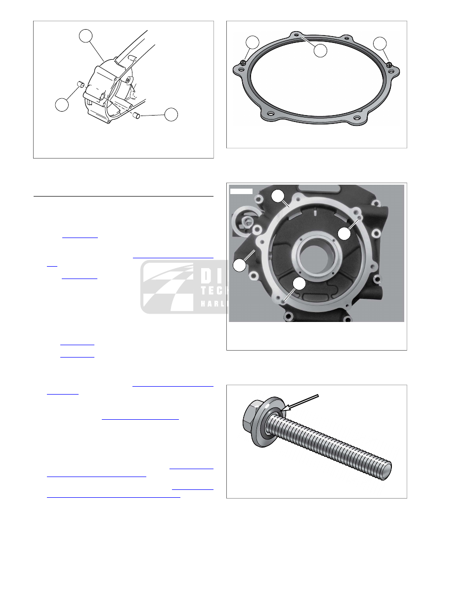
Cover mainshaft clutch hub splines with tape to prevent
the splines damaging the inner primary cover oil seal.

See 

Figure 6-26

. In next step, be sure dowels (1) in

crankcase gasket (2) engage holes in crankcase.

1.

Verify pivot shaft torque. See 

2.22 REAR FORK, Installa-

tion

.

2.

See 

Figure 6-27

. Place crankcase gasket in place on

gasket surface (2). Be sure dowels in gasket engage dowel
holes (3).

3.

Spread a thin film of oil on mainshaft oil seal lip and rubber
portion of crankcase gasket. Be careful not to damage
mainshaft seal when installing chaincase over the primary
bearing inner race on the mainshaft.

4.

See 

Figure 6-28

. Insert new sealing fasteners.

5.

See 

Figure 6-29

Tighten fasteners in sequence shown to

25-27 ft-lbs (33.9-36.6 Nm).

6.

Install the primary chain, clutch, and compensating
sprocket as an assembly. See 

6.3 DRIVE COMPONENTS,

Installation

.

7.

Install chain tensioner assembly.

8.

Install starter. See 

5.2 STARTER, Installation

.

NOTE

The gasket between the primary chaincase cover and chain-
case must be replaced each time the cover is removed. Failure
to replace this gasket may cause primary chaincase leaks .

9.

Install primary chaincase cover. See 

6.2 PRIMARY

CHAINCASE COVER, Installation

.

10. Fill primary chaincase with lubricant. See 

1.9 PRIMARY

CHAIN, Chaincase Lubricant: Touring Models

.

11. Adjust rear belt tension.

12. Connect negative battery cable.

2

1

1

sm02381

1.

Dowel

2.

Crankcase gasket

Figure 6-26. Crankcase Gasket

2

1

3

3

sm02382

1.

Crankcase

2.

Gasket surface

3.

Dowel holes

Figure 6-27. Crankcase

sm02383

Figure 6-28. Sealing Fastener

6-12  2008 Touring Service:  Drive

2

1

4

3

5

6

sm03585

4.

1.

Right side nacelle

Left side nacelle

2.

5.

Clutch cable clip hole

Speaker switch connector [105C]

6.

3.

Instrument nacelle switch connector [105B]

Speaker switch connector [105D]

Figure 8-75. Instrument Nacelle Halves

2.

Push terminals through two lengths of conduit to wire end
of socket or pin housing. For best results, push one wire
through conduit at a time.

3.

Refer to 

Table 8-14

. See 

Figure 8-74

. Install terminals into

socket or pin housing.

NOTE

For instructions on properly installing wire terminals, see

A.2 AMP MULTILOCK CONNECTORS

.

4.

Snap switch bracket into molded retainer in instrument
nacelle.

5.

Install right side of instrument nacelle on motorcycle. See

Figure 8-75

.

6.

See 

Figure 8-72

. Connect speaker switch connector [105],

4-place Multilock.

7.

Connect instrument nacelle switch connector [105], 12-
place Multilock.

8.

Install two screws (with flat washers) to fasten right side
instrument nacelle to upper and lower fork brackets.
Alternately tighten screws to 15-20 ft-lbs (20-27 Nm).

9.

Looking into instrument nacelle, connect instruments and
indicator lights to interconnect harness as follows:

a.

Speedometer connector [39], 12-place Packard.

b.

Tachometer connector [108], 12-place Packard.

c.

Indicator lights connector [21], 10-place Multilock.

8-56  2008 Touring Service:  Electrical

10. Verify that left and right sides of instrument nacelle are

properly mated. Pins on left side of nacelle must fully
engage holes on right.

11. Insert tab at rear of bezel into slot of instrument nacelle

(just in front of ignition switch). Holding left and right sides
of nacelle together, place bezel over instrument nacelle
flange. When properly mated, tabs at front of instrument
nacelle engage lip in slot at front of bezel (behind decor-
ative adhesive strip).

NOTE

If tabs do not properly engage slot at front of bezel, then a
loose fit will result. Remove decorative adhesive strip by gently
prying up outer edges, and using a flat bladed screwdriver,
carefully raise tabs so that they engage lip in slot. If damaged,
install new decorative adhesive strip.

12. Install screw on each side of bezel. Alternately tighten

screws to 25-35 in-lbs (2.8-4.0 Nm).

13. Assemble ignition switch. See 

8.17 IGNITION/LIGHT KEY

SWITCH AND FORK LOCK

.

2008 Touring Service:  Electrical  8-57

8.20

CRANKSHAFT POSITION SENSOR (CKP)

GENERAL

The crank position sensor is a variable reluctance (VR) sensor
that generates an AC signal by sensing the passing of the 30
teeth machined in the left side flywheel. Two consecutive teeth
are missing in the flywheel to establish a reference point. The
crank position sensor sends a signal to the electronic control
module which is used to reference engine position (TDC) and
engine speed.

NOTE

CKP sensor connector is not serviceable. If connector or sensor
fails, the entire assembly must be replaced.

REMOVAL

1.

Remove maxi-fuse. See 

8.5 SYSTEM FUSES AND

RELAYS

.

2.

Locate CKP sensor connector [79], 2-place Deutsch, fixed
to front caddy at bottom of lower frame crossmember.

3.

Push connector toward right side of motorcycle to disen-
gage small end of slot on attachment clip from T-stud on
front caddy. Lift connector off T-stud.

4.

Depress button on socket terminal side and pull apart pin
and socket halves.

5.

Remove screw to free CKP sensor mount from front left
side of crankcase. Pull sensor from bore. See 

Figure 8-76

and 

Figure 8-77

.

INSTALLATION

1.

Install new o-ring on sensor body if missing, distorted,
pinched or otherwise damaged. Apply a thin film of clean
H-D 20W50 engine oil to o-ring before installation.

2.

Push sensor into bore aligning hole in sensor mount with
hole in spot face. Install screw and tighten to 90-120 in-
lbs
 (10.2-13.6 Nm). See 

Figure 8-76

.

3.

Route connector and convoluted tubing downward at rear
of front engine stabilizer link to front caddy at bottom of
lower frame crossmember.

4.

Mate pin and socket halves of CKP sensor connector [79].

sm03463

Figure 8-76. Remove CKP Sensor Mount Screw

sm02543

Figure 8-77. CKP Sensor O-Ring

5.

Place large end of slot on attachment clip over T-stud on
front caddy. Push connector toward left side of motorcycle
to engage small end of slot.

6.

Install maxi-fuse. See 

8.5 SYSTEM FUSES AND RELAYS

.

8-58  2008 Touring Service:  Electrical

8.21

ALTERNATOR

REMOVAL

1.

Remove seat. See 

2.26 SEAT

.

To prevent accidental vehicle start-up, which could cause
death or serious injury, disconnect negative (-) battery
cable before proceeding. (00048a)

2.

Unthread bolt and remove battery negative cable (black)
from battery negative (-) terminal.

3.

Remove the primary chaincase. See 

6.4 PRIMARY

CHAINCASE HOUSING

.

The high-output rotor contains powerful magnets. Exercise
caution to prevent possible hand injury during removal
and installation. (00558b)

4.

Grasp the rotor/spring cover assembly with both hands
and pull from the engine compensating sprocket shaft.
See 

Figure 8-78

.

5.

Loosen locknuts on studs of lower frame crossmember.
Lift voltage regulator and release conduit from P-clip under
left side leg of voltage regulator.

6.

Pull away locking latch and remove socket of stator con-
nector [46], 3-place Lyall, at bottom left side of voltage
regulator. See 

Figure 8-79

.

NOTE

The rubber molded stator connector is not serviceable. Damage
to terminals or molding requires stator and/or voltage regulator
replacement.

7.

Draw stator conduit and socket to rear of front engine
stabilizer link and then up to area in front of primary
chaincase.

8.

Remove four screws to free stator from crankcase. Discard
screws.

9.

Using point of awl, carefully lift capped rib on grommet
away from crankcase and then insert into bore between
grommet and casting. See 

Figure 8-80

. Tilt awl slightly,

squirting isopropyl alcohol or glass cleaner into opening.
Repeat this step at one or two other locations around
grommet.

10. While pushing on capped rib from outside of crankcase,

draw grommet through bore by pulling on cable stop with
needle nose pliers. Rock grommet back and forth to facil-
itate removal, if necessary. Exercise caution to avoid
damaging ribs on grommet if stator is to be reused.

11. Draw conduit and socket through crankcase bore.

sm03513

Figure 8-78. Remove Rotor/Spring Cover Assembly

1

2

sm03468

1.

Stator connector [46]

2.

Voltage regulator

Figure 8-79. Voltage Regulator (Left Side View)

CLEANING AND INSPECTION

1.

Check inside of rotor and remove any metal fragments
captured by magnets.

2.

Clean the rotor using a petroleum solvent. Clean the stator
and grommet by wiping it with a clean cloth.

2008 Touring Service:  Electrical  8-59

3

4

2

1

sm03469

1.

Awl

2.

Capped rib

3.

Opening

4.

Stator

Figure 8-80. Remove Grommet From Crankcase

INSTALLATION

1.

From inside crankcase, feed socket and conduit through
hole in crankcase.

2.

Thoroughly lubricate grommet with isopropyl alcohol or
glass cleaner. Ribs of grommet must be clean and free of
dirt and oily residue.

3.

Carefully grasp cable stop behind grommet with a needle
nose pliers. Push grommet into crankcase bore while
carefully pulling on outside cable. Installation is complete
when cable stop contacts casting and capped rib of
grommet exits crankcase bore.

4.

If necessary, carefully run awl around edge of capped rib
so that it rests flat against seating surface on crankcase.

NOTE

Do not reuse stator mounting screws. The threads of the screws
contain a locking compound in pellet form. When the screw is
started, the pellet breaks, releasing the compound.

5.

Install four new screws to fasten stator to crankcase.
Alternately tighten screws to 55-75 in-lbs (6.2-8.5 Nm).

The high-output rotor contains powerful magnets. Exercise
caution to prevent possible hand injury during removal
and installation. (00558b)

6.

Grasp the rotor/spring cover assembly with both hands
and ease onto the engine compensating sprocket shaft.

7.

Feed socket and conduit under front engine stabilizer link
and then forward along outboard side of voltage regulator
leg. See 

Figure 8-79

.

8.

Capture conduit in P-clip under left side leg of voltage
regulator. Remove slack to ensure that conduit does not
contact front engine stabilizer link.

9.

Install socket of stator connector [46], 3-place Lyall, at
bottom left side of voltage regulator. Push against locking
latch until socket is fully engaged.

10. Alternately tighten locknuts on studs of lower frame

crossmember to 70-100 in-lbs (7.9-11.3 Nm).

11. Install the primary chaincase. See 

6.4 PRIMARY CHAIN-

CASE HOUSING

.

12. Insert bolt through battery negative cable (black) into

threaded hole of battery negative (-) terminal. Tighten bolt
to 60-96 in-lbs (6.8-10.9 Nm).

13. Install seat. See 

2.26 SEAT

.

8-60  2008 Touring Service:  Electrical

8.22

VEHICLE SPEED SENSOR (VSS)

VSS

Removal

1.

Remove starter. See 

5.2 STARTER

.

2.

Disconnect VSS connector [65], 3-place Delphi, at top of
transmission case. See 

Figure 8-81

.

3.

Remove screw and pull sensor from transmission case.

Installation

1.

Inspect VSS O-ring for cuts, tears or general deterioration.
Replace as necessary.

2.

Insert sensor into transmission case. Install screw and
tighten to 84-132 in-lbs (9.5-14.9 Nm).

3.

Connect VSS connector [65], 3-place Delphi.

4.

Install starter. See 

5.2 STARTER

.

sm03705

Figure 8-81. VSS Location

2008 Touring Service:  Electrical  8-61

8.23

NEUTRAL SWITCH

GENERAL

The neutral switch is located on the transmission case. The
two terminal switch is normally closed. When the transmission
shifter is in neutral and the ignition switch is in the IGNITION
position, the switch causes the NEUTRAL indicator light to
illuminate.

REMOVAL

1.

Verify that transmission is in NEUTRAL.

2.

Remove two elbow connectors from neutral switch posts.
See 

Figure 8-82

.

3.

Using open end/box wrench on flats, remove neutral switch
from transmission case.

INSTALLATION

1.

Inspect O-ring for cuts, tears or general deterioration.
Replace as necessary. Lightly lubricate new O-ring with
clean transmission oil before installation. See 

Figure 8-83

.

2.

Roll motorcycle back and forth to verify that transmission
is in NEUTRAL.

3.

Install neutral switch in transmission case. Using open
end/box wrench on flats, tighten to 120-180 in-lbs (13.6-
20.3 Nm).

4.

Install two elbow connectors onto neutral switch posts.

NOTE

The neutral switch is not polarity sensitive, so the elbow con-
nectors can be installed on either post.

5.

Test neutral switch for proper operation. Proceed as fol-
lows:

a.

Roll motorcycle back and forth to verify that transmis-
sion is in NEUTRAL.

b.

Turn Ignition/Light Key Switch to IGNITION.

c.

Verify that neutral indicator light illuminates.

sm05247

Figure 8-82. Neutral Switch

sm05246

Figure 8-83. Neutral Switch O-Ring

8-62  2008 Touring Service:  Electrical

8.24

OIL PRESSURE SWITCH AND SENDER

REMOVAL

1.

Locate the oil pressure switch/sender at the front right side
of the crankcase.

2.

FLHR/C:

a.

Pull elbow connector [120] from post terminal of oil
pressure switch.

b.

Use a 15/16 inch Open End Crow Foot (Snap-on®
FC30B) to remove switch from crankcase.

3.

FLHX, FLHT/C/U, FLTR:

a.

Remove 4-place Delphi connector [139] from oil
pressure sender.

b.

Use 1-1/16 inch Open End Crow Foot (Snap-on®
FC34A) to remove sender from crankcase.

INSTALLATION

NOTE

If reusing oil pressure switch/sender, apply Loctite Pipe Sealant
with Teflon 565 to threads.

1.

Start oil pressure switch/sender into crankcase bore.

2.

FLHR/C:

a.

Use a 15/16 inch Open End Crow Foot (Snap-On
FC30B) to tighten oil pressure switch to 96-120 in-
lbs
 (11-14 Nm).

b.

Install elbow connector [120] onto post terminal.

3.

FLHX, FLHT/C/U, FLTR:

a.

Use 1-1/16 inch Open End Crow Foot (Snap-On
FC34A) to tighten oil pressure sender to 96-120 in-
lbs
 (11-14 Nm).

b.

Install 4-place Delphi connector [139].

4.

Test oil pressure switch/sender for proper operation.

2008 Touring Service:  Electrical  8-63

8.25

STOPLIGHT SWITCHES

FRONT STOPLIGHT SWITCH

Removal/Installation

See 

8.39 HANDLEBAR SWITCH ASSEMBLIES

.

REAR STOPLIGHT SWITCH

Removal

D.O.T. 4 brake fluid will damage painted and body panel
surfaces it comes in contact with. Always use caution and
protect surfaces from spills whenever brake work is per-
formed. Failure to comply can result in cosmetic damage.
(00239b)

NOTE

Immediately wipe up any brake fluid spillage with a clean, dry,
soft cloth. Follow up by thoroughly wiping affected area with a
clean, damp, soft cloth (small spills) or washing with a large
quantity of soapy water (large spills).

1.

Using wrench on flats, remove rear stoplight switch from
rear brake line. See 

Figure 8-84

.

NOTE

Wrap rear brake line with piece of shop towel to absorb any
loss of brake fluid.

Installation

1.

Apply Loctite Pipe Sealant with Teflon 565 to threads of
rear stoplight switch.

2.

Install rear stoplight switch into rear brake line. See

Figure 8-84

.

3.

Using wrench on flats, tighten rear stoplight switch to 12-
15 ft-lbs (16.3-20.3 Nm).

4.

Fill and bleed rear brake system. See 

1.14 BLEEDING

BRAKES

.

Be sure that all lights and switches operate properly before
operating motorcycle. Low visibility of rider can result in
death or serious injury. (00316a)

5.

Verify proper operation of tail lamp/rear brake light.

sm03703

Figure 8-84. Rear Stoplight Switch

8-64  2008 Touring Service:  Electrical

8.26

HORN

INSPECTION

If the horn fails to sound or does not sound satisfactorily, check
for loose, frayed or damaged wires leading to horn terminal,
discharged battery or corroded ground.

The horn is permanently sealed and non-repairable. Only the
mounting hardware is replaceable.

NOTE

No tonal adjustments may be made to this horn.

REMOVAL

1.

Remove acorn nut and flat washer to free horn assembly
from rubber mount stud.

2.

Remove elbow terminals from spade contacts and release
main harness conduit from J-clamp.

3.

Remove flange nut (10mm) from circular recess at back
of horn bracket. Remove horn from chrome horn cover.

INSTALLATION

1.

Fit horn into chrome cover so that stud at back slides
through hole in horn bracket. Apply two drops of Loctite
Low Strength Threadlocker 222 (purple) to threads of horn
stud.

NOTE

Overtightening the flange nut can cause permanent horn
damage resulting in reduced volume and tone quality.

2.

Install flange nut (10mm) on horn stud and tighten to 80-
100 in-lbs (9.0-11.3 Nm).

3.

Install elbow terminals onto spade contacts.

NOTE

The horn is not polarity sensitive. Elbow terminals may be
attached to either spade contact.

4.

Capture main harness conduit in J-clamp and install horn
bracket onto rubber mount stud. Install flat washer and
acorn nut. Tighten acorn nut to 80-120 in-lbs (9.0-13.6
Nm).

2008 Touring Service:  Electrical  8-65

8.27

CIGARETTE LIGHTER: FLHX, FLHT/C/U, FLTR

GENERAL

FLHX, FLHT/C/U and FLTR models are equipped with a
cigarette lighter. The lighter is located on the left side of the
inner fairing.

TROUBLESHOOTING

1.

Ignition/light key switch must be ON or in ACCESSORY
position for lighter operation.

2.

If lighter does not work, substitute a known good lighter
element.

3.

If lighter is still inoperative, check for 12 vdc at center
socket contact and ground at outer shell contact.

4.

Refer to applicable Wiring Diagram at rear of manual if 12
vdc or ground are not present. Use voltage checks to
isolate problem.

REMOVAL

1.

Remove outer fairing. See 

2.35 UPPER FAIRING AND

WINDSHIELD: FLHX, FLHT/C/U

 or 

2.39 UPPER FAIRING

AND WINDSHIELD: FLTR

.

2.

Disconnect socket terminals from spade contacts on
cigarette lighter.

3.

Remove lighter from socket. Holding socket, unscrew outer
shell. Remove socket and outer shell from inner fairing.

INSTALLATION

1.

From rider side of inner fairing, slide socket of new cigar-
ette lighter through bore in fairing. Thread outer shell onto
socket until tight. Install cigarette lighter in socket.

2.

Connect socket terminals onto spade contacts of cigarette
lighter. Connect orange wire terminal to center socket
spade contact, the black wire terminal to outer shell con-
tact.

3.

Install outer fairing. See 

2.35 UPPER FAIRING AND

WINDSHIELD: FLHX, FLHT/C/U

 or 

2.39 UPPER FAIRING

AND WINDSHIELD: FLTR

.

8-66  2008 Touring Service:  Electrical

8.28

GAUGES AND INSTRUMENTS: FLHX, FLHT/C/U,
FLTR

2 INCH DIAMETER GAUGES: FUEL LEVEL,
AMBIENT AIR TEMPERATURE,
VOLTMETER, OIL PRESSURE

Removal

1.

Remove outer fairing. See 

2.35 UPPER FAIRING AND

WINDSHIELD: FLHX, FLHT/C/U

 or 

2.39 UPPER FAIRING

AND WINDSHIELD: FLTR

.

2.

Pull 2-place and 3-place socket housings to release
interconnect harness from lamp and gauge, respectively.

NOTE

To replace lamp, pull pin housing from gauge and then pull
lamp from slot of pin housing. Install new lamp in slot and insert
pin housing back into gauge. See 

Figure 8-85

.

3.

Remove hex nuts from studs. Remove mounting bracket.

4.

Remove gauge from inner fairing.

Installation

1.

Install gauge in inner fairing.

2.

Slide mounting bracket over studs. Verify that tabs on top
and bottom of bracket engage slots in inner fairing. See

Figure 8-85

.

3.

Loosely install hex nuts on studs. Verify that gauge is
properly aligned and then tighten nuts to 10-20 in-lbs (1.1-
2.3 Nm).

4.

Install 3-place and 2-place socket housings to connect
interconnect harness to gauge and lamp, respectively.

5.

Install outer fairing. See 

2.35 UPPER FAIRING AND

WINDSHIELD: FLHX, FLHT/C/U

 or 

2.39 UPPER FAIRING

AND WINDSHIELD: FLTR

.

1

3

6

4

2

5

sm02866

1.

Pin housing

2.

Hex nut

3.

Stud

4.

Mounting bracket

5.

Tab

6.

Gauge

Figure 8-85. 2 Inch Diameter Gauges

TACHOMETER

Removal

1.

Proceed as follows:

a.

FLHX, FLHT/C/U: Remove outer fairing. See

2.35 UPPER FAIRING AND WINDSHIELD: FLHX,
FLHT/C/U

.

b.

FLTR: Remove bezel. See 

2.40 INSTRUMENT

BEZEL: FLTR

.

2.

Remove tachometer connector [108], 12-place Packard,
at back of tachometer.

3.

Remove two screws to free tachometer bracket from back
of tachometer gauge.

4.

Push tachometer gauge toward rear of motorcycle to
remove from inner fairing (FLHX, FLHT/C/U) or bezel bore
(FLTR).

Installation

1.

Insert tachometer gauge into inner fairing (FLHX,
FLHT/C/U) or bezel bore (FLTR).

2.

Align holes in tachometer bracket with those at back of
tachometer gauge and start two screws.

3.

Rotate tachometer gauge until tabs at top and bottom of
bracket engage slots in inner fairing (FLHX, FLHT/C/U)
or bezel (FLTR).

4.

Verify that gauge is properly aligned and tighten two
screws to 10-20 in-lbs (1.1-2.3 Nm).

2008 Touring Service:  Electrical  8-67

5.

Install tachometer connector [108], 12-place Packard, at
back of tachometer.

6.

Proceed as follows:

a.

FLHX, FLHT/C/U:

Install outer fairing. See

2.35 UPPER FAIRING AND WINDSHIELD: FLHX,
FLHT/C/U

.

b.

FLTR: Install bezel. See 

2.40 INSTRUMENT BEZEL:

FLTR

.

SPEEDOMETER

Removal

1.

Proceed as follows:

a.

FLHX, FLHT/C/U: Remove outer fairing. See

2.35 UPPER FAIRING AND WINDSHIELD: FLHX,
FLHT/C/U

.

b.

FLTR: Remove bezel. See 

2.40 INSTRUMENT

BEZEL: FLTR

.

2.

Remove speedometer connector [39], 12-place Packard,
at back of speedometer.

3.

Remove two screws to free speedometer bracket from
back of speedometer gauge. On FLHX, FLHT/C/U models,
leave anchor on interconnect harness installed in lower
ear of speedometer bracket, if present.

4.

Push speedometer gauge toward rear of motorcycle to
remove from inner fairing (FLHX, FLHT/C/U) or bezel bore
(FLTR).

Installation

1.

Insert speedometer gauge into inner fairing (FLHX,
FLHT/C/U) or bezel bore (FLTR).

2.

Align holes in speedometer bracket with those at back of
speedometer gauge and start two screws.

sm03707

Figure 8-86. Anchor Interconnect Harness in Ear of

Speedometer Bracket

3.

Rotate speedometer gauge until tabs at top and bottom
of bracket engage slots in inner fairing (FLHX, FLHT/C/U)
or bezel (FLTR).

4.

Verify that gauge is properly aligned and tighten two
screws to 10-20 in-lbs (1.1-2.3 Nm).

5.

Install speedometer connector [39], 12-place Packard, at
back of speedometer.

6.

Proceed as follows:

a.

FLHX, FLHT/C/U: Verify that anchor on interconnect
harness is installed in lower ear of speedometer
bracket. Install outer fairing. See 

2.35 UPPER

FAIRING AND WINDSHIELD: FLHX, FLHT/C/U

.

b.

FLTR: Install bezel. See 

2.40 INSTRUMENT BEZEL:

FLTR

.

8-68  2008 Touring Service:  Electrical

8.29

INDICATOR LAMPS: FLHX, FLHT/C/U, FLTR

INDICATOR LIGHTS

Removal

NOTE

All models are equipped with Light Emitting Diodes (LED's) in
lieu of indicator lamps. The indicator light assembly is not ser-
viceable. If one LED is bad, the indicator light assembly must
be replaced.

1.

Proceed as follows:

a.

FLHX, FLHT/C/U: Remove outer fairing. See

2.35 UPPER FAIRING AND WINDSHIELD: FLHX,
FLHT/C/U

.

b.

FLTR: Remove bezel. See 

2.40 INSTRUMENT

BEZEL: FLTR

.

2.

Disconnect indicator lights connector [21], 10-place Multi-
lock (black).

3.

On FLHX, FLHT/C/U models, remove tachometer gauge
to access indicator lights assembly. See 

8.28 GAUGES

AND INSTRUMENTS: FLHX, FLHT/C/U, FLTR

.

4.

Release each paddle on lense from pair of index tabs on
indicator lights assembly. See 

Figure 8-87

. Remove lense

from inner fairing (FLHX, FLHT/C/U) or bezel (FLTR), if
damaged.

N

2

1

5

6

3

4

sm02867

1.

Indicator lights connector [21]

2.

Indicator lights assembly

3.

Lens

4.

Paddles

5.

Index tabs

6.

Orientation stamp

Figure 8-87. Indicator Lights Assembly

Installation

1.

Place lense in inner fairing (FLHX, FLHT/C/U) or bezel
(FLTR), if removed. Note position of oil icon on FLTR
models to be sure that lense is right side up. On FLHX,
FLHT/C/U models, slot at bottom of lense engages index
tab in inner fairing to prevent improper orientation.

2.

With the word "TOP" facing upward, engage each paddle
on lense with pair of index tabs on indicator lights
assembly.

3.

Connect indicator lights connector [21], 10-place Multilock
(black).

4.

On FLHX, FLHT/C/U models, install tachometer gauge.
See 

8.28 GAUGES AND INSTRUMENTS: FLHX,

FLHT/C/U, FLTR

.

5.

Proceed as follows:

a.

FLHX, FLHT/C/U:

Install outer fairing. See

2.35 UPPER FAIRING AND WINDSHIELD: FLHX,
FLHT/C/U

.

b.

FLTR: Install bezel. See 

2.40 INSTRUMENT BEZEL:

FLTR

.

2008 Touring Service:  Electrical  8-69

8.30

GAUGES AND INSTRUMENTS: FLHR/C

FUEL GAUGE

Removal

1.

Remove maxi-fuse. See 

8.5 SYSTEM FUSES AND

RELAYS

.

2.

At bottom left side of fuel tank, gently pull on convoluted
tubing to draw fuel gauge connector [117], 4-place Multi-
lock, out of tunnel. Disconnect pin and socket halves.

3.

Remove terminals from pin housing.

NOTE

For instructions on properly removing wire terminals, see

A.2 AMP MULTILOCK CONNECTORS

.

4.

Remove convoluted tubing from wires.

5.

Remove the gauge cap on the top left side of the fuel tank.
Do not twist the cap during removal. Hold the cap firmly
and pull upward just far enough to free the cap from the
fuel tank.

6.

To remove fuel gauge from motorcycle, feed wires and
pin terminals up into drain tube of fuel tank while carefully
raising cap.

7.

If reusing gauge, inspect rubber seal for tears, cuts or
general deterioration. Replace seal if necessary. Install
new seal so that flat side contacts edge of gauge.

Installation

1.

Place new fuel gauge assembly next to discarded unit
and cut wires to proper length.

2.

Crimp new pin terminals onto fuel gauge wires.

NOTE

For instructions on crimping wire terminals, see 

A.2 AMP

MULTILOCK CONNECTORS

.

3.

While carefully lowering cap, feed wires down into drain
tube until pin terminals exit hole at bottom of fuel tank.
Gently pull wires (to remove slack) while installing the fuel
gauge cap on the fuel tank. Do not twist the cap during
installation. Hold the cap firmly and press downward until
it snaps in place.

4.

Install convoluted tubing on wires.

5.

Install terminals into pin housing of 4-place Multilock.

NOTE

For instructions on properly installing wire terminals, see

A.2 AMP MULTILOCK CONNECTORS

.

6.

Route pin housing and convoluted tubing forward and then
inboard between front of crossover hose fitting and bottom
of fuel tank. Connect fuel gauge connector [117], 4-place
Multilock. Feed connector into tunnel of fuel tank. See
lower frame of 

Figure 8-88

.

7.

Install maxi-fuse. See 

8.5 SYSTEM FUSES AND RELAYS

.

sm02975

Figure 8-88. Fuel Gauge (FLHR/C)

Table 8-15. FLHR/C Fuel Gauge [17]

CHAMBER NUMBER

WIRE COLOR

1

Orange

2

Yellow/White

3

-

4

Black

SPEEDOMETER

Removal

1.

Remove maxi-fuse. See 

8.5 SYSTEM FUSES AND

RELAYS

.

2.

Remove seat. See 

2.26 SEAT

.

3.

Remove socket screw to release front of console from fuel
tank weldment.

4.

Remove hex screw to release rear console bracket from
clip nut on rear fuel tank bracket.

5.

Lay a clean shop towel on forward part of rear fender.
Remove console and lay upside down on shop towel.

6.

Remove speedometer connector [39], 12-place Packard.
If necessary, bend back flexible metal clips to free con-
nector conduit. See 

Figure 8-89

.

7.

Gently pry three latches upward to release lock ring from
back of speedometer.

8.

Remove speedometer from top side of console.

9.

Remove rubber gasket from console speedometer bore.

8-70  2008 Touring Service:  Electrical


Content      ..     38      39      40      41     ..