Harley Davidson 2008 Touring Models. Service Manual - page 36
A
2
1
sm04030
1.
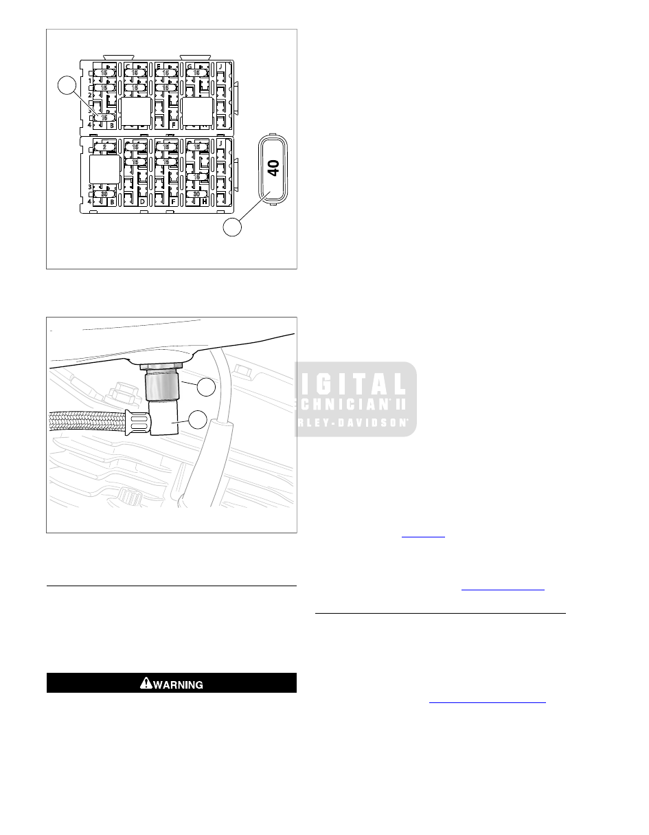
Fuel pump fuse
2.
Maxi-fuse
Figure 4-2. Fuse Blocks
1
2
sm04502
1.
Quick connect fitting (chrome sleeve)
2.
Fuel supply line fitting
Figure 4-3. Fuel Tank (Left Side View)
INSTALLATION
1.
Install fuel tank onto frame backbone aligning front flange
holes with bosses on left and right side of frame. Be sure
that ignition coil connector conduit exiting front left side of
wire trough does not become pinched between fuel tank
flange and ignition coil bracket.
2.
Start front fuel tank screws.
To prevent spray of fuel, be sure quick-connect fittings
are properly mated. Gasoline is extremely flammable and
highly explosive, which could result in death or serious
injury. (00268a)
3.
Pull up on chrome sleeve of quick-connect fitting and insert
neck of fuel supply line fitting. While pushing up on bottom
of fitting, pull down on chrome sleeve. A slight tug on the
fuel supply line fitting will verify that it is locked in position.
4.
On FLHR/C models, move to bottom left side of fuel tank.
Mate pin and socket halves of fuel gauge connector [117],
4-place Multilock. Feed connector into tunnel at front of
fuel tank.
5.
Install two screws to fasten rear fuel tank bracket to frame
backbone. Alternately tighten screws to 15-20 ft-lbs (20.3-
27.1 Nm). Install plastic trim cover over bracket.
6.
Alternately tighten front fuel tank screws to 15-20 ft-
lbs (20.3-27.1 Nm). Install rubber caps over screws.
Properly installed, relief on inboard side of cap is at the
bottom and lip is inboard of frame boss flange.
7.
Connect fuel vapor vent tube to vapor valve fitting on top
plate.
8.
Install fuel level sender/fuel pump connector [141], 4-place
Delphi. For best clearance with cam ring, tilt connector at
35° angle before installation.
9.
Install console. Proceed as follows:
a.
FLHR/C: Exercising caution to avoid pinching wire
harness and vent tube, position console on fuel tank.
b.
FLHX, FLHT/C/U, FLTR: Remove filler cap, if
installed. Exercising caution to avoid pinching wire
harness, fuel overflow hose and vent tube, position
console on fuel tank. Install filler cap.
c.
Start socket screw to fasten front of console to fuel
tank weldment.
d.
Start hex screw to fasten rear console bracket to clip
nut on rear fuel tank bracket.
e.
Alternately tighten socket/hex screws to 36-60 in-
lbs (4.1-6.8 Nm).
NOTE
If console rear bracket requires replacement, install new
bracket alternately tightening two screws to 20-30 in-
lbs (2.7-3.4 Nm).
10. Install seat. See
.
11. Install maxi-fuse.
12. Install left side cover.
13. Install left side saddlebag. See
FUEL SUPPLY CHECK VALVE/TUBE
Removal
NOTE
The in-tank check valve is housed in the quick-connect fitting.
The check valve prevents the fuel tank from draining when the
external supply line is disconnected.
1.
Remove top plate. See
4-6 2008 Touring Service: Fuel System