Harley Davidson 2008 Touring Models. Service Manual - page 37
 

  Главная      Harley Davidson     Harley Davidson 2008 Touring Models. Service Manual


Search            copyright infringement  


Content      ..     35      36      37      38     ..


Harley Davidson 2008 Touring Models. Service Manual - page 37


8

1

2

3

4

5

6

7

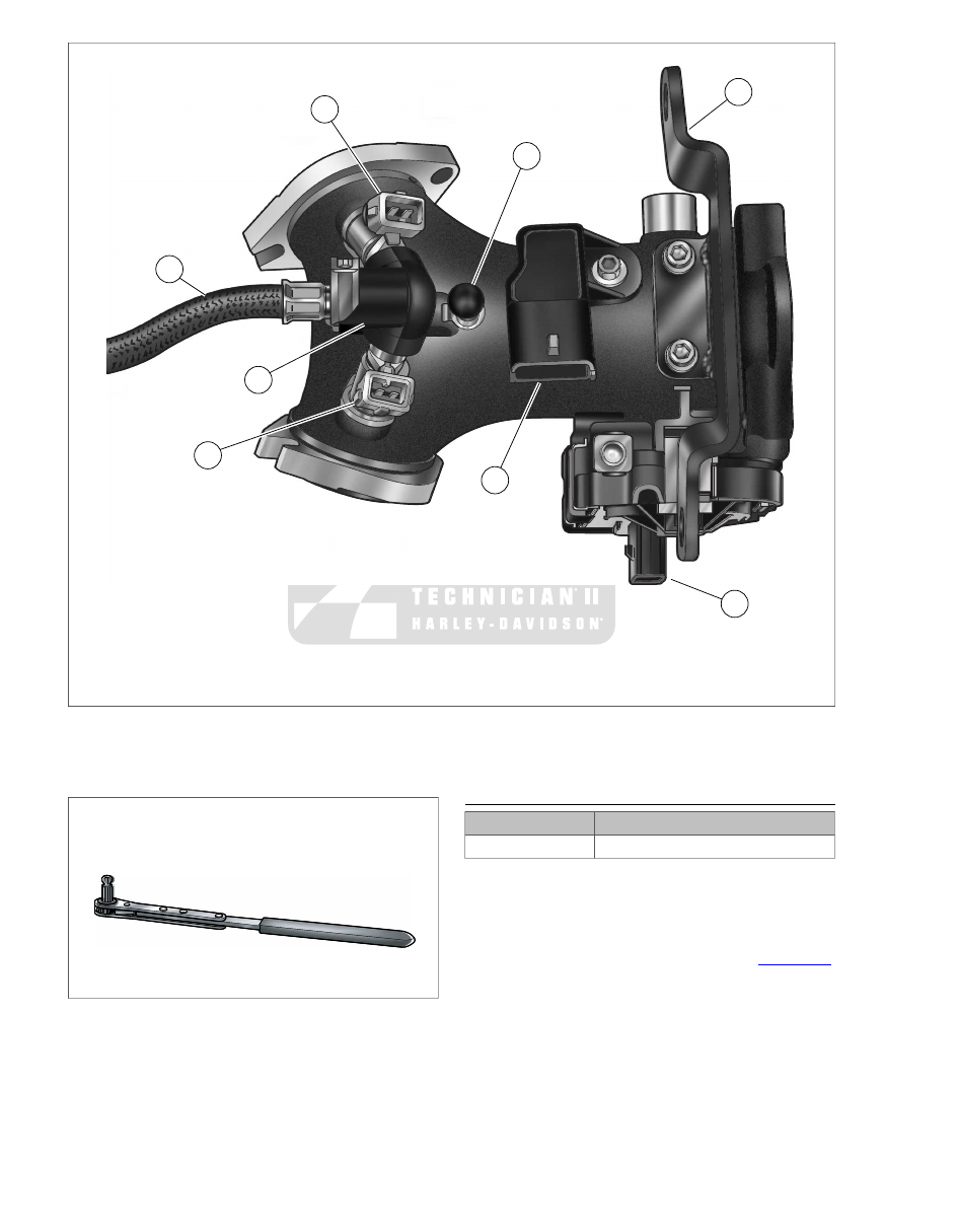
sm04089

5.

1.

T-MAP sensor [80]

Front fuel injector [84]

2.

6.

Purge tube fitting/cap

Rear fuel injector [85]

7.

3.

Fuel rail

Mounting bracket

4.

8.

TCA [211]

Fuel supply tube

Figure 4-26. Induction Module Assembly

sm04384

Figure 4-27. Intake Manifold Wrench (HD-47250)

INSTALLATION

TOOL NAME

PART NUMBER

INTAKE MANIFOLD WRENCH

HD-47250

1.

With the counterbore facing outward, slide cylinder head
flange adapters onto outlet ports of induction module.

2.

Place a new seal in each flange adapter with the beveled
side in against the counterbore.

3.

Orient the induction module as shown in 

Figure 4-26

.

Standing on right side of motorcycle, slide induction
module toward installed position so that open-ended slots
on flange adapters engage socket screws loosely installed
on left side.

4.

Align fixed holes in flange adapters with holes in cylinder
heads and start socket screws. For best results, use the
INTAKE MANIFOLD WRENCH (Part No. HD-47250).

4-22  2008 Touring Service:  Fuel System

5.

Use mounting bracket to properly locate induction module.
Start two breather bolts to fasten mounting bracket to front
and rear cylinder heads.

6.

Tighten socket screws in fixed holes of flange adapters
until snug. Moving to left side, tighten screws in slotted
holes to 96-144 in-lbs (10.9-16.3 Nm).

7.

Tighten socket screws in fixed holes of flange adapters to
96-144 in-lbs (10.9-16.3 Nm).

8.

If parts were removed for access to left side flange adapter
screws, proceed as follows:

a.

Install ET sensor connector [90] at back of front cyl-
inder. Pull boot over sensor to keep out dirt and
debris.

b.

Install elbow terminals onto horn spade contacts.
Capture harness conduit in J-clamp.

c.

Install screw (with flat washer) to fasten horn bracket
to rear cylinder head. Alternately tighten front and
rear horn bracket screws to 35-40 ft-lbs  (48-54 Nm).

9.

Remove breather bolts to release mounting bracket from
front and rear cylinder heads.

10. Install rear fuel injector connector [85] and front fuel

injector connector [84].

11. Install T-MAP sensor connector [80].

12. Route TCA connector and conduit straight down between

induction module and front cylinder staying inboard of
mounting bracket. Install new anchored cable strap in hole
at front right side of induction module and loosely capture
TCA conduit.

13. Route conduit rearward under induction module and install

TCA connector [211]. Tighten cable strap and cut any
excess cable strap material.

14. Connect purge tube to fitting at top of induction module

(California models only). On non-California models, inspect
rubber cap for tears, cracks or signs of deterioration.
Replace cap if damaged or missing. Operation without
cap can result in engine damage.

15. Install fuel tank. See 

4.4 FUEL TANK

.

16. Install backplate and air cleaner. See 

4.3 AIR CLEANER

ASSEMBLY

.

2008 Touring Service:  Fuel System  4-23

4.13

MANIFOLD ABSOLUTE PRESSURE SENSOR
(MAP)

GENERAL

Refer to the ELECTRICAL DIAGNOSTIC MANUAL for
information on the function and testing of the temperature/man-
ifold absolute pressure (T-MAP) sensor.

REMOVAL

1.

Remove fuel tank. See 

4.4 FUEL TANK

.

2.

Remove hex screw to release T-MAP sensor bracket from
induction module. Discard screw.

3.

While rotating T-MAP sensor slightly, pull straight up to
release pressure port from hole in induction module. See

Figure 4-28

.

sm04080

Figure 4-28. T-MAP Sensor

INSTALLATION

1.

Inspect o-ring on pressure port for cuts, tears or signs of
deterioration. Install new o-ring if necessary.

2.

With the electrical connector facing toward the rear of the
induction module, insert pressure port on T-MAP sensor
into hole in induction module.

3.

Align hole in T-MAP sensor bracket with threaded hole in
induction module.

4.

Install new hex screw and tighten to 84-108 in-lbs (9.5-
12.2 Nm).

5.

Install fuel tank. See 

4.4 FUEL TANK

.

4-24  2008 Touring Service:  Fuel System

4.14

OXYGEN SENSORS (O2)

GENERAL

Refer to the ELECTRICAL DIAGNOSTIC MANUAL for
information on the function and testing of the oxygen sensor
(O2).

REMOVAL

TOOL NAME

PART NUMBER

O2 SENSOR SOCKET

HD-48262

1.

Remove maxi-fuse. See 

8.5 SYSTEM FUSES AND

RELAYS

.

2.

Front Exhaust Header: Cut cable strap and disconnect
front O2 sensor connector [138], 2-place Amp (Tyco), at
back of cross brace between front frame downtubes (left
side).

3.

Rear Exhaust Header: Disconnect rear O2 sensor con-
nector [137], 2-place Amp (Tyco), under chrome starter
cover.

4.

Obtain O2 SENSOR SOCKET (Part No. HD-48262) with
drive extension. See 

Figure 4-29

.

5.

Positioned on left side of motorcycle, slide socket over
sensor body hex on inboard side of exhaust header and
turn counterclockwise to loosen. See 

Figure 4-30

.

6.

When sensor turns easily, pull out socket and remove
sensor by hand. See 

Figure 4-31

.

sm04321

Figure 4-29. O2 Sensor Socket (HD-48262)

sm04503

Figure 4-30. Remove/Install Front O2 Sensor

sm04320

Figure 4-31. Front O2 Sensor

INSTALLATION

NOTE

Do not reuse sensors that have been dropped or impacted by
other components. Damage to the sensing element may have
occurred.

1.

If reusing O2 sensor, proceed as follows:

a.

Install new seal washer.

b.

Apply a light coating of Loctite Anti-Seize Lubricant
(Part No. 98960-97) to threads. Use of any other
grease or sealant can result in signal trouble and
sensor failure.

NOTE

Anti-seize is applied to the threads of new sensors at the
factory.

2.

Positioned on left side of motorcycle, hand start O2 sensor
into threaded boss on inboard side of exhaust header.

2008 Touring Service:  Fuel System  4-25

3.

Obtain O2 SENSOR SOCKET (HD-48262) with drive
extension. Slide socket over sensor body hex and tighten
to 30-44 ft-lbs  (40.7-59.7 Nm).

NOTE

Do not apply dielectric grease, cleaning agents, or any other
lubricants, sealants or fluids to O2 sensor connectors. Any
such application will result in signal trouble and sensor failure.

4.

Front Exhaust Header: Connect front O2 sensor con-
nector [138], 2-place Amp (Tyco). Install new cable strap

to secure connector to back of cross brace between front
frame downtubes (left side). Cut any excess cable strap
material.

5.

Rear Exhaust Header: Connect rear O2 sensor connector
[137], 2-place Amp (Tyco), and tuck under chrome starter
cover.

6.

Install maxi-fuse. See 

8.5 SYSTEM FUSES AND RELAYS

.

4-26  2008 Touring Service:  Fuel System

4.15

FUEL INJECTORS

GENERAL

Stop the engine when refueling or servicing the fuel
system. Do not smoke or allow open flame or sparks near
gasoline. Gasoline is extremely flammable and highly
explosive, which could result in death or serious injury.
(00002a)

Refer to the ELECTRICAL DIAGNOSTIC MANUAL for
information on the function and testing of the fuel injectors.

REMOVAL

1.

Remove induction module. See 

4.12 INDUCTION

MODULE

.

2.

Remove T25 TORX screw to release fuel supply tube
clamp from fuel rail.

3.

Rotate fuel supply tube clamp 90° in a clockwise direction
and then remove from groove in fuel supply tube fitting.
See 

Figure 4-32

.

4.

Pull fuel supply tube from fuel rail bore and remove two
o-rings and two sealing washers. Discard o-rings and
sealing washers.

5.

Pull fuel injectors with attached fuel rail from induction
module. To overcome the resistance of the bottom o-ring
on both fuel injectors, gently rock assembly back and forth
while pulling.

6.

Pull fuel injectors from fuel rail. To overcome the resistance
of the top o-ring, gently rock each fuel injector while pulling.

7.

Remove o-rings from fuel injectors. Discard o-rings.

sm04095

Figure 4-32. Rotate Fuel Supply Tube Clamp

INSTALLATION

1.

Apply a very light film of clean engine oil to new o-rings.
Install o-rings on fuel injectors.

2.

Push open end of fuel injectors (opposite cone spray) into
fuel rail.

3.

Rotate fuel injectors, so that the electrical connectors are
on the outboard side. Push cone spray end of fuel injectors
into bores of induction module until slot at bottom of fuel
rail engages machined tab at top of induction module.

4.

Install new o-ring and sealing washer in fuel rail bore.
Install second o-ring and second sealing washer.

5.

Push fuel supply tube into fuel rail bore.

6.

Rotate fuel supply tube in a clockwise direction until
tapered end of quick connect fitting is pointing upward.
Now rotate tube an additional 90°, so that fitting is pointing
rearward (toward TCA on induction module).

7.

Engage slot on fuel supply tube clamp in groove of fuel
supply tube fitting. Rotate fuel supply tube clamp 90° in a

2008 Touring Service:  Fuel System  4-27

counter-clockwise direction until curled lip on fuel supply
tube clamp engages flange on fuel rail.

8.

Align thru holes in fuel rail and fuel supply tube clamp with
threaded hole in induction module. Install T25 TORX screw
and tighten to 66-82 in-lbs (7.5-9.3 Nm).

9.

Install induction module.

4.12 INDUCTION MODULE

.

4-28  2008 Touring Service:  Fuel System

4.16

FUEL PUMP

GENERAL

When servicing the fuel system, do not smoke or allow
open flame or sparks in the vicinity. Gasoline is extremely
flammable and highly explosive, which could result in
death or serious injury. (00330a)

Carefully inspect tubes for cuts, tears, holes or other damage.
Replace fuel pump if any damage is found. Even a small hole
can cause a reduction in fuel pressure.

Refer to the electrical diagnostic manual for information on the
function and testing of the fuel pump.

REMOVAL

1.

Remove top plate. See 

4.5 FUEL TANK TOP PLATE

.

2.

Remove fuel level sender. See 

4.8 FUEL LEVEL SENDER

.

3.

Pull up on transfer tube bracket to release two tabs at
bottom from slots at top of fuel pump bracket.

4.

Depress collar on each side of fitting to disconnect transfer
tube from transfer tube bracket.

5.

Reaching into fuel tank, pull up on rear finger and slide
fuel pump bracket forward until four ears on bracket are
free of catches at top of tunnel. See 

Figure 4-33

.

6.

Remove fuel pump from left side of fuel tank. For best
results, rotate fuel pump assembly 90° in a clockwise dir-
ection until transfer tube connection is pointing rearward,
and then pull from fuel tank. See 

Figure 4-34

.

7.

If necessary, further disassemble fuel pump assembly as
follows:

a.

Reaching into fuel tank, release transfer tube from
weld clip on right side of tunnel and remove from fuel
tank.

b.

Depress arms on fuel inlet strainer and remove from
slots in fuel pump housing.

c.

Inspect the condition of the fuel pump wiring. If the
wiring needs to be replaced, see 

4.16 FUEL PUMP,

Fuel Pump and Fuel Level Sender Wire Harness

.

3

1

2

sm04402

1.

Fuel pump bracket (rear finger)

2.

Transfer tube/bracket

3.

Fuel pump to fuel filter fitting

Figure 4-33. Rear Finger (Fuel Pump Bracket)

sm04404

Figure 4-34. Fuel Pump Assembly

INSTALLATION

1.

If removed, assemble fuel pump assembly as follows:

a.

Reaching into fuel tank, capture transfer tube in weld
clip on right side of tunnel.

b.

Install fuel inlet strainer at bottom of fuel pump enga-
ging arms in slots of fuel pump housing.

2.

Install fuel pump into left side of fuel tank. For best results,
hold fuel pump assembly, so that transfer tube connection
is pointing rearward, and then insert into fuel tank. Now
rotate assembly 90° in a counter-clockwise direction.

3.

Look into fuel tank to verify that fuel inlet strainer lies flat
and that ends are not folded under fuel pump. Also verify
that wire harness is still captured in molded clip at front of
fuel pump bracket.

2008 Touring Service:  Fuel System  4-29

4.

With the finger on the fuel pump bracket pointing rearward,
engage four ears on bracket with rear set of catches at
top of tunnel. Push fuel pump bracket rearward until ears
are fully engaged.

5.

Install transfer tube onto transfer tube bracket. Fit two tabs
at bottom of transfer tube bracket into slots at top of fuel
pump bracket. Verify that transfer tube is still captured in
weld clip on right side of tunnel and that free end is in
contact with bottom of fuel tank.

6.

Install fuel level sender. See 

4.8 FUEL LEVEL SENDER

.

7.

Install top plate. See 

4.5 FUEL TANK TOP PLATE

.

FUEL PUMP AND FUEL LEVEL SENDER
WIRE HARNESS

Removal

NOTE

Damaged wiring, terminals and/or connectors requires
replacement of the wire harness. Do not replace the special
teflon coated wiring with ordinary bulk wire. Ordinary insulation
materials may deteriorate when in contact with gasoline.

1.

Remove fuel pump. See 

4.16 FUEL PUMP

.

2.

Cut cable strap to release wire harness and both fuel pump
and transfer tubes from arm of fuel pump bracket.

3.

Release wire harness from molded clip at front of fuel
pump bracket.

4.

Remove connector at top of fuel pump.

Installation

1.

Install connector at top of fuel pump.

2.

Route wire harness rearward and then forward under arm
of fuel pump bracket. Install new cable strap at elbow
capturing fuel pump and transfer tubes at top of arm and
wire harness at bottom. See 

Figure 4-35

.

3.

Route wire harness through molded clip at front of fuel
pump bracket. See 

Figure 4-36

.

4.

Install fuel pump. See 

4.16 FUEL PUMP

.

sm04405

Figure 4-35. Cable Wires in Cable Strap

sm04406

Figure 4-36. Capture Wires in Molded Clip

4-30  2008 Touring Service:  Fuel System

4.17

FUEL PRESSURE TEST

GENERAL

See 

Figure 4-37

The fuel pump fuse is located in the fuse

block under the left side cover. The fuel pump can be turned
on with Digital Technician or by applying battery voltage to the
fuel pump fuse.

Improper fuel system pressure may contribute to one of the
following conditions:

Cranks, but won't run.

Cuts out (may feel like ignition problem).

Hesitation, loss of power or poor fuel economy.

NOTE

Refer to the electrical diagnostic manual for further information
on the function and testing of the fuel system.

A

sm04505

Figure 4-37. Fuel Pump Fuse

TESTING

TOOL NAME

PART NUMBER

FUEL PRESSURE GAUGE

HD-41182

FUEL PRESSURE GAUGE ADAPTER

HD-44061

The fuel pressure gauge (0-100 PSI) allows for fuel injector
and fuel system pressure diagnosis. Special adapters allow
the gauge to be attached to the external fuel supply line.

Avoid kinking the fuel supply line when installing/removing the
fuel pressure gauge and adapters.

To prevent spray of fuel, purge system of high-pressure
fuel before supply line is disconnected. Gasoline is
extremely flammable and highly explosive, which could
result in death or serious injury. (00275a)

1.

Purge the fuel supply line as follows:

a.

Remove left side saddlebag. See 

2.27 SADDLE-

BAGS

.

b.

Remove left side cover.

c.

Remove 15 amp fuel pump fuse.

d.

Start the engine and allow the motorcycle to run.

e.

When the engine stalls, operate starter for 3 seconds
to remove remaining fuel from fuel supply line.

2.

Locate quick-connect fitting on left side of fuel tank. Pull
up on chrome sleeve and pull down on fuel supply line
fitting to disconnect.

NOTE

Use of two fuel pressure gauge adapters is required. Using
only one adapter will cause excessive twisting of the fuel supply
line.

3.

Install fuel pressure gauge adapters as follows:

a.

Push up on knurled sleeve of FUEL PRESSURE
GAUGE ADAPTER (Part No. HD-44061), insert neck
of second adapter, and then pull down on knurled
sleeve until locked. Tug on adapters to be sure that
they will not come free. See 

Figure 4-38

.

b.

Pull up on knurled sleeve of fuel pressure gauge
adapter, insert neck of fuel supply line fitting, and then
pull down on knurled sleeve until locked. Gently tug
on fuel supply line fitting to be sure that it will not
come free.

c.

Pull up on chrome sleeve of quick-connect fitting on
fuel tank, insert neck of fuel pressure gauge adapter,
and then pull down on chrome sleeve until locked.
Gently tug on adapter to be sure that it will not come
free.

sm02625

Figure 4-38. Fuel Pressure Gauge Adapters

2008 Touring Service:  Fuel System  4-31

1

4

3

5

2

sm02626

1.

Fuel supply line

2.

Adapter to fuel line

3.

Adapter to fuel tank

4.

Pressure adapter Schroeder valve union

5.

Fuel valve (closed position)

Figure 4-39. Fuel Line

sm02627

Figure 4-40. Fuel Pressure Gauge Installed (Typical)

To prevent spray of fuel, be sure quick-connect fittings
are properly mated. Gasoline is extremely flammable and
highly explosive, which could result in death or serious
injury. (00268a)

4.

Verify that the fuel valve and air bleed petcock on the
FUEL PRESSURE GAUGE (Part No. HD-41182) are
closed.

5.

Remove protective cap from Schroeder valve on fuel
pressure gauge adapter closest to the fuel tank. Connect
fuel pressure gauge to Schroeder valve. See 

Figure 4-39

.

6.

Install fuel pump fuse.

7.

Start and idle engine to pressurize the fuel system. Open
the fuel valve to allow the flow of fuel down the hose of
the pressure gauge.

8.

Position the clear air bleed tube in a suitable container
and open and close the air bleed petcock to purge the
gauge and hose of air. Repeat this step several times until
only solid fuel (without bubbles) flows from the air bleed
tube. Close the petcock.

9.

Open and close the throttle to change engine speed. Note
the reading of the pressure gauge. Fuel pressure should
remain steady at  55-62 psi (380-425 kPa).

NOTE

If the fuel pressure is not within specification, see electrical
diagnostic manual for further diagnosis.

10. Turn the engine off. Position the air bleed tube in a suitable

container. Open the air bleed petcock to relieve the fuel
system pressure and purge the fuel pressure gauge of
gasoline.

Gasoline can drain from the adapter when gauge is
removed. Gasoline is extremely flammable and highly
explosive, which could result in death or serious injury.
Wipe up spilled fuel immediately and dispose of rags in a
suitable manner. (00254a)

11. Remove fuel pressure gauge from Schroeder valve. Install

protective cap.

Gasoline can drain from the fuel line and adapter when
removed. Gasoline is extremely flammable and highly
explosive, which could result in death or serious injury.
Wipe up spilled fuel immediately and dispose of rags in a
suitable manner. (00255a)

12. Pull up on knurled sleeve of fuel pressure gauge adapter

and remove fuel supply line fitting. Pull up on chrome
sleeve of quick-connect fitting on fuel tank and remove
fuel pressure gauge adapter.

To prevent spray of fuel, be sure quick-connect fittings
are properly mated. Gasoline is extremely flammable and
highly explosive, which could result in death or serious
injury. (00268a)

13. Pull up on chrome sleeve of quick-connect fitting, insert

neck of fuel supply line fitting, and then pull down on
chrome sleeve until locked. Gently tug on fuel supply line
fitting to be sure that it will not come free.

14. Install left side cover.

15. Install left side saddlebag. See 

2.27 SADDLEBAGS

.

4-32  2008 Touring Service:  Fuel System

4.18

EXHAUST SYSTEM

REMOVAL

NOTE

To access engine and/or transmission components, use the
following procedure to remove the exhaust with minimal disas-
sembly. To completely disassemble the exhaust system, see

4.18 EXHAUST SYSTEM, Disassembly

.

1.

Remove saddlebags. See 

2.27 SADDLEBAGS

.

2.

Remove seat. See 

2.26 SEAT

.

3.

On Ultra models, remove fairing lowers. See 

2.34 LOWER

FAIRING AND ENGINE GUARD

.

4.

Remove two allen head socket screws (with lockwashers
and flat washers) to release right side front footboard
brackets from frame weldment. For best results, approach
from left side of motorcycle using a 3/8 inch ball allen with
extension.

5.

On HDI models, disconnect cable to exhaust valve actuator
as follows:

a.

Locate active exhaust valve just forward of the right
side muffler. Push cam rearward to remove tension
from cable, and then release ball end from slot.

b.

Remove cable clip from slotted flange at front of active
exhaust valve.

6.

Cut cable strap and disconnect front O2 sensor connector
[138], 2-place Amp (Tyco), at back of cross brace between
front frame downtubes (left side). Disconnect rear O2
sensor connector [137] under chrome starter cover.

7.

See 

Figure 4-41

. Remove exhaust system in two sections

as follows:

a.

Open worm drive clamps to release heat shield over
rear header pipe to crossover pipe connection (above
starter).

b.

Loosen TORCA clamp (special) between rear header
pipe and crossover pipe. Remove Keps nut and pull
bracket tab and stud from slots in TORCA clamp and
exhaust support bracket, respectively.

c.

Spray PB Blaster or other suitable penetrating oil in
and around joint between rear header pipe and cros-
sover pipe.

d.

Moving to left side of motorcycle, remove two screws
(with lockwashers) to detach left side muffler from the
lower saddlebag support rail.

e.

Pull and twist on crossover pipe to remove left side
exhaust from motorcycle. For best results, be sure to
allow sufficient time for the penetrating oil to work.

f.

Remove TORCA clamp from crossover pipe. Discard
TORCA clamp.

g.

Moving to right side of motorcycle, open worm drive
clamps and release heat shield from front header
pipe. Using an impact wrench with long 1/2 inch swivel
socket, remove two exhaust flange nuts to release
front header pipe from studs of front cylinder head.
Slide exhaust flange down header pipe to improve
clearance around exhaust port.

h.

Open worm drive clamps and release heat shield from
rear header pipe. Remove two exhaust flange nuts
to release rear header pipe from studs of rear cylinder
head.

i.

Open worm drive clamps to release heat shield over
front header pipe to rear header pipe connection
(outboard of transmission side door).

j.

Remove carriage bolt (with flange locknut) to release
exhaust bracket clamp from transmission exhaust
bracket. Use a channel lock to open clamp and then
remove from front header pipe, if necessary.

k.

Remove two screws (with lockwashers) to detach
right side muffler from the lower saddlebag support
rail.

l.

Depressing rear brake pedal, remove right side
exhaust from motorcycle.

m. Remove and discard gaskets from front and rear

exhaust ports.

2008 Touring Service:  Fuel System  4-33

1

12

25

9

2

11

10

8

7

6

24

3

5

16

17

15

14

13

10

11

20

21

22

23

19

1

1

1

4

18

sm04352

14.

1.

Flange nut (4)

Worm drive clamp (10)

2.

15.

Heat shield, crossover pipe

Exhaust flange (2)

16.

3.

Circlip (2)

Crossover pipe

4.

17.

Rear header pipe

Cylinder head gasket (2)

18.

5.

Heat shield, rear header pipe

TORCA clamp (special)

6.

19.

Keps nut

Heat shield, front header to rear header pipe

20.

7.

Carriage bolt

Bracket tab

8.

21.

Exhaust support bracket

Transmission exhaust bracket

22.

9.

Exhaust bracket clamp

Left muffler

10.

23.

Screw (4)

Flange locknut

24.

11.

Right muffler

Lockwasher (4)

12.

25.

Heat shield, front header pipe

O2 Sensor (2)

13. Front header pipe

Figure 4-41. Remove/Install Exhaust System

INSTALLATION

1.

Install new gaskets in both the front and rear cylinder head
exhaust ports (with the tapered side out).

2.

Place right side exhaust into position on motorcycle and
start two exhaust flange nuts to secure front header pipe
to studs of front cylinder head.

3.

Start two screws (with lockwashers) to secure right side
muffler to the lower saddlebag support rail.

Start two exhaust flange nuts to secure rear header pipe
to studs of rear cylinder head.

4.

Capture front header pipe in exhaust bracket clamp, if
necessary. Use a channel lock to close clamp. Install
carriage bolt engaging transmission exhaust bracket and
exhaust bracket clamp. Finger tighten flange locknut.

5.

Moving to left side of motorcycle, slide new TORCA clamp
(special) onto crossover pipe.

6.

Twist and push crossover pipe onto right side exhaust.

7.

Start two screws (with lockwashers) to secure left side
muffler to the lower saddlebag support rail.

4-34  2008 Touring Service:  Fuel System

8.

Position TORCA clamp (special) between rear header
pipe and crossover pipe. Fit bracket tab into slot of TORCA
clamp engaging stud in slot of exhaust support bracket.
Start Keps nut on stud.

NOTE

Verify that the exhaust pipes do not contact the motorcycle
frame or any mounted components. Contact will cancel the
effect of the rubber isolation mounts and transmit vibration to
the rider.

9.

Tighten the exhaust system as follows:

a.

Using a long 1/2 inch swivel socket, tighten the top
nut of the front cylinder head exhaust flange to 9-18
in-lbs (1-2 Nm). Tighten the bottom nut to 100-120
in-lbs (11.3-13.6 Nm). Final tighten the top nut to
100-120 in-lbs (11.3-13.6 Nm).

b.

Tighten the bottom nut of the rear cylinder head
exhaust flange to 9-18 in-lbs (1-2 Nm). Tighten the
top nut to 100-120 in-lbs (11.3-13.6 Nm). Final tighten
the bottom nut to 100-120 in-lbs (11.3-13.6 Nm).

c.

Tighten flange locknut on exhaust bracket clamp
carriage bolt to 20-25 ft-lbs (27.1-33.9 Nm).

d.

Snug two screws (with lockwashers) holding the right
side muffler to the lower saddlebag support rail.
Alternately tighten screws to 96-144 in-lbs (10.8-16.3
Nm).

e.

Snug two screws (with lockwashers) holding the left
side muffler to the lower saddlebag support rail.
Alternately tighten screws to 96-144 in-lbs (10.8-16.3
Nm).

f.

Verify that all exhaust pipes are in alignment and do
not contact the motorcycle frame or mounted compon-
ents.

g.

Tighten the TORCA clamp (special) between the rear
header pipe and crossover pipe to 45-60 ft-lbs (61-81
Nm).

h.

Tighten Keps nut on stud of bracket tab to 12-15 ft-
lbs (16.3-20.3 Nm).

NOTE

Verify that the heat shields do not contact the motorcycle frame
or any mounted components. Contact will cancel the effect of
the rubber isolation mounts and transmit vibration to the rider.

10. Open worm drive clamps and install heat shields as fol-

lows:

a.

Over front header pipe (below exhaust port).

b.

Over rear header pipe (below exhaust port).

c.

Over front header pipe to rear header pipe connection
(outboard of transmission side door).

d.

Over rear header pipe to crossover pipe connection
(above starter).

11. Position each worm drive clamp so that screw is on the

outboard side in the most accessible position and then
tighten to 20-40 in-lbs (2.3-4.5 Nm).

12. Connect front O2 sensor connector [138], 2-place Amp

(Tyco), and install new cable strap to secure to back of
cross brace between front frame downtubes (left side).

Connect rear O2 sensor connector [137] and tuck under
chrome starter cover.

13. On HDI models, connect cable to exhaust valve actuator

as follows:

a.

Install cable clip onto slotted flange at front of active
exhaust valve.

b.

Push cam rearward and install ball end of cable into
slot. Verify that cable is properly seated in channel of
active exhaust valve.

14. Insert two allen head socket screws (with lockwashers

and flat washers) through frame weldment into right side
front footboard brackets. For best results, approach from
left side of motorcycle using a 3/8 inch ball allen with
extension. Alternately tighten screws to 30-35 ft-lbs (41-
48 Nm).

15. On Ultra models, install fairing lowers. See 

2.34 LOWER

FAIRING AND ENGINE GUARD

.

16. Install seat. See 

2.26 SEAT

.

17. Install saddlebags. See 

2.27 SADDLEBAGS

.

DISASSEMBLY

NOTE

Use the following procedure to completely disassemble the
exhaust system. If just removing the exhaust to access engine
and/or transmission components, see REMOVAL.

1.

Remove saddlebags. See 

2.27 SADDLEBAGS

.

2.

On Ultra models, remove fairing lowers. See 

2.34 LOWER

FAIRING AND ENGINE GUARD

.

3.

Remove two allen head socket screws (with lockwashers
and flat washers) to release right side front footboard
brackets from frame weldment. For best results, approach
from left side of motorcycle using a 3/8 inch ball allen with
extension.

4.

On HDI models, disconnect cable to exhaust valve actuator
as follows:

a.

Locate active exhaust valve just forward of the right
side muffler. Push cam rearward to remove tension
from cable, and then release ball end from slot.

b.

Remove cable clip from slotted flange at front of active
exhaust valve.

5.

Remove O2 sensors from front and rear header pipes.
See 

4.14 OXYGEN SENSORS (O2)

.

6.

Open worm drive clamps and remove six heat shields from
exhaust pipes. Mark the location of the heat shields to
ensure proper assembly. See 

Figure 4-42

.

7.

Using a bungee cord, tie the muffler on the left side of the
motorcycle to the lower saddlebag support rail.

8.

Remove the exhaust flange nuts to release the front and
rear header pipes from the cylinder head studs. For best
results, use impact wrench with long 1/2 inch swivel
socket.

2008 Touring Service:  Fuel System  4-35

9.

On right side of motorcycle, loosen TORCA clamps as
follows:

a.

Front header pipe to rear header pipe.

b.

Rear header pipe to right side muffler.

10. On left side of motorcycle, loosen TORCA clamps as fol-

lows:

a.

Rear header pipe to crossover pipe.

b.

Crossover pipe to left side muffler.

NOTE

To facilitate removal, spray PB Blaster or other suitable penet-
rating oil in and around joints of exhaust pipes. For best results,
be sure to allow sufficient time for the penetrating oil to work.

11. Remove four screws (with lockwashers) to detach left and

right side mufflers from the lower saddlebag support rails.

12. Standing on right side of motorcycle, remove muffler from

rear header pipe.

13. Remove Keps nut and pull bracket tab and stud from slots

in TORCA clamp (special) and exhaust support bracket,
respectively.

14. Remove rear header pipe from front header pipe, cros-

sover pipe and rear cylinder head. Remove bracket tab
from slot in TORCA clamp (special).

15. Remove carriage bolt (with flange locknut) to release

exhaust bracket clamp from transmission exhaust bracket.
Use a channel lock to open clamp and then remove from
front header pipe. Remove front header pipe exhaust
flange from front cylinder head.

16. Moving to left side of motorcycle, remove crossover pipe

from left side muffler.

17. Remove bungee cord to release left side muffler from

lower saddlebag support rail.

18. Remove and discard gaskets from front and rear exhaust

ports. Discard TORCA clamps.

NOTE

TORCA clamps have eliminated the need for silicone or
graphite tape during assembly. To ensure sealing integrity and
prevent the possibility of leakage, always discard TORCA
clamps whenever they are removed.

4-36  2008 Touring Service:  Fuel System

1

2

13

12

2

2

1

20

19

18

25

5

11

8

9

7

6

23

14

15

10

21

22

24

2

10

1

1

4

2

2

1

10

16

17

3

1

sm04363

14.

1.

Screw (4)

Worm drive clamp (13)

2.

15.

Heat shield (6)

Lockwasher (4)

16.

3.

Rubber mount (2)

Front header pipe

4.

17.

Rear header pipe

Saddlebag support rail bracket (2)

18.

5.

Keps nut

Crossover pipe

6.

19.

Flange nut (4)

Bracket tab

20.

7.

Exhaust support bracket

Exhaust flange (2)

8.

21.

Circlip (2)

Carriage bolt

22.

9.

Transmission exhaust bracket

Cylinder head gasket (2)

10.

23.

TORCA clamp (3)

Exhaust bracket clamp

24.

11.

Flange locknut

TORCA clamp (special)

12.

25.

Left muffler

O2 sensor (2)

13. Right muffler

Figure 4-42. Disassemble/Assemble Exhaust System

ASSEMBLY

NOTE

Always loosely assemble exhaust system on motorcycle before
following tightening procedure. Assemble as follows:

1.

Install new gaskets in both the front and rear cylinder head
exhaust ports (with the tapered side out).

2.

Install front header pipe exhaust flange onto front cylinder
head. Start flange nuts on cylinder head studs.

2008 Touring Service:  Fuel System  4-37


Content      ..     35      36      37      38     ..