Harley Davidson 2004 Touring Models. Service Manual - page 63
HOME
BREATHER ASSEMBLY
3.5
REMOVAL
INSTALLATION
See TOP END OVERHAUL in the Touring Models Service
See TOP END OVERHAUL in the Touring Models Service
Manual.
Manual.
NOTE
f1531x4x
If breather style is different from that illustrated, see
1
BREATHER ASSEMBLY under TOP END under SUBAS-
SEMBLY SERVICE AND REPAIR, in the Touring Models Ser-
2
vice Manual.
3
DISASSEMBLY
4
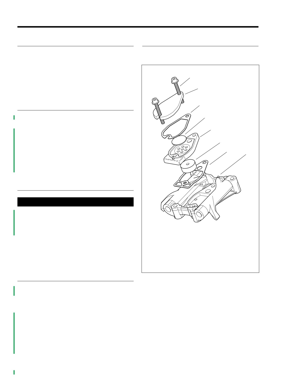
1. See Figure 3-1. Remove two fasteners from breather
assembly.
5
2. Remove breather cover and gasket. Discard cover gas-
ket.
6
3. Remove the breather baffle and gasket. Discard gasket.
4. Pull filter element from bore on inboard side of breather
7
8
baffle. Discard filter element.
5. Pull stem of umbrella valve from hole at top of breather
baffle. Discard umbrella valve.
CLEANING AND INSPECTION
1WARNING
Compressed air can pierce the skin and flying debris
from compressed air could cause serious eye injury.
Wear safety glasses when working with compressed air.
Never use your hand to check for air leaks or to deter-
1.
Fastener
mine air flow rates. (00061a)
2.
Breather cover
3.
Cover gasket
1.
Clean all parts in a non-volatile cleaning solution or sol-
4.
Umbrella valve
vent.
5.
Breather baffle
2.
Thoroughly dry all parts with low pressure compressed
6.
Filter element
air.
7.
Breather baffle gasket
8.
Rocker arm support plate
ASSEMBLY
Figure 3-1. Breather Components
1. See Figure
3-1. Insert stem of new umbrella valve
through center hole at top of breather baffle. Use dena-
tured alcohol or glass cleaner to lubricate stem. Care-
fully pull rubber bead on stem through hole in baffle.
Verify that rubber bead is pulled completely through hole
and resides on bottom side of baffle.
2. Press new filter element into bore at bottom of baffle
Hole in filter element accommodates umbrella valve
stem.
3. Place breather baffle gasket on a clean flat surface.
Aligning holes, place breather baffle, cover gasket and
breather cover on top. Slide two screws through stackup
to keep assembly together until time of installation.
3-6
2004 FLHTCSE: Engine
HOME
ROCKER HOUSING
3.6
VALVE SPRING TO ROCKER HOUS-
f1576x3x
ING CLEARANCE
1
1. After torquing cylinder head bolts, continue top end over-
haul by installing the rocker housings. See ASSEMBLY
under TOP END OVERHAUL in the Touring Models Ser-
vice Manual.
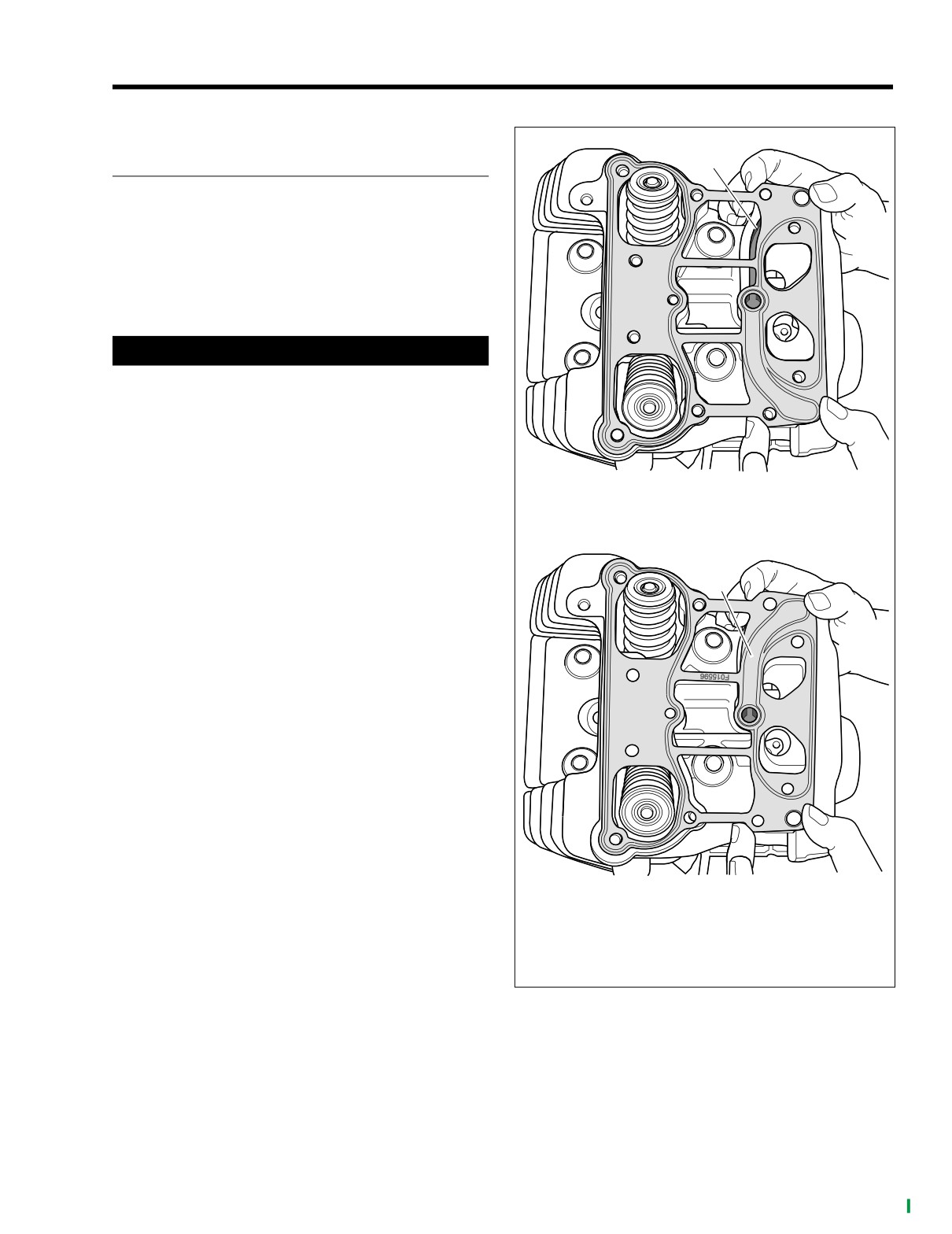
2. Install a new rocker housing gasket on the cylinder head
flange.
CAUTION
Even though all bolt holes (rocker housing, rocker arm
support plate and breather assembly) may appear to be
in alignment, the rocker housing gasket may be installed
upside down. An upside down gasket will result in an
open breather channel causing an oil leak when the vehi-
cle is started, possibly resulting in engine and/or prop-
erty damage.
WRONG
3. See Figure 3-2. Verify that the rocker housing gasket is
installed correctly by noting that the breather channel is
f157x3x
concealed.
2
4. With the indent facing forward, place the rocker housing
into position aligning the holes in the housing with those
in the gasket.
RIGHT
1. Breather channel exposed (wrong)
2. Breather channel concealed (right)
Figure 3-2. Rocker Housing Gasket
2004 FLHTCSE: Engine
3-7
HOME
5. Apply a small dab of LOCTITE THREADLOCKER 243
(blue) (HD-99642-97) to threads of six rocker housing
f1578x3x
bolts.
2
3
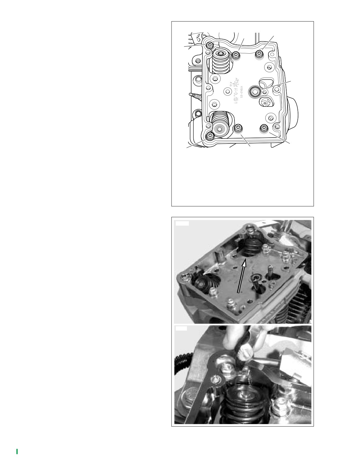
6. See Figure 3-3. Start the rocker housing bolts, two long
1
bolts on the left side of the engine, four intermediate
bolts in the interior.
NOTE
4
Rocker housing and rocker cover bolts have both an internal
and external hex, which allows the bolts to be installed with
either a short 3/16 inch allen wrench (tight spaces), or a 7/16
inch socket or open end/box wrench (open spaces). If the
engine is left in the chassis for service, the short 3/16 inch
allen wrench is indispensable when installing the rocker
housing and rocker cover bolts on the left side of the engine
f1578x3x
(particularly the rear) where there is close proximity to the
frame.
5
7. From the cam cover side, press rocker cover diagonally
6
7
toward the intake valve.
1. Long bolt 1-3/4 in.
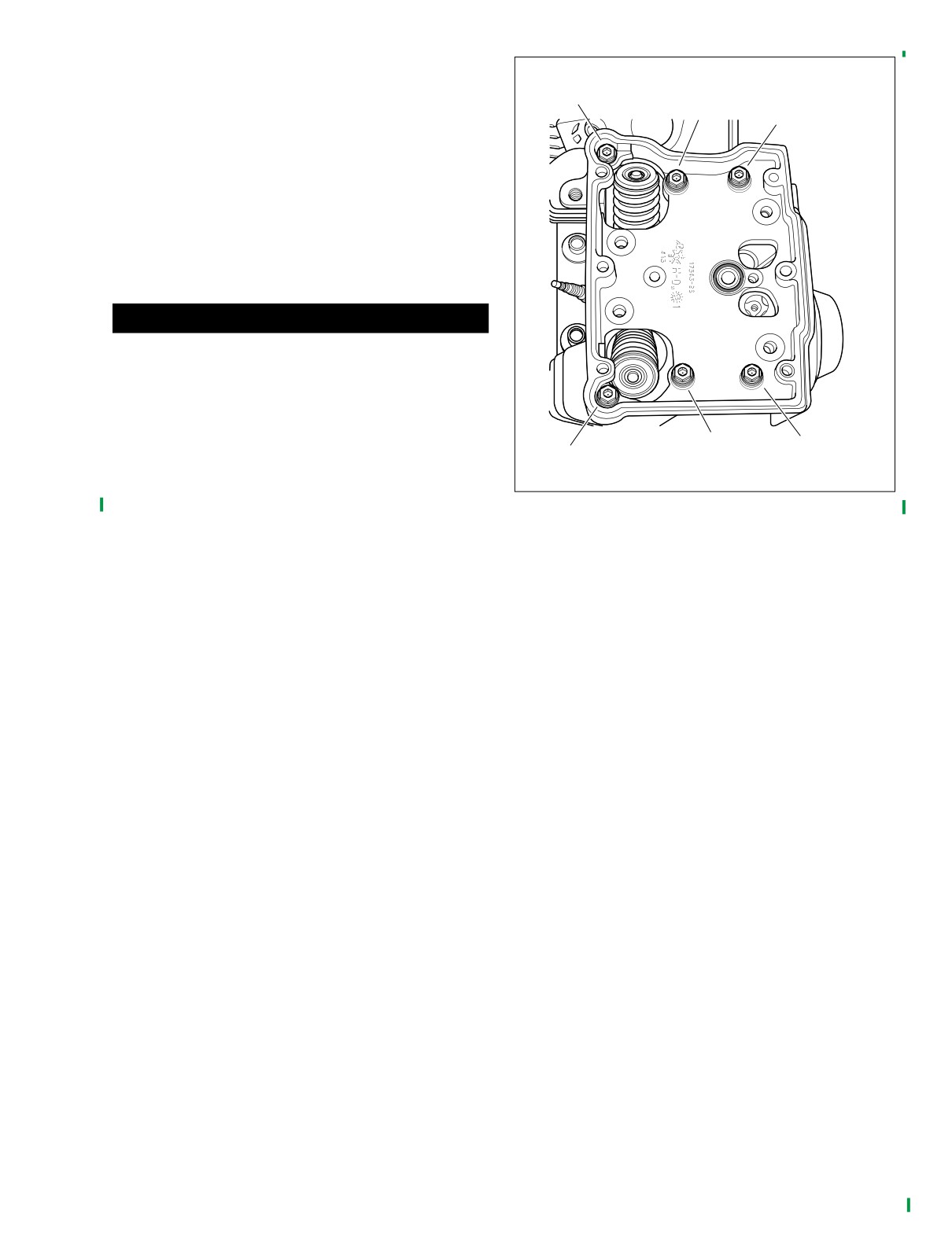
8. See Figure 3-5. Snug bolts in torque sequence to hold
2. Intermediate bolt 1-1/4 in.
housing in position. Do not torque.
3. Intermediate bolt 1-1/4 in.
4. O-ring
9. See Figure 3-4. Using a feeler gauge, check for clear-
5. Intermediate bolt 1-1/4 in.
ance around both valve spring assemblies and the
6. Intermediate bolt 1-1/4 in.
rocker housing.
7. Long bolt 1-3/4 in.
10. If spring assembly contacts rocker housing at any point
Figure 3-3. Rocker Housing Bolt Lengths
around springs, loosen rocker cover bolts and press on
9977
side of cover opposite contact point to produced notice-
able clearance between housing and valve assembly.
8877
Figure 3-4. Valve Spring to Rocker Housing Clearance
3-8
2004 FLHTCSE: Engine
HOME
11. Tighten rocker housing bolts to 120-168 in-lbs (13.6-
f1578x3x
18.9 Nm) in the pattern shown in Figure 3-5.
3
5
NOTE
1
If the engine was left in the chassis for service, final tighten
the rear left rocker housing bolt (rear cylinder) using a torque
wrench with a 1/4 inch drive. Since this tool may not be avail-
able in foot-pounds, tighten the bolt to 120-168 in-lbs.
12. Re-check clearance at both valve spring assemblies and
repeat until there is sufficient clearance between spring
assemblies and rocker housing with the bolts torqued.
CAUTION
O-rings that are missing, distorted, pinched or otherwise
damaged will result in either oil leakage or low oil pres-
sure. Use of the wrong o-ring will have the same results.
Since many o-rings are similar in size and appearance,
always use new o-rings keeping them packaged until use
to avoid confusion.
6
4
2
13. Install new o-ring in groove around breather baffle hole
in rocker housing. Apply a thin film of clean SYN3 engine
Figure 3-5. Rocker Housing Torque Sequence
oil to o-ring before installation.
14. Continue the top end overhaul by installing the hydraulic
lifters in the crankcase bores. See ASSEMBLY under
TOP END OVERHAUL in the Touring Models Service
Manual.
2004 FLHTCSE: Engine
3-9
HOME
CYLINDER HEADS
3.7
GENERAL
Major components of the FLHTCSE engine differ from other
touring models in specification and appearance. However,
service procedures for the following components are the
same as those found in the Touring Models Service Manual.
See CYLINDER HEAD under SUBASSEMBLY SERVICE
AND REPAIR in the Touring Models Service Manual.
For service wear limits, refer to Table 3-17.
9975
2
1
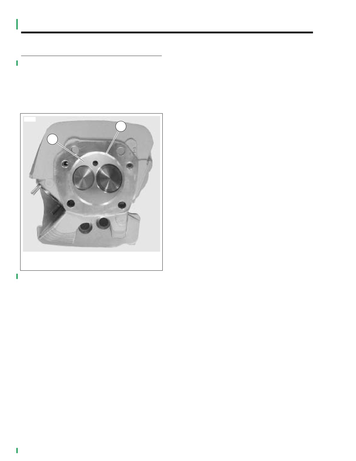
1. Hemispherical combustion chamber
2. Machined relief
Figure 3-6. FLHTCSE Front Cylinder Head
3-10
2004 FLHTCSE: Engine
HOME
PISTONS
3.8
GENERAL
f2113x4x
Major components of the FLHTCSE engine differ from other
touring models in specification and appearance. However,
service procedures for the following components are the
same as those found in the Touring Models Service Manual.
See PISTON on SUBASSEMBLY SERVICE AND REPAIR in
the Touring Models Service Manual.
For service wear limits, refer to Table 3-20. and Table 3-19.
NOTE
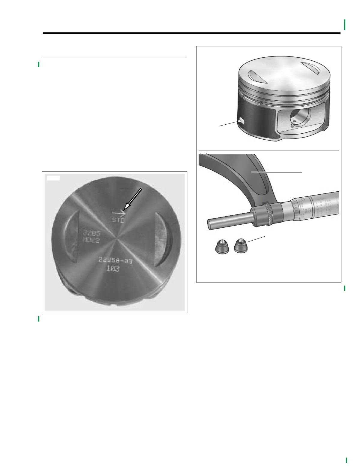
The piston is measured on the bare aluminum to avoid mea-
suring errors. An oval-shaped spot is present on each side of
1
the piston for proper placement of the micrometer. See upper
frame of Figure 3-8. Since the oval openings are too small for
a standard flat anvil micrometer, which would result in mea-
suring errors, use a 4-5 inch micrometer with spherical ball
f2109x3x
anvil adapters. See lower frame of Figure 3-8.
2
9974
3
1.
Oval opening
2.
4-5 inch micrometer
3.
Spherical ball anvil adapters
Figure 3-8. FLHTCSE Piston Measurement
Figure 3-7. FLHTCSE Piston Orientation Arrow
(arrow points to front of engine)
2004 FLHTCSE: Engine
3-11

HOME
BORING AND HONING CYLINDERS
3.9
5. Thoroughly wash the cylinder bore with liquid dish soap
CYLINDER BORE FINISHED SIZE
and warm water to remove all abrasive particles and
residual girt. Continue cleaning until a clean cloth shows
1. For cylinder removal, cleaning, inspection, boring and
no evidence or dirt or debris.
honing and installation, see CYLINDER in the Touring
Models Service Manual.
6. Immediately apply a thin film of clean engine oil to a
2.
Refer to Table 3-24. Bore the cylinder to 0.003 in. (0.08
clean white paper towel and thoroughly wipe the inside
of the cylinder. This prevents the cylinder bore from rust-
mm) under the desired finished size. See BORING and
HONING CYLINDER in the Touring Models Service
ing.
Manual. Refer to Table 3-24.
NOTE
After wiping the cylinder with a clean, oiled paper towel, the
CAUTION
towel will be dark with contamination. Repeat this process
using a new lightly oiled paper towel each time until the towel
An improper crosshatch pattern or too fine a hone will
remains white. The cylinder is now clean.
result in insufficient oil retention and possible piston
seizure and/or high oil consumption.
7. With the cylinder at room temperature, check the piston
3.
Hone the cylinder to its finished size using a 280 grit
clearance in the cylinder in which the piston will run. See
rigid hone followed by a 240 grit flexible ball hone. Hon-
INSPECTION under PISTON in Touring Models Service
ing must be done with the torque plates attached. All
Manual.
honing must be done from the bottom (crankcase end of
8. For cylinder installation, see CYLINDER in Touring Mod-
the cylinder. Work for a 60˚ crosshatch pattern.
els Service Manual.
4.
Stop frequently to examine the cylinder bore and/or take
measurements. Remember, a precise 60˚ cross hatch
pattern in the piston travel area is important.
Table 3-24. Oversize Pistons/Cylinder Bores
PISTON
CYLINDER BORE FINISHED SIZE
TYPE
SIZE
MINIMUM
MAXIMUM
Standard
STD
3.8750 in. (98.4250 mm)
3.8755 in. (98.438 mm)
0.005 in. (0.13 mm)
3.8800 in. (98.552 mm)
3.8805 in. (98.565 mm)
Oversize
0.010 (0.25 mm)
3.8850 in. (98.679 mm)
3.8855 in. (98.692 mm)
3-12
2004 FLHTCSE: Engine
HOME
CAMS AND TIMING MARKS
3.10
GENERAL
Major components of the FLHTCSE engine differ from other
touring models in specification and appearance. However,
service procedures for the following components are the
same as those found in the Touring Models Service Manual.
See Camshafts and Camshaft Bearings under CAM SUP-
PORT PLATE under SUBASSEMBLY SERVICE AND
REPAIR in the Touring Models Service Manual.
f1607a3x
2
1
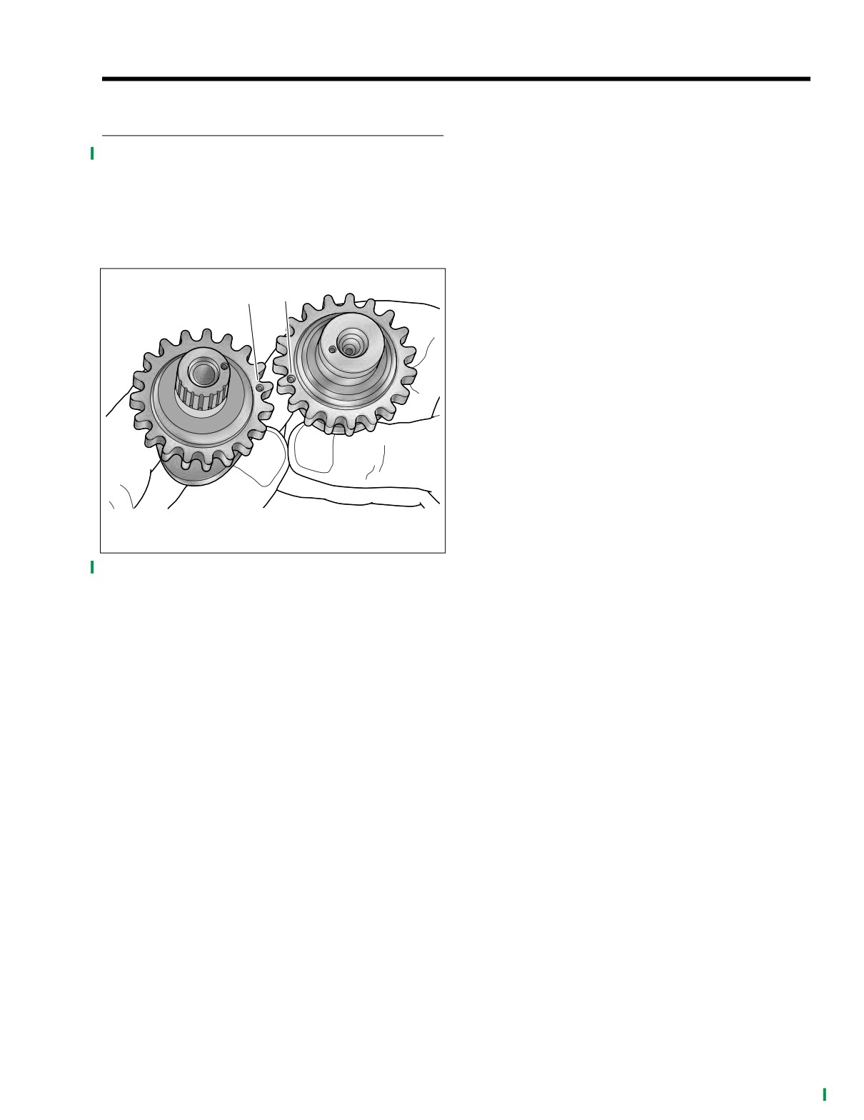
1. Rear camshaft punch mark
2. Front camshaft punch mark
Figure 3-9. FLHTCSE Cam Timing Marks
2004 FLHTCSE: Engine
3-13
HOME
FLYWHEEL/CONNECTING ROD ASSEMBLY
3.11
GENERAL
SPROCKET SHAFT BEARING
INNER RACE REPLACEMENT
For removal, inspection, and installation, see FLYWHEEL/
CONNECTING ROD ASSEMBLY under SUBASSEMBLY
SERVICE AND REPAIR in the Touring Models Service Man-
PART NO.
SPECIALTY TOOL
ual.
For service wear limits, refer to Table 3-21. and Table 3-22.
HD-44358
Flywheel support fixture
NOTE
HD-95637-46A
Wedge attachment
If the flywheel or connecting rods need to be replaced, then
they must be replaced together as one assembly.
Mainshaft bearing inner race
HD-34902B
puller/installer
9978
HD-25070
Robinair heat gun
1. If reusing flywheel, remove bearing inner race and thrust
washer as follows:
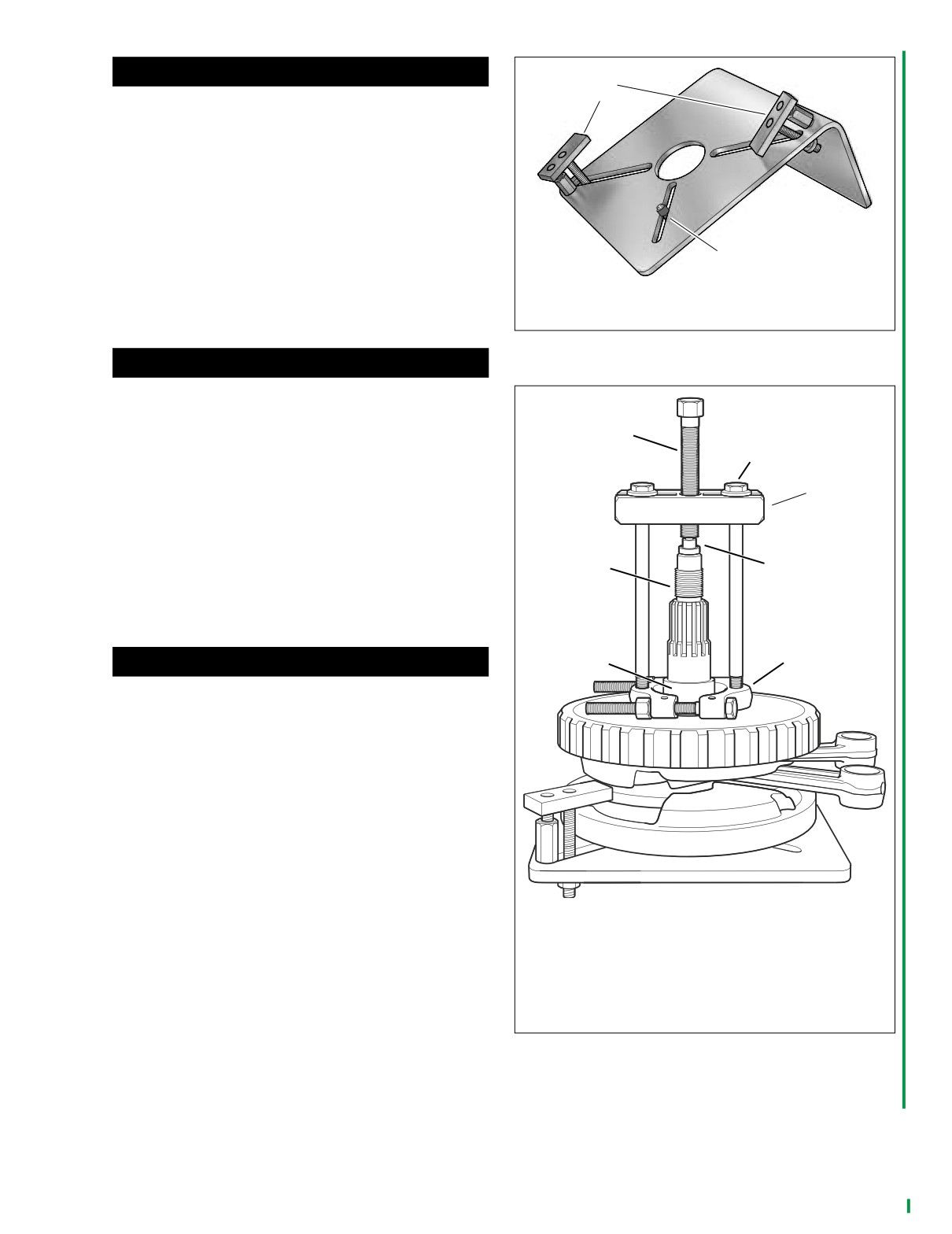
a. Obtain FLYWHEEL SUPPORT FIXTURE
(HD-
44358). See Figure 3-11. Install brass jaws or shop
towels around teeth of vise to prevent damage to
tool. Clamp tool in vise with the round hole topside.
b. Insert crankshaft end through hole resting flywheel
assembly on fixture. Slide knurled locating pin down
slot in tool to engage crank pin hole. Hand tighten
locating pin.
c. Slide hold-down clamp down slot to engage inboard
side of right flywheel half, and then hand tighten
knurled nut at bottom to secure. Repeat step to
secure hold-down clamp on opposite side of fly-
wheel.
NOTE
For proper clamping force, hold-down clamp must not be
tilted. Rotate hex on outboard stud until clamp is level.
d. Position WEDGE ATTACHMENT (HD-95637-46A)
on inboard side of thrust washer and turn hex nuts
an equal number of turns to draw halves of wedge
together.
CAUTION
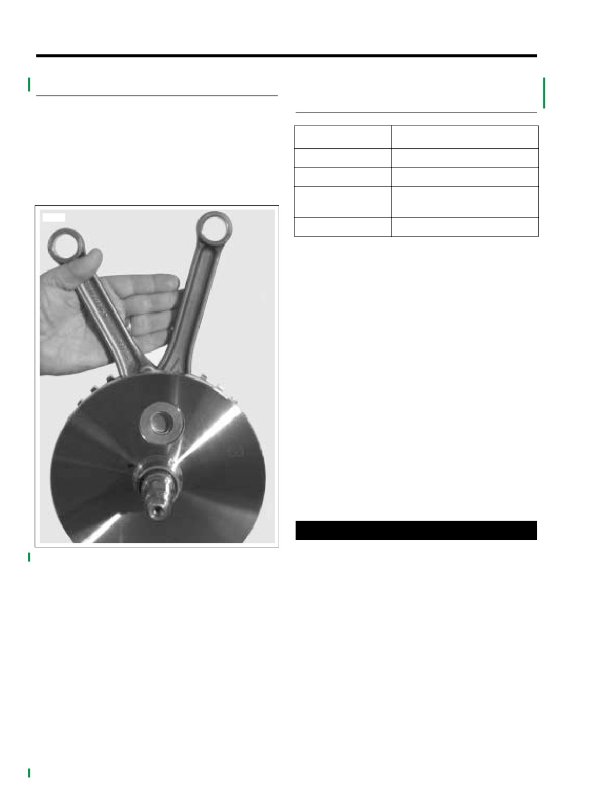
Install wedge attachment only so far as necessary to
Figure 3-10. FLHTCSE
ensure positive contact with thrust washer. Installing
Flywheel/Connecting Rod Assembly
tool with more contact than absolutely necessary will
result in damage to flywheel.
e. Obtain two 3/8-16 inch bolts 6-1/2 inches long (with
flat washers). Install flat washers on bolts. Obtain
bridge, forcing screw and hardened plug from
MAINSHAFT BEARING INNER RACE PULLER/
INSTALLER (HD-34902B).
f.
Slide one bolt into channel on each side of bridge
so that flat washer is between bridge and bolt head.
Thread bolts into wedge attachment an equal num-
ber of turns.
g. Sparingly apply graphite lubricant to threads of forc-
ing screw to prolong service life and ensure smooth
operation. Start forcing screw into center hole of
bridge.
3-14
2004 FLHTCSE: Engine
HOME
CAUTION
f1869x3d
1
Failure to use hardened plug may result in damage to
forcing screw and/or sprocket shaft.
h. Place cupped side of hardened plug against end of
sprocket shaft. Thread forcing screw into bridge until
the steel ball at the end of the screw makes firm
contact with hardened plug.
i.
Using the ROBINAIR HEAT GUN (HD-25070), uni-
formly heat the bearing inner race for about 30 sec-
onds using a circular motion.
2
NOTE
1.
Hold-down clamp
To facilitate removal without heat, apply a light penetrating oil
2.
Locating pin
to shaft and leading edge of bearing inner race.
Figure 3-11. Flywheel Support Fixture (Part No. HD-
44358)
1WARNING
Never use both heat and penetrating oil. Use only one or
f2154x3x
the other. Excessive heat can cause the penetrating oil
to ignite resulting in flames or fire. Inadequate safety
1
precautions can result in death or serious injury.
2
j.
Turn forcing screw until thrust washer and bearing
inner race move approximately 1/8 inch (3.2 mm).
3
k. Turn hex nuts an equal number of turns to separate
halves of WEDGE ATTACHMENT.
l.
After bottoming thrust washer on shaft, reposition
WEDGE ATTACHMENT
(HD-95637-46A) on
7
4
inboard side of bearing inner race. Turn hex nuts an
equal number of turns to draw halves of wedge
together.
6
5
CAUTION
Install wedge attachment only so far as necessary to
ensure positive contact with bearing inner race. Install-
ing tool with more contact than absolutely necessary
will result in damage to flywheel.
m. Verify that the tool assembly is square, so that the
bearing inner race is not cocked during removal.
See Figure 3-12.
n. Using the ROBINAIR HEAT GUN (HD-25070), uni-
formly heat the bearing inner race for about 30 sec-
onds using a circular motion.
NOTE
1.
Forcing screw
To facilitate removal without heat, apply a light penetrating oil
2.
3/8-16 Inch bolt with flat washer
to shaft and leading edge of bearing inner race.
3.
Bridge
o. Turn forcing screw until bearing inner race is pulled
4.
Hardened plug
free of sprocket shaft.
5.
Wedge attachment
p. Remove thrust washer from sprocket shaft.
6.
Bearing inner race
7.
Sprocket shaft
q. Discard thrust washer and bearing inner race.
Figure 3-12. Remove Inner Race From Sprocket Shaft
2. Place new thrust washer over sprocket shaft with the ink
stamp facing outside
(and the chamfer on the ID
inboard).
2004 FLHTCSE: Engine
3-15
HOME
3. Place new bearing inner race on bench top. Using the
ROBINAIR HEAT GUN (HD-25070), uniformly heat
h9772-55b
bearing inner race for about 60 seconds using a circular
motion.
4.
Wearing suitable gloves to protect hands from burns,
place heated bearing inner race over sprocket shaft.
NOTE
To facilitate installation without heat, apply a light penetrating
oil to shaft and leading edge of bearing inner race.
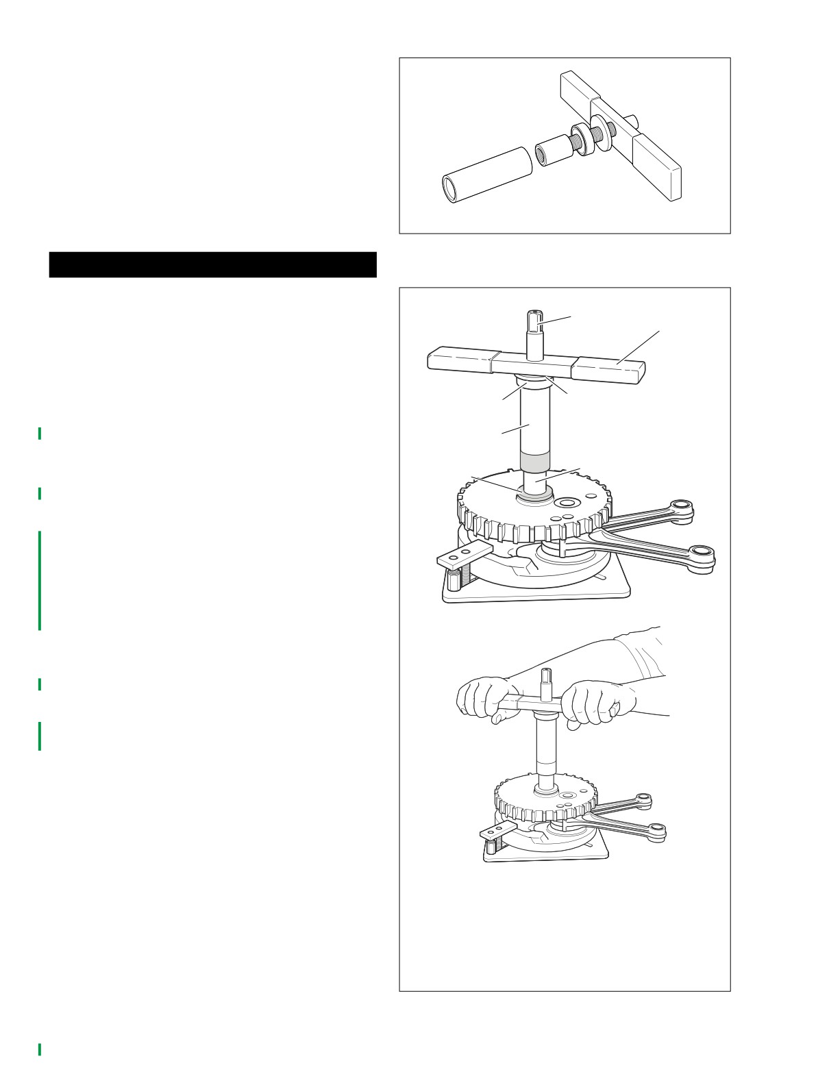
Figure 3-13. Sprocket Shaft Timken Bearing
Cone Installer (Part No. HD-97225-55B)
1WARNING
Never use both heat and penetrating oil. Use only one or
f2152x3x
the other. Excessive heat can cause the penetrating oil
1
to ignite resulting in flames or fire. Inadequate safety
2
precautions can result in death or serious injury.
5.
See Figure
3-13. Obtain the SPROCKET SHAFT
TIMKEN BEARING CONE INSTALLER (HD-97225-
3
55B). Assemble tool as described below.
4
a. See Figure 3-14. Thread pilot shaft onto sprocket
5
shaft until contact is made with shoulder.
6
b. Sparingly apply graphite lubricant to threads of pilot
7
shaft to prolong service life and ensure smooth
operation.
c. Slide sleeve over pilot until it contacts bearing inner
race.
d. Slide Nice bearing and large flat washer over pilot
until contact is made with sleeve.
e. Thread handle onto pilot shaft. See upper frame of
f2153x3x
Figure 3-14.
6.
Rotate handle of tool in a clockwise direction until bear-
ing inner race bottoms against thrust washer. See lower
frame of Figure 3-14.
7.
Remove handle, flat washer, Nice bearing, sleeve and
pilot from sprocket shaft.
1.
Pilot shaft
2.
Handle
3.
Flat washer
4.
Nice bearing
5.
Sleeve
6.
Inner race
7.
Thrust washer
Figure 3-14. Press Inner Race Onto Sprocket Shaft
3-16
2004 FLHTCSE: Engine
HOME
OIL VENT LINE
3.12
REPLACEMENT
9968
5
2
PART NO.
SPECIALTY TOOL
3
4
1
HD-41137
Hose clamp pliers
IMPORTANT NOTE
Dispose of oil in accordance with local regulations.
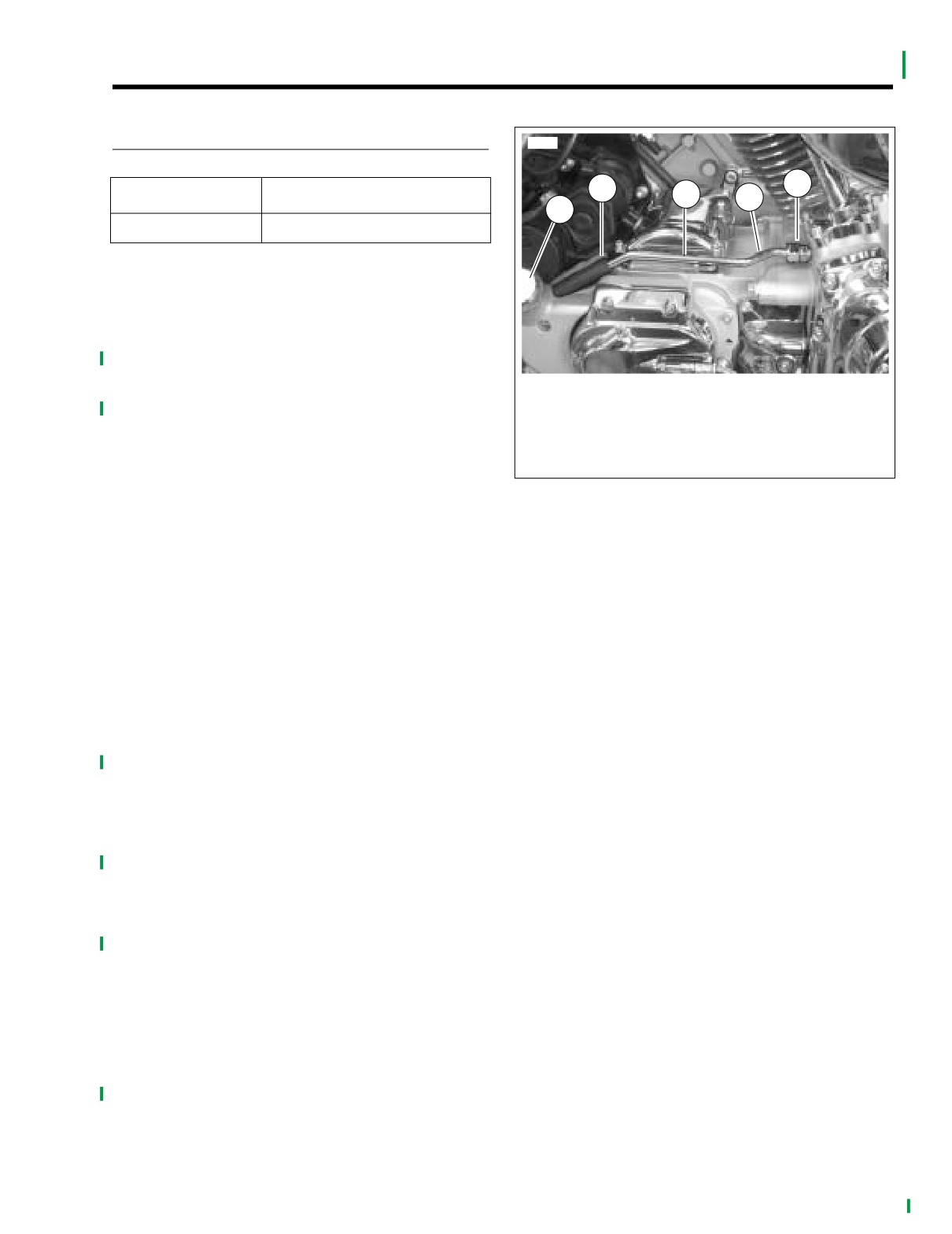
1. See Figure 3-15. Back the chrome nut off of the crank-
case oil fitting.
2. Using side cutters, cut the clamps on the short length of
1.
Oil spout fitting
hose at the oil spout end of the vent line.
2.
Hose
3.
Oil vent line parallel to transmission cover
3. Remove the oil vent line.
4.
S-bend
5.
Crankcase fitting nut
4. If necessary, remove both fittings and clean sealant from
threads in crankcase and oil fill.
Figure 3-15. Oil Vent Line (clamps removed)
NOTE
The spout fitting is a nipple styled fitting.
5.
If removed, identify the crankcase end fitting and using
pipe sealant or TEFLON® tape, prepare the tapered
threaded end of fitting. Thread fitting into crankcase and
tighten to 130-150 in-lbs (14.7-16.9 Nm).
6.
If removed, identify oil spout fitting and using pipe seal-
ant or TEFLON® tape, prepare the tapered threaded end
of fitting. Thread fitting into oil spout and tighten to 130-
150 in-lbs (14.7-16.9 Nm).
7.
Slide crankcase fitting nut and rubber ferrule on crank-
case end of vent line.
8.
Push new hose with new clamps on the oil spout end of
chrome vent line.
9.
Orient s-bend in vent line toward crankcase and slide
chrome vent line into case fitting.
10.
Push hose onto oil spout fitting.
11.
Position line parallel with transmission cover and with
clearance to other components.
12.
Push rubber ferrule into crankcase fitting. Thread
chrome nut over ferrule and hand tighten.
13.
Tighten chrome nut to 60-80 in-lbs (6.8-9.0 Nm).
14.
Using HOSE CLAMP PLIERS (HD-41137), crimp the
clamps on the hose.
15.
Operate motorcycle and inspect for leaks.
2004 FLHTCSE: Engine
3-17
HOME
OIL COOLER OPERATION
3.13
GENERAL
8871
1
For engine oil flow through the engine, See ENGINE OIL
FLOW under GENERAL INFORMATION in Touring Models
2
3
Service Manual.
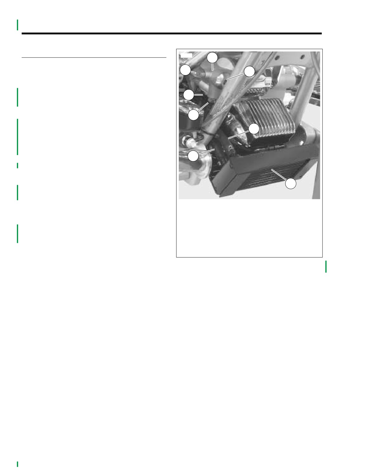
See Figure 3-16. The FLHTCSE is equipped with a factory
installed oil cooler controlled by a thermostat in the oil filter
4
mount.
Engine oil flows from the crankcase through the oil filter
5
mount to the oil cooler through a supply hose. The oil circu-
lates through the finned tubes of the cooler to dissipate heat
6
and returns to the oil filter mount through a return hose.
Under pressure from the crankcase, engine oil enters the
lower port in the oil filter mount. A passage way directs oil to
7
flow to the oil filter. The oil circulates through the oil filter ele-
ment and out the oil filter threaded fitting.
From the oil filter, the filtered oil flows in two directions:
8
1. From the oil filter adapter Into the thermostat chamber.
2. Through a side passage and out the supply oil fitting to
the oil cooler.
1.
Oil filter mount
2.
Transfer passage cover
See Figure 3-18.The thermostat chamber is located in line
3.
Thermostat plug
with the return port to the engine crankcase. The thermostat
4.
Oil return fitting
assembly consists of a temperature sensitive plunger com-
5.
Oil supply fitting
pressed between a spring-loaded piston, spring and an open
6.
Supply hose
cage spreader.
7.
Return hose
While the engine oil temperature is below 180˚ F (82˚ C), the
8.
Oil cooler
thermostat is in its closed position. See Closed Thermostat
under 3.13 OIL COOLER OPERATION.
Figure 3-16. Oil Cooler and Bracket
(chrome cover removed for photo clarity)
The filtered oil is circulated through the transfer passage
where it returns to the crankcase. At the same time, oil is
supplied under pressure to the oil cooler even though the oil
cooler return port is blocked.
While the engine operates at average temperatures, approxi-
mately 195˚ F (91˚ C), the thermostat partially opens allowing
cooler oil from the cooler to mix with warmer oil from the oil
transfer passage as the oil returns to the crankcase. See Par-
tially Open Thermostat under 3.13 OIL COOLER OPERA-
TION.
When the engine oil exceeds 210˚ F (99˚ C), the thermostat
is in its fully open position. See Fully Open Thermostat under
under 3.13 OIL COOLER OPERATION.
In this position, all the oil flows through the oil cooler and
back through the oil filter mount before returning to the crank-
case.
NOTE
Regardless of whether the thermostat is closed, partially
open or fully open, oil is always pressurized in the transfer
passage, the oil cooler supply hose, the oil cooler and the oil
return hose.
The oil cooler should always be checked for dirt and debris to
maintain cooler efficiency at every service interval.
3-18
2004 FLHTCSE: Engine
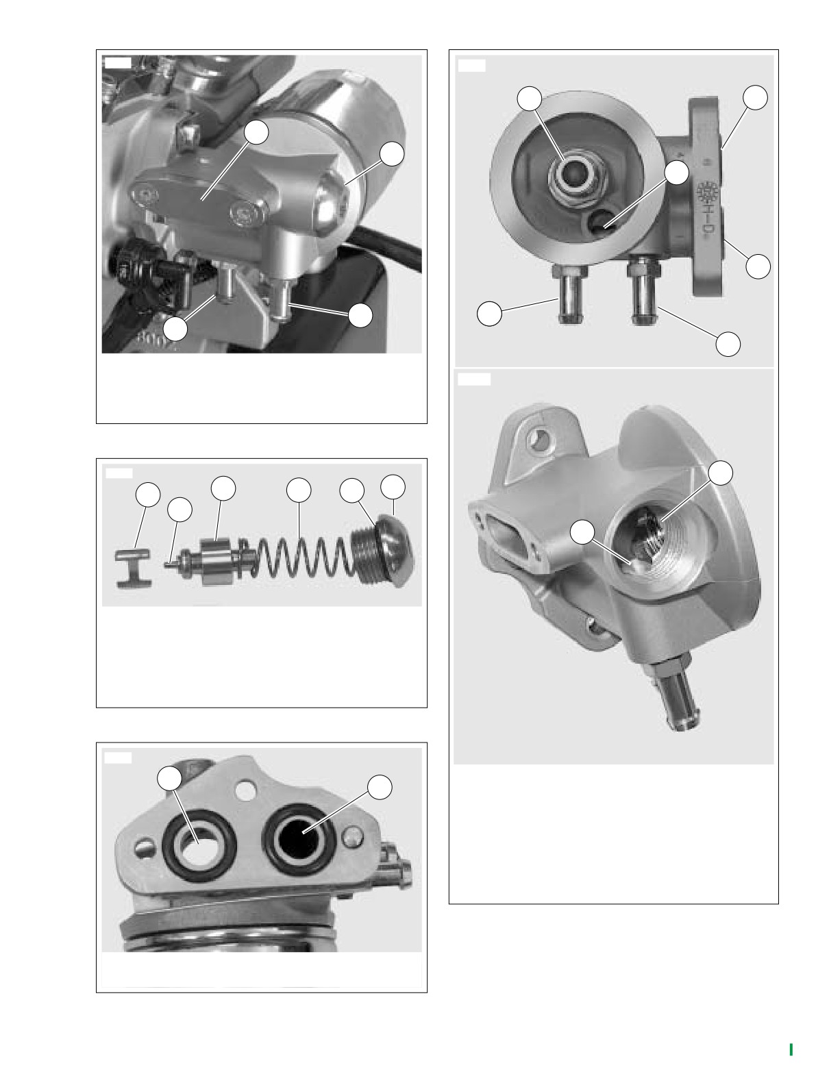
HOME
9980
8872
1
3
1
2
2
4
4
6
3
5
1.
Transfer passage cover
2.
Thermostat plug
8875
3.
Return hose fitting
4.
Supply hose fitting
Figure 3-17. Oil Filter Mount on Engine
9982
7
3
6
4
5
1
2
8
1. Open cage spreader
2. Thermostat plunger
3. Piston
4. Spring
5. O-ring
6. Thermostat plug
Figure 3-18. Thermostat Assembly
9931
1
1.
Oil filter adapter
2
2.
Passage to oil filter element
3.
Return to crankcase
4.
Supply from crankcase
5.
Return hose fitting
6.
Supply hose fitting
7.
Open passage from oil filter
8.
Open passage to oil cooler supply
Figure 3-20. Oil Filter Mount
1. Return port to crankcase (thermostat removed)
2. Supply port from crankcase
Figure 3-19. Oil Filter Mount Ports to Crankcase
2004 FLHTCSE: Engine
3-19
HOME
Closed Thermostat
8876
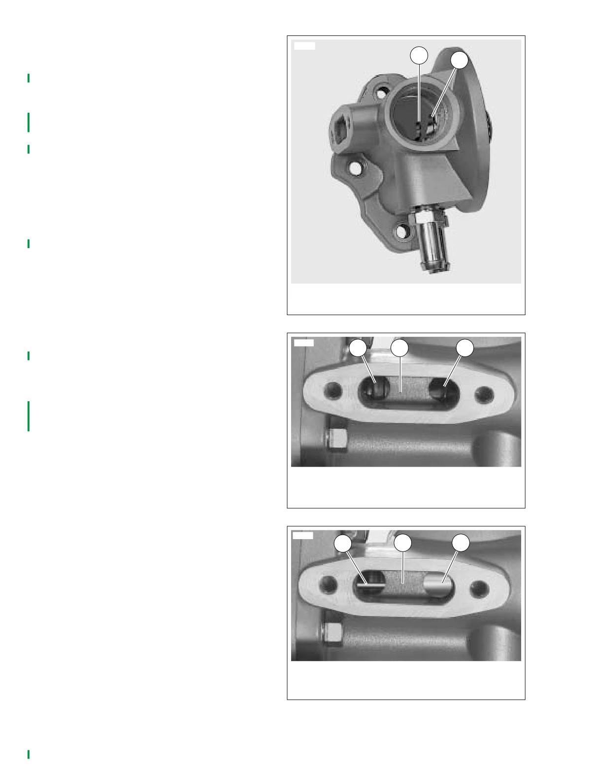
See Figure 3-21. While the engine oil is cool, the thermostat
1
2
is in its closed position. The spring holds the piston over the
return passage from the oil cooler. Even though oil pressure
is supplied to the oil cooler, oil is blocked from returning from
the oil cooler.
See Figure 3-22. When closed, the piston opens a port in the
transfer passage along the side of the thermostat chamber.
The filtered oil is circulated around the piston through the
transfer passage and into a port in the thermostat chamber
where it flows through the open cage spreader and returns to
the crankcase.
Partially Open Thermostat
As the engine oil exceeds 180˚ F (82˚ C), the thermostat
plunger begins to expand and compresses the spring push-
ing against the piston. The piston partially opens the return
passage from the oil cooler and partially closes the port from
the chamber to the transfer passage.
While the engine operates at an average temperature, 195˚ F
(91˚ C), the thermostat remains partially open allowing cooler
oil from the cooler to mix with warmer oil from the oil filter.
1. Return passage from oil cooler
2. Open passage from oil filter
Fully Open Thermostat
Figure 3-21. Thermostat Chamber
See Figure 3-23. The thermostat fully opens when the engine
oil temperature exceeds 210˚ F (99˚ C). The piston fully
8874
1
2
3
closes the port to the transfer passage and opens the return
passage from the oil cooler.
In this position, all the oil flows from the oil filter through the
oil cooler and back through the return passage before return-
ing to the crankcase. The oil from the oil cooler return will
back up under pressure in the transfer passage even though
the port from the oil filter is closed.
1. Port open from oil filter
2. Oil under pressure
3. Port open to crankcase return
Figure 3-22. Closed Thermostat
8873
1
2
3
1.
Port open to oil cooler return
2.
Oil under pressure
3.
Port closed from oil filter
Figure 3-23. Fully Open Thermostat
3-20
2004 FLHTCSE: Engine
HOME
OIL COOLER
3.14
REMOVAL
INSTALLATION
1. Cover the front fender to protect finish.
PART NO.
SPECIALTY TOOL
IMPORTANT NOTE
Dispose of oil in accordance with local regulations.
HD-41137
Hose clamp pliers
2. Place a container under the motorcycle to catch excess
oil.
1. If replacing the hoses, install new hoses with clamps at
3. Remove the fasteners holding the oil cooler and cover to
the oil filter mount. Using HOSE CLAMP PLIERS (HD-
mounting bracket.
41137), clamp the supply and return hoses at the oil fil-
ter mount.
4. Pull the cooler and cover forward and, using side cutters,
cut the clamps on the supply and return hoses.
2. Apply LOCTITE Thread Sealant to threads of oil pres-
sure switch and install oil pressure switch. Tighten to 96-
5. Remove the oil cooler with cover.
144 in-lbs. (10.84-16.26 Nm).
NOTE
3. Connect oil pressure switch wire lead.
The oil cooler guard is held in place with adhesive tape.
4. Attach hoses to oil cooler. Using HOSE CLAMP PLIERS
6. If replacing the oil hoses, remove oil pressure switch to
(HD-41137), clamp the supply and return hoses at the
gain access to clamps. Cut clamps at oil filter mount.
oil cooler.
Remove oil hoses.
5. Install oil cooler and cover to mounting bracket. Tighten
7. The oil cooler should be checked for dirt and debris.
fasteners to 80-110 in-lbs (9.1-12.4 Nm).
6. Operate motorcycle and inspect for leaks.
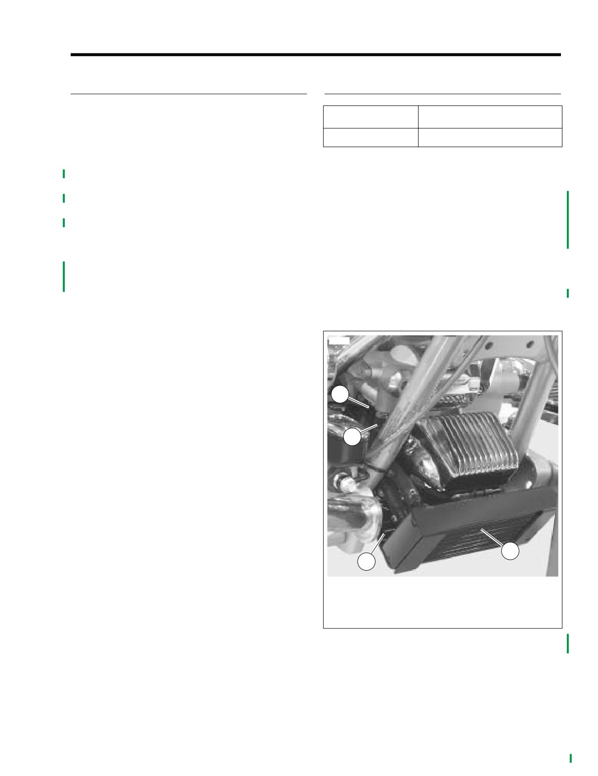
8871
1
2
3
4
1.
Return hose clamp
2.
Supply hose clamp
3.
Oil cooler and guard
4.
Bracket
Figure 3-24. Oil Cooler and Mount
(chrome cover removed for photo clarity)
2004 FLHTCSE: Engine
3-21
HOME
OIL FILTER MOUNT
3.15
REMOVAL
9980
PART NO.
SPECIALTY TOOL
HD-42311 or HD-44067
Oil filter wrench
1. Place a container under motorcycle to catch excess oil.
2. Bend a cardboard funnel and fit to motorcycle to route
fluid away from regulator and oil cooler to container.
3. Using OIL FILTER WRENCH (HD-42311 or HD-44067),
remove oil filter. Discard oil filter
IMPORTANT NOTE
Dispose of oil in accordance with local regulations.
4. If necessary, remove the threaded oil filter adapter and
oil pressure switch.
5. Using side cutters, cut the clamps and remove oil cooler
hoses.
6. If necessary, loosen but do not remove thermostat plug.
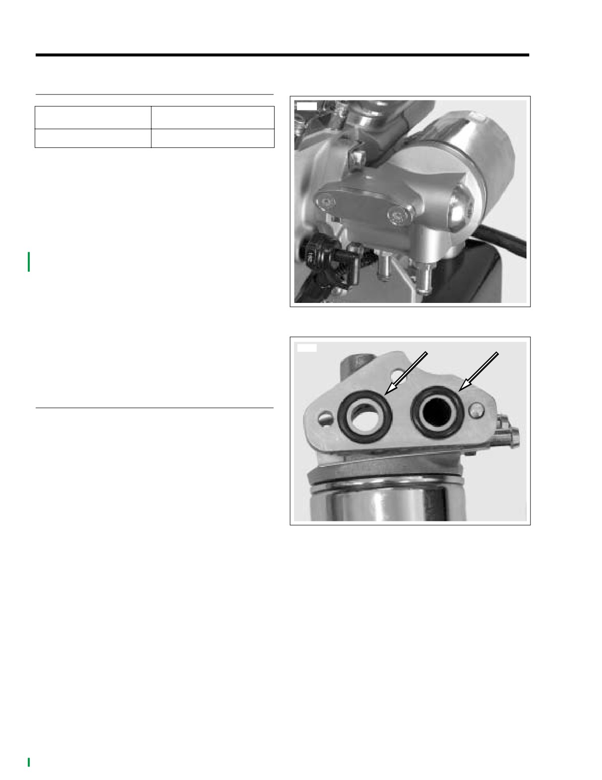
Figure 3-25. Oil Filter Mount (engine removed from frame)
7. Bend tabs of the lockplate away from bolt heads.
8. Remove oil filter mount lockplate fasteners and flat
washers. Discard lockplate.
9931
9.
Remove middle bolt with flat washer and remove oil filter
mount.
DISASSEMBLY
1. If necessary, remove the thermostat. See 3.16 THER-
MOSTAT.
2. See Figure 3-26. Remove the o-rings in the oil filter
mount.
3. Remove the transfer passage cover.
4. Remove the transfer passage cover gasket.
5. Remove the two oil cooler line fittings.
6. Clean the oil passages in a cleaning solution or solvent.
7. Remove thread locking adhesive from the threads of the
oil filter adapter.
Figure 3-26. Oil Filter Mount O-rings
(thermostat removed)
8. Inspect the oil passages and the oil filter mount.
3-22
2004 FLHTCSE: Engine
HOME
ASSEMBLY
CAUTION
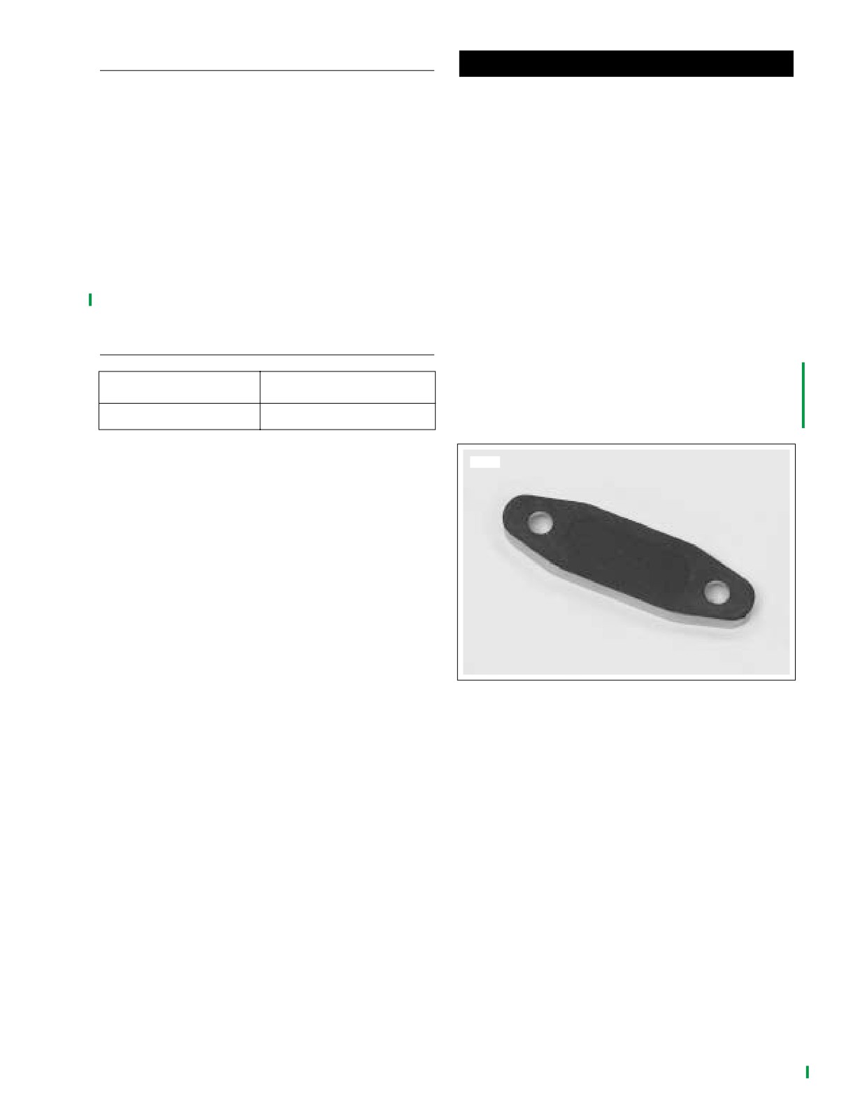
1. See Figure 3-27. Install a new gasket on the transfer
To avoid cross threading tapped holes, exercise care
passage cover.
when starting hex head bolts in crankcase.
2. Install the transfer passage cover. Tighten to 90-120 in-
7. Align holes in filter mount flange with holes in crankcase
lbs (10.2-13.5 Nm).
and tighten bolts until snug.
3. Using pipe sealant or TEFLON tape, prepare the
8. Install flat washer on remaining fastener, apply LOCTITE
tapered threaded end of oil supply and return fittings and
to threads and install in middle hole of mount flange.
install fittings.
9. Starting at the top, alternately tighten the fasteners to
4. If removed, replace the thermostat components:
130-150 in-lbs (14.7-16.9) Nm.
a. Replace the spreader.
10. Bend the ends of the lockplate to capture the top and
b. Replace the thermostat plunger and piston.
bottom fasteners.
c. Replace the spring.
11. If disassembled, tighten the Thermostat plug to 15-20 ft-
d. Install a new o-ring and loosely install thermostat
lbs (20.4-27.1 Nm).
plug.
12. Apply LOCTITE THREADLOCKER 243 (blue) to tapered
threads of oil filter adapter. Install oil filter adapter and
tighten to 12-16 ft-lbs (16.3-21.7 Nm).
INSTALLATION
13. Install a new oil filter. See SCHEDULED MAINTE-
NANCE in Touring Models Service Manual.
PART NO.
SPECIALTY TOOL
NOTE
If removed, install oil pressure switch using LOCTITE Thread
HD-41137
Hose clamp pliers
Sealant and tighten to 96-144 in-lbs (10.84-16.26 Nm).
1. Install the oil cooler oil hoses to the filter mount with new
9983
clamps.
2. Using HOSE CLAMP PLIERS (HD-41137), crimp the
clamps.
3. Place flat washers in recessed bolt holes at top and bot-
tom of filter mount flange.
4. Align holes in lockplate with holes in flat washers.
5. Slide two fasteners through lockplate, flat washers and
filter mount flange. Apply LOCTITE
243 (blue)
(HD-
99642-97) to threads of installed bolts.
6. See Figure 3-26. Install new o-rings into grooves in oil
filter mount.
Figure 3-27. Transfer Passage Cover and Gasket
2004 FLHTCSE: Engine
3-23
HOME
THERMOSTAT
3.16
TEST PROCEDURE
REMOVAL
1.
Using an infrared thermometer, measure the tempera-
1. Allow the motorcycle to cool.
ture at the oil pan and at the oil cooler while operating
2. Place a catch pan under motorcycle.
motorcycle.
3. Bend a cardboard funnel and fit to motorcycle to route
2.
Compare temperatures.
fluid away from regulator and oil cooler to container.
a. If the temperature of the oil cooler follows the tem-
IMPORTANT NOTE
perature of the oil pan at temperatures below 180˚ F
Dispose of oil in accordance with local regulations.
(82˚ C), then the thermostat may be stuck open.
Allow the engine to cool, remove the thermostat.
4. See Figure 3-28. With a ball Allen wrench, loosen and
and proceed.
remove the thermostat plug.
b. If the temperature of the oil cooler is less than that
5. Remove the spring.
of the oil pan below 180˚ F (82˚ C) but, above 180˚
6. Remove the thermostat plunger and piston with a pair of
F (82˚ C), follows the temperature of the oil pan, the
needle nosed pliers.
thermostat is operating correctly.
7. Remove the open cage spreader with a pick.
c. If the oil pan exceeds 210˚ F (99˚ C) and the oil
cooler is cooler, then the thermostat may be stuck
closed. Allow the engine to cool, remove the ther-
INSTALLATION
mostat and proceed.
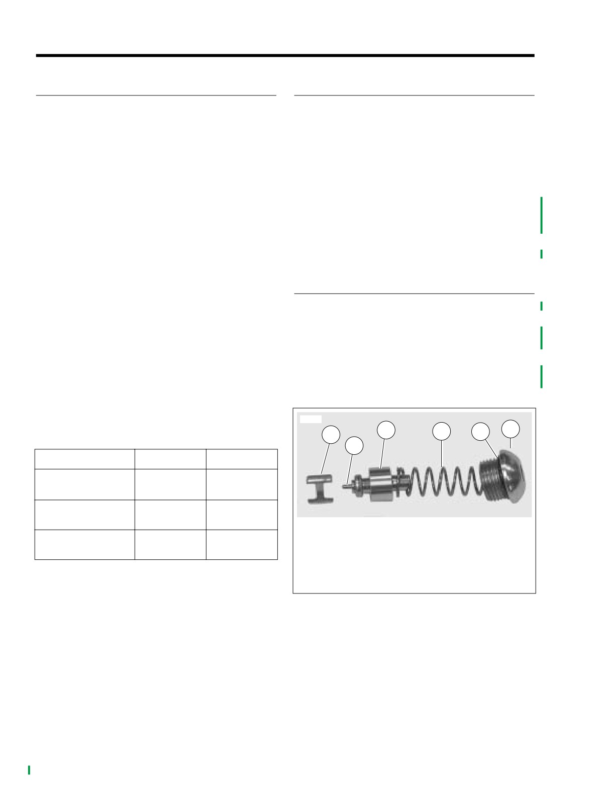
1. See Figure 3-28. Insert the open cage spreader part
3.
Verify that thermostat plunger is fully retracted.
way into thermostat chamber.
4.
Place thermostat plunger in a container of water with a
2. Install the thermostat plunger and piston together.
thermometer.
3. Locate the plunger in the spreader and push in to bottom
5.
Refer to Table 3-25. Heat water to START TO OPEN
of chamber.
temperature. Verify that the plunger extends.
4. Install the spring.
6.
Heat water pass START TO OPEN temperature to FULL
OPEN temperature and verify that plunger is fully
5. Fit a new o-ring and install thermostat plug. Tighten to
extended.
15-20 ft-lbs (20.4-27.1 Nm).
7.
If plunger does not extend per specifications, replace
thermostat assembly.
9982
3
4
5
6
1
Table 3-25. Thermostat Operating Range
2
ITEM
FAHRENHEIT
CELSIUS
START TO OPEN
180˚
82˚
(closed)
AVERAGE
195˚
91˚
(partially open)
1. Open cage spreader
FULL OPEN
2. Thermostat plunger
210˚
99˚
(fully open)
3. Piston
4. Spring
5. O-ring
6. Thermostat plug
Figure 3-28. Thermostat Components
3-24
2004 FLHTCSE: Engine

HOME
SPECIFICATIONS
6.1
Table 6-1. Gear Ratios
Table 6-4. Drive Belt Deflection
GEAR
RATIO
DEFLECTION
IN.
MM
1
10.11
On Jiffy Stand
Without Rider or
2
6.958
1/4-5/16
6.4-7.9
Luggage with 10-
at 10 lbs force
at 4.5 kg force
3
4.953
psi (69 kPa) in
Rear Shocks
4
3.862
5
3.15
Motorcycle
3/16-1/4
4.8-6.4
Upright With rear
at 10 lbs force
at 4.5 kg force
Wheel in Air
Table 6-2. Primary Chain Free Play
Table 6-5. Sprockets
FREE PLAY
IN.
MM
SPROCKET
NUMBER OF TEETH
COLD Engine
5/8-7/8
15.9-22.2
Engine
25
HOT Engine
3/8-5/8
9.5-15.9
Clutch
36
Transmission
32
Rear wheel
70
Table 6-3. Primary Chaincase Lubricant
OZ
ML
Amount
32
946
Part No.
Quart Bottle
99824-03/00QT
2004 FLHTCSE: Drive
6-1