Harley Davidson 2004 Touring Models. Service Manual - page 64
HOME
TORQUE VALUES
6.2
ITEM
TORQUE
NOTES
Clutch inspection cover
84-108 in-lbs
10-12 Nm
page 6-3
6-2
2004 FLHTCSE: Drive
HOME
CLUTCH RELEASE BEARING
6.3
REMOVAL
9992
1WARNING
To prevent accidental vehicle start-up, which could
2
cause death or serious injury, remove maxi-fuse before
1
proceeding. (00251a)
1.
Remove Maxi-Fuse.
2. Remove clutch inspection cover.
3.
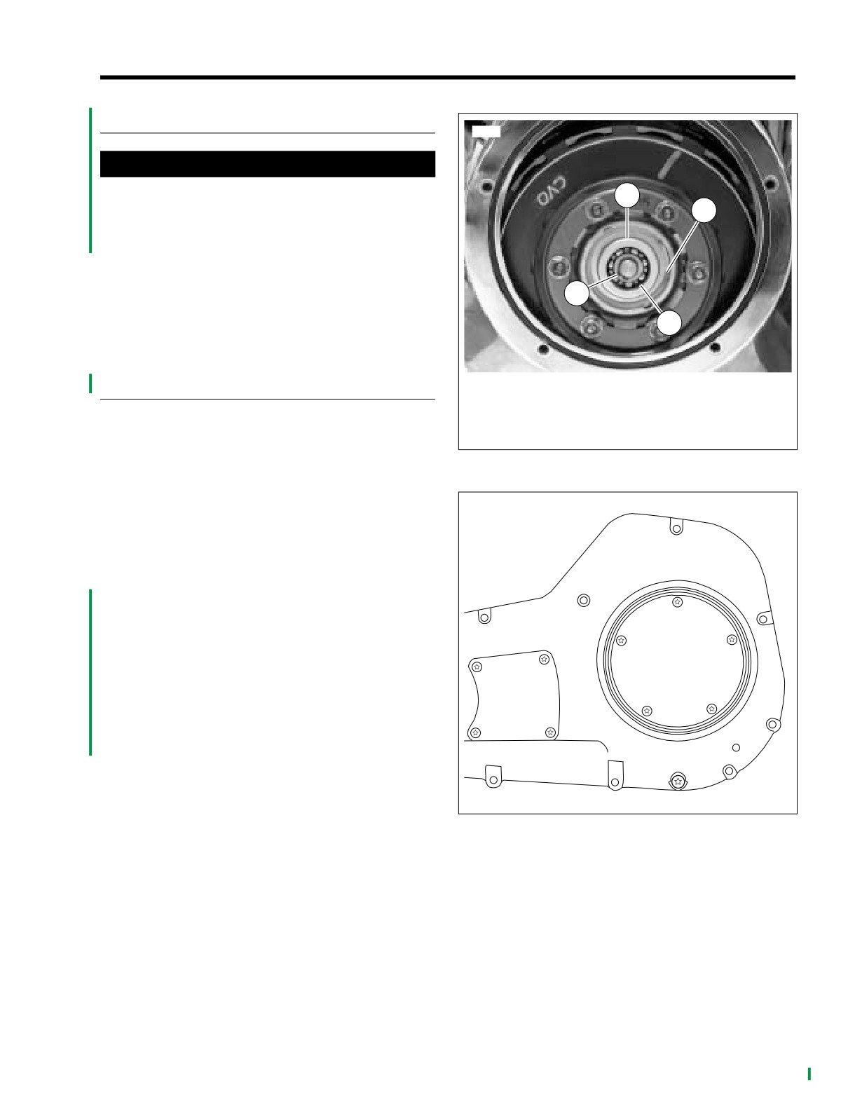
See Figure 6-1. Remove outer retainer clip (1).
3
4.
Pull out release bearing plate (2) with push rod.
5.
Remove push rod retainer (3).
4
6.
Press out bearing (4).
INSTALLATION
1.
Outer retainer clip
2.
Release bearing plate
1. See Figure 6-1. Pressing on the outer race, press a new
3.
Push rod retainer
bearing (4) into plate (2).
4.
Release bearing
2. Assemble push rod to plate (2).
Figure 6-1. Clutch Release Bearing
3. Snap in push rod retainer (3).
4. Slide push rod and clutch release bearing through clutch
pack to secondary clutch actuator.
f1209a6x
5. Snap in outer retainer (1).
6. See Figure
6-2. Install clutch inspection cover. In
sequence, tighten fasteners to
84-108 in-lbs
(10-12
Nm).
7.
Install Maxi-Fuse.
1
3
4
2
5
Figure 6-2. Clutch Inspection Cover Torque Sequence
2004 FLHTCSE: Drive
6-3
HOME
NOTES
6-4
2004 FLHTCSE: Drive
HOME
SPECIFICATIONS
7.1
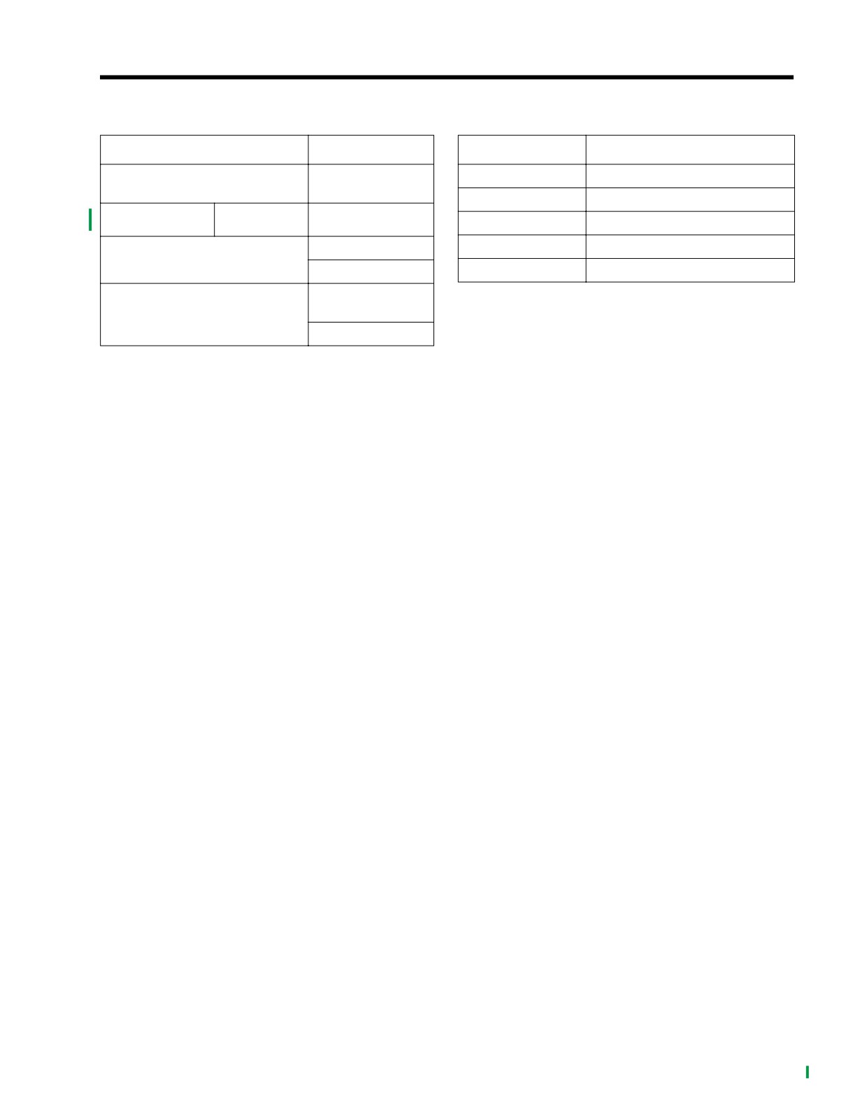
Table 7-1. Transmission Data
Table 7-2. Internal Gear Ratios
TRANSMISSION
DATA
GEAR
INTERNAL GEAR RATIOS
5-speed forward -
First
3.21
Type
constant mesh
Second
2.21
Quart
Part No.
SYN3
99824-03/00QT
Third
1.57
24 oz.
Fourth
1.23
Capacity (dry)
710 ml
Fifth
1.00
Approximately
20-24 oz.
Capacity (wet)
590-710 ml
2004 FLHTCSE: Transmission
7-1
HOME
SERVICE WEAR LIMITS
7.2
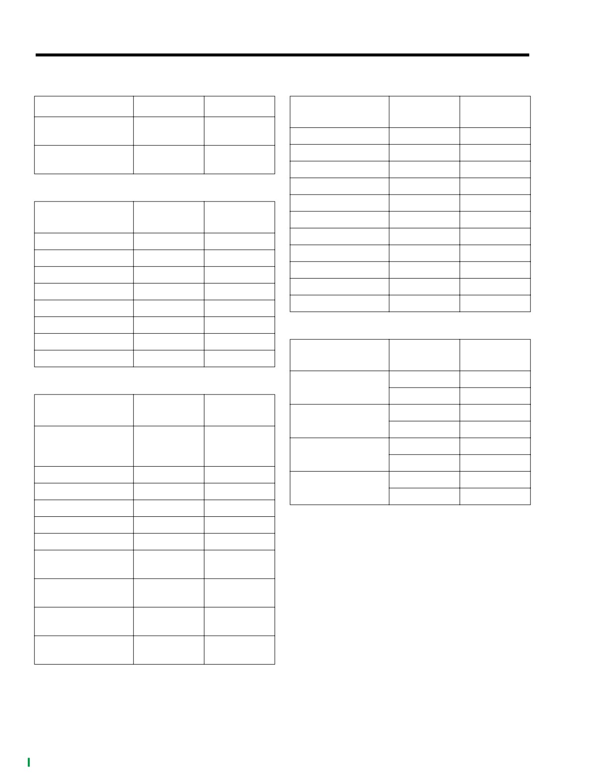
Table 7-3. Shifter Forks
Table 7-6. Countershaft
SHIFTER FORKS
IN.
MM
COUNTERSHAFT
IN.
MM
TOLERANCE
Shifter fork to cam
0.0017-0.0019
0.043-0.048
groove end play
Countershaft runout
0.000-0.003
0.00-0.08
Shifter fork to gear
Countershaft end play
none
none
0.0010-0.0110
0.025-0.279
groove end play
1st gear clearance
0.0003-0.0019
0.008-0.048
1st gear end play
0.0050-0.0039
0.127-0.099
Table 7-4. Mainshaft
2nd gear clearance
0.0003-0.0019
0.008-0.048
MAINSHAFT
IN.
MM
2nd gear end play
0.0050-0.0440
0.127-1.118
TOLERANCE
3rd gear clearance
0.0000-0.0080
0.000-0.203
Mainshaft runout
0.000-0.003
0.000-0.08
4th gear clearance
0.0000-0.0080
0.000-0.203
Mainshaft end play
none
none
4th gear end play
0.0050-0.0390
0.127-0.991
1st gear clearance
0.0000-0.0080
0.000-0.203
5th gear clearance
0.0000-0.0080
0.000-0.203
2nd gear clearance
0.0000-0.0800
0.000-2.032
5th gear end play
0.0050-0.0040
0.127-0.102
3rd gear end play
0.0050-0.0420
0.127-1.067
3rd gear clearance
0.0003-0.0019
0.008-0.048
Table 7-7. Shifter Dogs
4th gear end play
0.0050-0.0310
0.127-0.787
SHIFTER DOG
MINIMUM
MAXIMUM
4th gear clearance
0.0003-0.0019
0.008-0.048
GEARS
CLEARANCE
CLEARANCE
0.035 in.
0.139 in.
Table 7-5. Main Drive Gear (5th)
2nd-5th
0.89 mm
3.53 mm
MAIN DRIVE
IN.
MM
0.035 in.
0.164 in.
GEAR (5TH)
2nd-3rd
0.89 mm
4.17 mm
Bearing fit in
transmission case
0.0003-0.0017
0.008-0.043
0.035 in.
0.152 in.
1st-4th
(loose)
0.89 mm
3.86 mm
Fit in bearing (tight)
0.0009
0.023
0.035 in.
0.157 in.
1st-3rd
Fit in bearing (loose)
0.0001
0.0025
0.89 mm
3.99 mm
Fit on mainshaft
0.0001-0.0009
0.0025-0.023
End play
none
none
Fit in side door (tight)
0.0014-0.0001
0.036-0.0025
Fit on countershaft
0.0008
0.020
(tight)
Fit on countershaft
0.00001
0.0003
(loose)
Fit on mainshaft
0.0007
0.018
(tight)
Fit on mainshaft
0.0001
0.0025
(loose)
7-2
2004 FLHTCSE: Transmission
HOME
TORQUE VALUES
7.3
ITEM
TORQUE
NOTES
Bleeder valve
80-100 in-lbs
9-11 Nm
page 7-5
Clutch fluid line flare nut
80-115 in-lbs
9-13 Nm
page 7-5
Clutch fluid reservoir banjo bolt
17-22 ft-lbs
23-31 Nm
page 7-5
Clutch fluid reservoir cover
6-8 in-lbs
0.7-0.9 Nm
page 7-5
Clutch release cover
120-144 in-lbs
14-16 Nm
page 7-5
Filler plug/dipstick
25-75 in-lbs
2.8-8.5 Nm
page 7-5
Negative battery cable
60-96 in-lbs
6.8-10.9 Nm
page 7-5
Transmission drain plug
14-21 ft-lbs
19-28 Nm
page 7-5
2004 FLHTCSE: Transmission
7-3
HOME
CLUTCH RELEASE COVER
7.4
REMOVAL
9930
1.
Remove filler plug/dipstick.
1
2.
Place a suitable container under transmission. Remove
magnetic drain plug at bottom right of oil pan and drain
transmission lubricant.
2
3
3.
Remove seat. See 2.13 SEAT.
1WARNING
To prevent accidental vehicle start-up, which could
cause death or serious injury, remove maxi-fuse before
proceeding. (00251a).
4.
Remove negative battery cable (black) from negative (-)
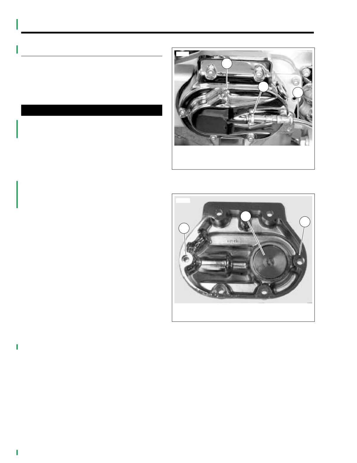
1. Bleeder valve (cap removed)
battery terminal.
2. Flare nut
5.
Remove the right side of the exhaust system. See
3. Clutch fluid line
EXHAUST in the Touring Models Service Manual.
Figure 7-1. Clutch Release Cover
6.
See Figure 7-1. Place a suitable container under clutch
(exhaust system removed)
release cover. Remove cap and open bleeder valve and
loosen flare nut and allow clutch fluid to drain.
7.
Remove flare nut on outside of the clutch release cover.
9923
Remove clutch fluid line and drain line.
IMPORTANT NOTE
2
1
Dispose of clutch fluid in accordance with local regula-
1
tions.
8.
See Figure 7-3. Remove o-ring on end of clutch fluid
line. Discard o-ring.
NOTE
Clutch fluid line o-ring may stick to inside of clutch release
cover. Use a pick to remove old o-ring and other debris.
9.
Remove clutch release cover fasteners, cover and gas-
ket.
10. Clean and inspect clutch release cover. Clean with
denatured alcohol or D.O.T. 5 SILICONE BRAKE FLUID,
1. Hole for locating dowel
only.
2. Secondary clutch actuator
NOTE
Figure 7-2. Inside Clutch Release Cover
If required, replace locating dowels in transmission side door.
11. See Figure 7-2. Disassemble and inspect secondary
clutch actuator. Rebuild if required. See 7.5 SECOND-
ARY CLUTCH ACTUATOR.
7-4
2004 FLHTCSE: Transmission
HOME
INSTALLATION
9994
1. Place a new clutch release gasket on locating dowels
and position clutch release cover on transmission side
door.
2. Install fasteners with the two short fasteners at the top of
the release cover. Tighten fasteners to 120-144 in-lbs
(14-16 Nm).
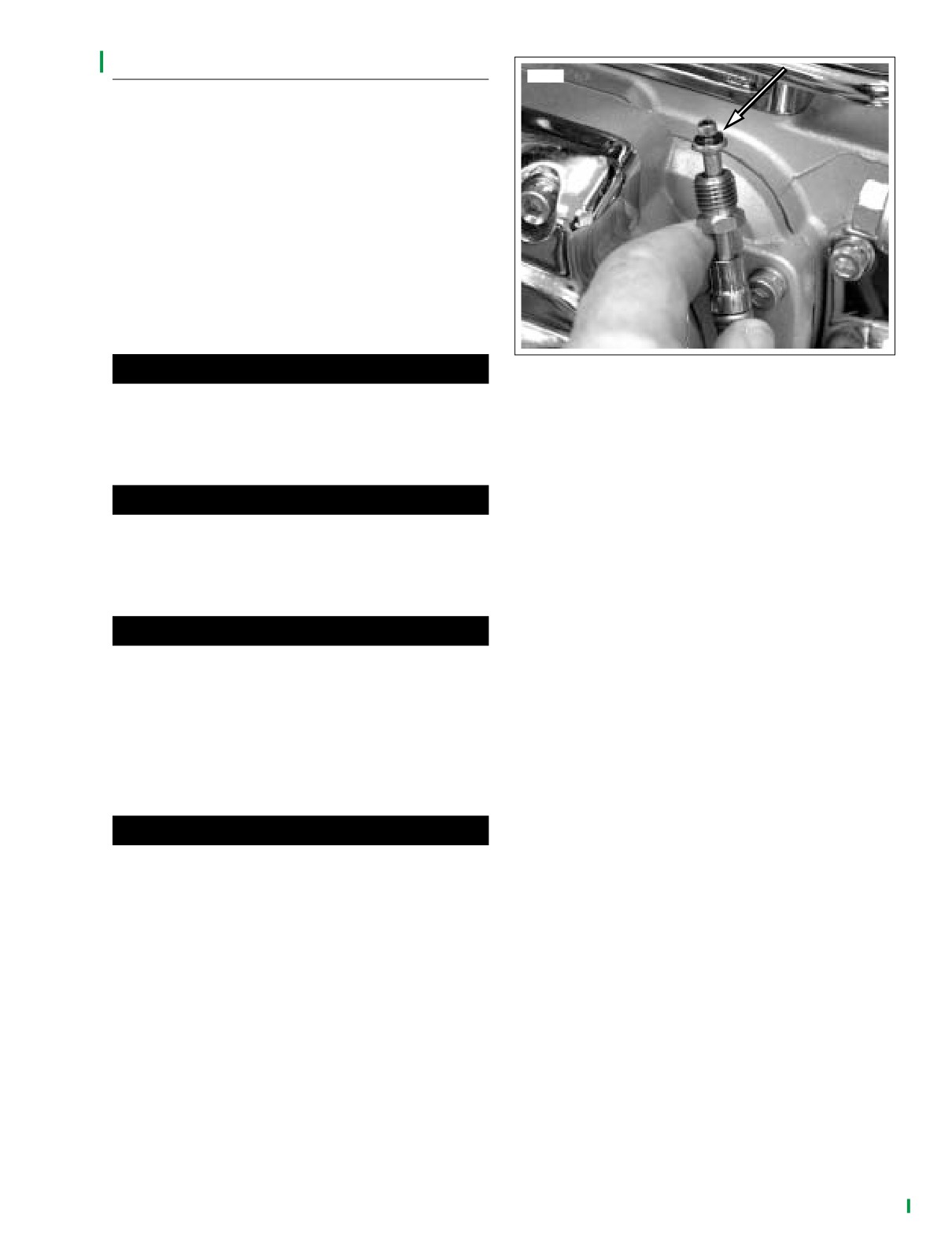
3. See Figure 7-3. Install a new clutch fluid line o-ring on
the end of the clutch fluid line.
4. Install clutch fluid line flare nut to clutch release cover.
Tighten to 80-115 in-lbs (9-13 Nm).
5. Loosen bleeder valve.
1WARNING
Figure 7-3. Clutch Fluid Line O-ring
Be sure NO clutch fluid gets on rear tire, wheel or brakes
8.
Tighten fasteners as follows:
when adding clutch fluid. Traction will be adversely
affected which could result in loss of control of the
a. Reservoir banjo bolt to 17-22 ft-lbs (23-31 Nm).
motorcycle and death or serious injury.
b. Bleeder valve to 80-100 in-lbs (9-11 Nm).
c. Reservoir cover screws to 6-8 in-lbs (0.7-0.9 Nm).
1WARNING
9.
Install bleeder valve cap.
Do NOT allow foreign matter to enter the clutch master
cylinder reservoir. Dirt or debris in the reservoir may
10.
Inspect o-ring on transmission lubricant drain plug and
cause improper operation of the clutch and equipment
replace as necessary. Install drain plug and tighten to
damage.
14-21 ft-lbs (19-28 Nm).
11.
Fill the transmission with
20-24 oz. (590-710 ml) of
transmission lubricant or until the lubricant level on the
1WARNING
dipsitck of the filler plug is at the F (full) mark with the
Direct contact of D.O.T. 5 SILICONE BRAKE FLUID with
motorcycle level and upright and the filler plug resting on
eyes may cause eye irritation, swelling, and redness.
the threads. Use only Harley-Davidson TRANSMISSION
Avoid eye contact. In case of eye contact flush with large
LUBRICANT, Part No. 98853-96 (case/quarts), or Part
amounts of water and seek medical attention immedi-
No. 98852-96 (case/gallons).
ately. Swallowing large amounts of D.O.T. 5 SILICONE
12.
Inspect the filler plug/dipstick o-ring and install filler plug/
BRAKE FLUID may cause digestive discomfort. If swal-
dipstick. Tighten the plug to 25-75 in-lbs (2.8-8.5 Nm).
lowed, seek medical attention immediately. Use in well
ventilated area. KEEP OUT OF REACH OF CHILDREN.
13.
Install exhaust system. See EXHAUST in Touring Mod-
els Service Manual.
1WARNING
14.
Install negative battery cable. Tighten bolt to 60-96 in-
lbs (6.8-10.9 Nm).
The piston in the secondary clutch actuator is under
pressure. Squeezing the clutch hand lever could force
15.
Install seat. See 2.13 SEAT.
the piston out of its housing with sufficient force to
cause death or serious injury.
6. Remove clutch fluid reservoir cover and fill with D.O.T. 5
SILICONE BRAKE FLUID. Allow fluid to fill clutch line
until a steady flow of clutch fluid flows from bleeder
valve. Tighten bleeder valve.
NOTE
When filling an empty clutch fluid line, a Snap-on BASIC
VACUUM BRAKE BLEEDER with a fitting that mates to the
bleeder valve threads can be used to initially draw the fluid
down the clutch line with little or no air in the line.
7. Bleed clutch fluid line. See BLEEDING CLUTCH FLUID
LINE.
2004 FLHTCSE: Transmission
7-5
HOME
SECONDARY CLUTCH ACTUATOR
7.5
REBUILD
8880
1.
Remove the clutch release cover. See 7.4 CLUTCH
1
2
RELEASE COVER.
1WARNING
3
Pressurized air can blow debris into your face and eyes.
Always wear eye protection or a face shield when using
pressurized air. Failure to take adequate safety precau-
tions could result in death or serious injury.
2.
Remove piston.
a. If the bleeder valve was removed, reinstall.
b. Support on a wooden block and apply low pressure
compressed air to clutch fluid line hole to remove
piston from cover bore.
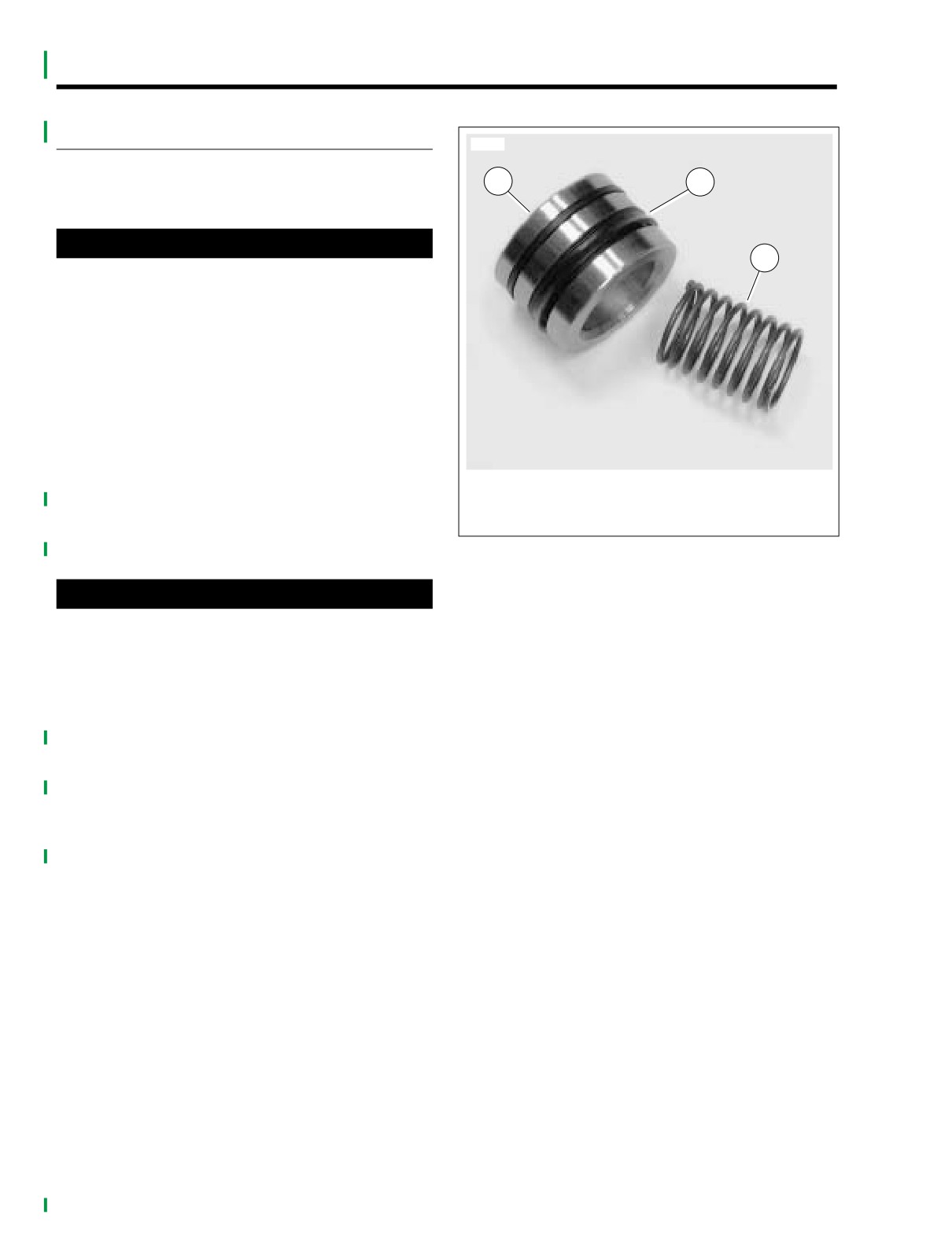
1. Piston
3.
See Figure 7-4. If necessary, wiggle piston from actuator
2. Primary cup
bore to completely remove.
3. Spring
4.
Remove the spring. Discard spring and piston assembly.
Figure 7-4. Secondary Clutch Actuator Components
CAUTION
Damaged pistons or piston bores will leak when reas-
sembled. Do not use metal objects to remove or install
objects from piston bores. Prevent damage to bores by
only using a wooden toothpick when servicing second-
ary clutch actuator.
5.
Lubricate new piston assembly and piston bore with the
service kit lubricant.
6. Install new spring.
7.
While pushing piston into actuator bore, use a wooden
tooth pick or the end of a cable wrap to prevent primary
cup from rolling over.
7-6
2004 FLHTCSE: Transmission
HOME
TURN SIGNALS
8.1
REMOVAL
f1418x2x
1. Remove outer fairing. See UPPER FAIRING/WIND
DEFLECTOR, REMOVAL. Locate front turn signal con-
nector (6-place Multilock) on inboard side of left fairing
bracket.
2. Depress button on socket terminal side of connector and
pull apart pin and socket halves.
3. Remove appropriate terminals from socket housing.
Table 8-1. Front Turn Signal Lamps [31]
Left Side
Right Side
Figure 8-2. Fix Mechanic’s Wire to Socket Terminals
Wire Color
Chamber
Wire Color
Chamber
NOTE
Blue (DOM)
4
Black
1
● Be sure that mechanic’s wire is of sufficient strength to
Violet/Brown
5
Violet/Brown
2
pull terminals through conduit without breaking. Wire
Black
6
Blue (DOM)
3
lengths must also be long enough so that free ends are
not lost in conduit when pulled.
NOTE
●
Liquid glass cleaner may be used to aid in pulling wires
through conduit.
For instructions on properly removing wiring terminals, see
APPENDIX B.2 AMP MULTILOCK ELECTRICAL CONNEC-
6.
Carefully pull turn signal wires to draw socket terminals
TORS, REMOVING SOCKET/PIN TERMINALS of Touring
through both sections of conduit and through hole in
Service Manual.
mounting bracket. For best results, pull one wire at a
time.
10552
7.
Unravel mechanic’s wire to release socket terminals.
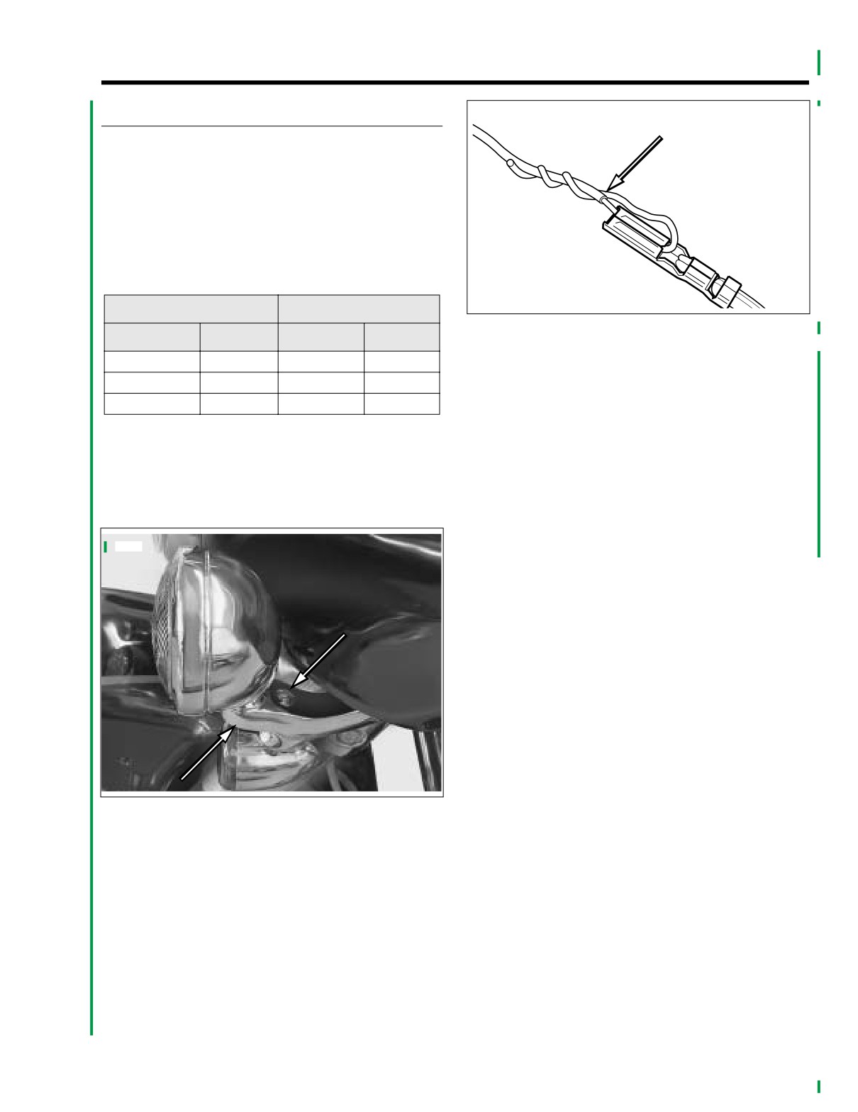
Figure 8-1. Front Turn Signal/Passing Lamps Fastener
Location
4. See Figure 8-1. Remove fastener to release turn signal
lamp from mounting bracket.
5. See Figure 8-2. Obtain equal lengths of string flexible
wire for use as mechanic’s wire. Feed wire through open-
ing in socket terminal and then loop back twisting end
until tightly coiled around longer strand. Repeat step with
remaining socket terminals.
2004 FLHTCSE: Electrical
8-1
HOME
INSTALLATION
1. Lay old turn signal lamp next to new turn signal lamp and
cut wires to length.
2. Strip 3/16 inch (4.8 mm) of insulation off new lamp wires
and crimp on new socket terminals.
NOTE
For instructions on crimping wire terminals, see APPENDIX
B.2 AMP MULTILOCK ELECTRICAL CONNECTORS,
CRIMPING INSTRUCTIONS in Touring Service Manual.
3. Reattach mechanic’s wire to socket terminals and care-
fully pull ends of mechanic’s wire to draw socket termi-
nals back through mounting bracket and conduit.
4.
Carefully remove mechanic’s wire to avoid damage to
terminals.
5. Install terminals into proper location of socket housing.
6.
Mate pin and socket halves of front turn signal connector.
NOTE
For instructions on properly installing wire terminals, see
APPENDIX B.2 AMP MULTILOCK ELECTRICAL CONNEC-
TORS, INSTALLING SOCKET/PIN TERMINALS.
7.
Install fastener to secure turn signal lamp to mounting
bracket. Tighten to 96-120 in-lbs (10.8-13.6 Nm)
8.
Turn Ignition/Light Key Switch to IGNITION and test for
proper operation.
8-2
2004 FLHTCSE: Electrical
HOME
PASSING LAMPS AND BRACKET
8.2
REMOVAL
1. Remove outer fairing. See UPPER FAIRING/WIND-
SHIELD REMOVAL in Touring Models Service Manual.
2. Locate front passing lamp connector.
3. Depress button on socket terminal side of connector and
pull apart pin and socket halves.
4. See Figure 8-1. Remove fasteners from bottom of pass-
ing lamp.
5. Remove complete passing lamp from bracket while
slowly pulling wires through bracket.
INSTALLATION
NOTE
For instructions on properly installing wire terminals, see
APPENDIX B.2 AMP MULTILOCK ELECTRICAL CONNEC-
TORS, INSTALLING SOCKET/PIN TERMINALS in Touring
Models Service Manual.
1. Install new
2. See Figure 8-2. Attach mechanic’s wire to socket termi-
nals and carefully pull ends of mechanic’s wire to draw
socket terminals back through mounting bracket and
conduit.
3. Carefully remove mechanic’s wire to avoid damage to
terminals.
4. Seat passing lamp onto passing lamp bracket, install
passing lamp fasteners and tighten to 15-18 ft-lbs
(20.3-24.4 Nm).
5. Install terminals into proper location of socket housing
6. Mate pin and socket halves of passing lamp connector.
2004 FLHTCSE: Electrical
8-3
HOME
z0064a
19
6
7
8
9
2
1
3
5
10
4
11
19
12
18
13
17
16
15
14
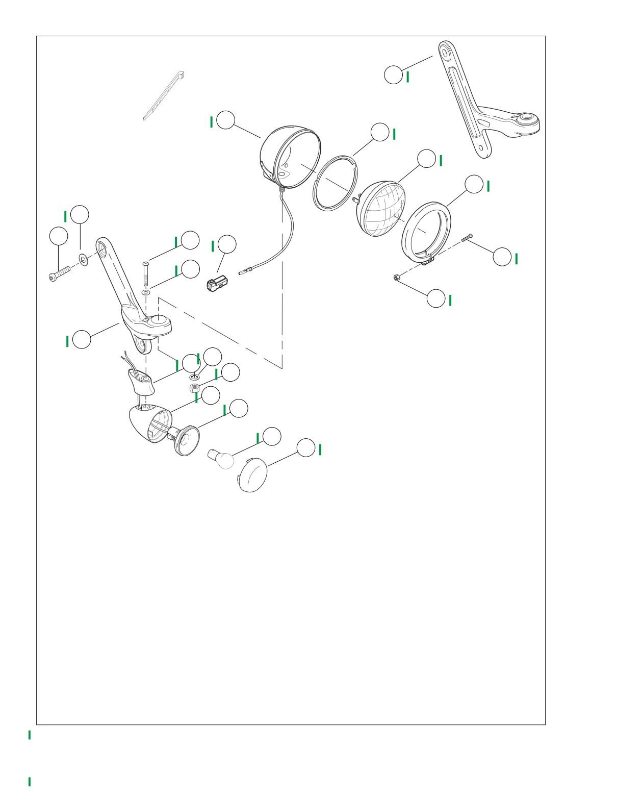
1.
Fastener
2.
Washer
3.
Fastener
4.
Washer
5.
Socket terminal
6.
Housing, passing lamp
7.
Ring, passing lamp
8.
Passing lamp
9.
Bezel ring, passing lamp
10. Fastener
11. Nut
12. Washer
13. Nut
14. Lens, turn signal
15. Bulb, amber
16. Socket, turn signal
17. Housing, turn signal
18. Stand off
19. Bracket
Figure 8-3. Front Turn Signal and Passing Lamp Components
8-4
2004 FLHTCSE: Electrical
HOME
FRONT PASSING LAMP BRACKETS
8.3
REMOVAL
1. See Figure 8-3. Remove passing and front turn signal
lamps per procedures in the manual.
2. Remove fasteners from bracket and remove bracket from
motorcycle.
INSTALLATION
1. Align bracket with mounting holes.
2. Install washers and fasteners.
3. Tighten fasteners to 15-20 ft-lbs (20.3-27.1 Nm).
2004 FLHTCSE: Electrical
8-5
HOME
GARAGE DOOR OPENER
8.4
TRANSMITTER
i04101
Removal
1. Remove outer fairing. See Touring Models Service Man-
ual.
2. Locate transmitter on inner left side of fairing.
3. Disconnect wiring harness connector.
4. Remove transmitter from adhesive tape mount.
Installation
NOTE
Be certain to apply pressure to adhesive tape when installing
transmitter.
1.
Clean surface and apply new transmitter.
2.
Connect wires to harness.
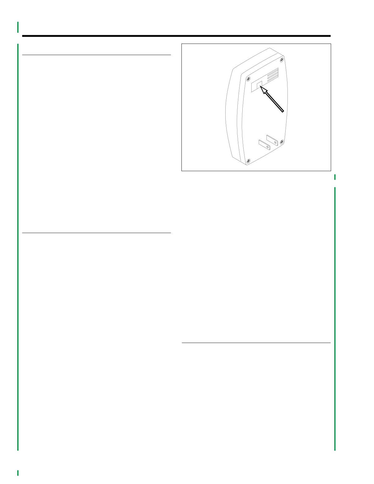
Figure 8-4. Garage Door Opener Receiver, Back View
3.
Verify correct function by verifying that the LED light on
transmitter blinks when the high-low beam switch is acti-
NOTE
vated.
Do not remove original wires from original connections on the
4.
Install outer fairing according to procedure in Touring
door-opener button or on drive-unit terminals.
Models Service Manual.
5. Assemble and install garage-door opener button in its
original location.
RECEIVER
6. Route Harley-Davidson garage-door opener wires con-
nected in step 4 to power outlet selected in step 2.
Installation
7. See Figure
8-4. Plug connector on Harley-Davidson
garage-door opener receiver wires into back of Harley-
1. Unplug power cord from garage door drive unit to prevent
Davidson garage-door opener receiver.
door activation during installation.
8. Plug garage-door opener receiver into selected power
2. Find an unswitched 110V power outlet in garage that is
outlet.
located either highest in the garage, or closest to front of
garage, or both. Locate the Harley-Davidson remote-
9. Plug power cord from garage-door drive unit into power
control garage-door opener receiver here.
outlet.
10. Press wall-mounted garage-door-opener button to test
NOTE
button operation.
With some brands of garage door opener systems, it may be
necessary to plug in the Harley-Davidson receiver at a loca-
tion some distance away from the door opener. If the Harley-
REMOTE CONTROL GARAGE DOOR
Davidson receiver is plugged in too close to the original
OPENER
opener receiver, effective transmission range may be signifi-
cantly reduced on both systems.
3. Find the two garage-door-activation switch terminals on
FCC Notices
one of these locations:
NOTE
a. The existing wall-mounted, hard wired garage door
opener button
Changes or modifications to this unit not expressly approved
by the manufacturer could void the user’s authority to operate
b. The garage-door drive unit to which the garage-
the equipment.
door-opener button is connected
4. Fasten stripped end of Harley-Davidson garage-door
This equipment has been tested and found to comply with the
opener receiver wires to door-opener terminals that acti-
limits for Class B digital devices pursuant to Part 15, Subpart
vate door opener drive unit. Refer to door-opener manu-
B of the FCC Rules. These limits are designed to provide rea-
facturer’s documentation for terminal locations and
sonable protection against harmful interference in a residen-
connections.
tial environment. This equipment generates, uses, and can
radiate radio frequency energy, and if not installed and used
in accordance with the instruction manual, may cause harm-
ful interference to radio communications. However, there is no
8-6
2004 FLHTCSE: Electrical
HOME
guarantee that interference will not occur in a particular instal-
Program the Receiver and Transmitter
lation. If this equipment does cause harmful interference to
radio or television reception, which can be determined by
The receiver must be programmed to receive the transmitter
turning the equipment off and on, the user is encouraged to
frequency. This process may require two people, depending
try to correct the interference by one or more of the following
on how far apart the receiver and transmitter are during the
measures.
programming process.
1.
Check that a red light is visible on the front of the Harley-
•
Reorient or relocate the receiving antenna.
Davidson garage door opener receiver, indicating power
to the receiver.
•
Increase the distance between the equipment and the
receiver.
i04102
•
Connect the equipment to an outlet on a circuit different
from that to which the receiver is connected.
•
Consult the dealer or an experienced radio/TV technician
for help.
NOTE
With some brands of garage door opener systems, it may be
necessary to plug in the Harley-Davidson receiver at a loca-
tion some distance from the door opener. If the Harley-David-
son receiver is plugged in too close to the original opener
receiver, effective transmission range may be significantly
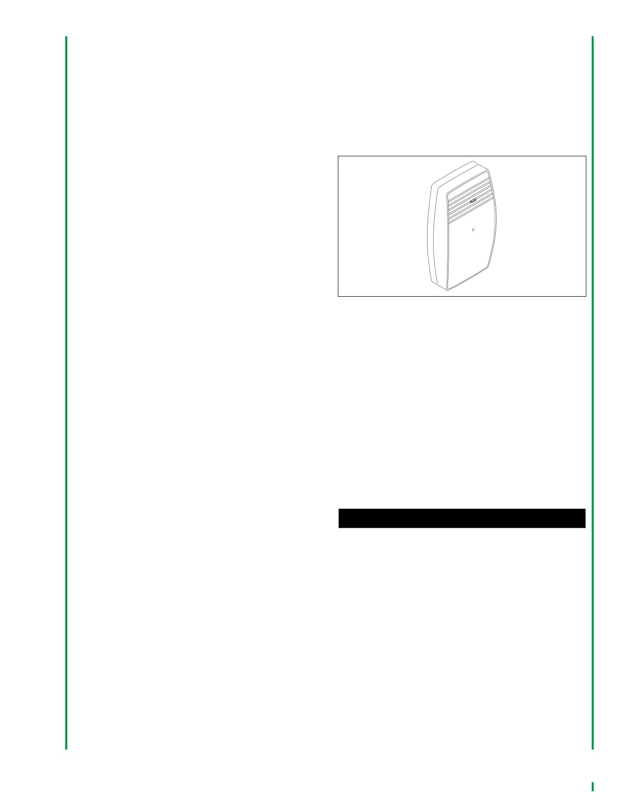
Figure 8-5. Garage Door Opener Receiver, Front View
reduced on both systems.
2.
See Figure 8-5. Press and hold the Set button the Har-
11. Find the two garage door activation switch terminals on
ley-Davidson garage door opener receiver. The LED
one of these locations:
blinks continuously while the Set button is pressed.
a. The existing wall mounted, hand wired garage door
3.
Set the motorcycle ignition switch to IGN. Switch the
opener button.
headlamp beam switch using one of these sequences:
b. The garage door drive unit to which the garage door
a. Starting from Low beam, switch High, then Low
opener button is connected.
b. Starting from high beam, switch Low, then High
12. Fasten the stripped end of the Harley-Davidson garage
NOTE
door opener receiver wires to the door opener terminals
that activate the door opener drive unit. Refer to the door
When the receiver receives a signal from the transmitter, the
opener manufacturer’s documentation for terminal loca-
LED on the transmitter turns off.
tions and connections.
4.
Release the Set button on the receiver.
NOTE
Do not remove original wires from the original connections on
1WARNING
the door opener button or on the drive unit terminals.
Check for proper lighting and switch operation before
riding motorcycle. Visibility is a major concern for motor-
13. Assemble and install the garage door opener button in its
cyclists. Failure to have proper lighting and signal lamp
original location.
operation could result in death or serious injury.
14. Route the Harley-Davidson garage door opener receiver
NOTE
wires connected in Step 4 to the power outlet selected in
Step 2.
Clear all obstructions away from between the transmitter and
receiver before testing the operation of the garage door
15. See Figure 8-5. Plug the connector on the Harley-David-
opener.
son garage door opener receiver wires into the back of
the Harley-Davidson garage door opener receiver.
5. Test the garage door opener, high beam, and low beam
headlamp operation.
16. Plug the garage door opener receiver into the selected
power outlet.
NOTE
17. Plug the power cord from the garage door drive unit into
When the transmitter is activated by toggling the headlamp
the power outlet.
switch, the red LED on the transmitter illuminates for one sec-
ond to indicate that the transmitter is functioning correctly.
18. Press the wall mounted garage door opener button to set
the button operation.
6. Set the motorcycle ignition switch to OFF.
2004 FLHTCSE: Electrical
8-7
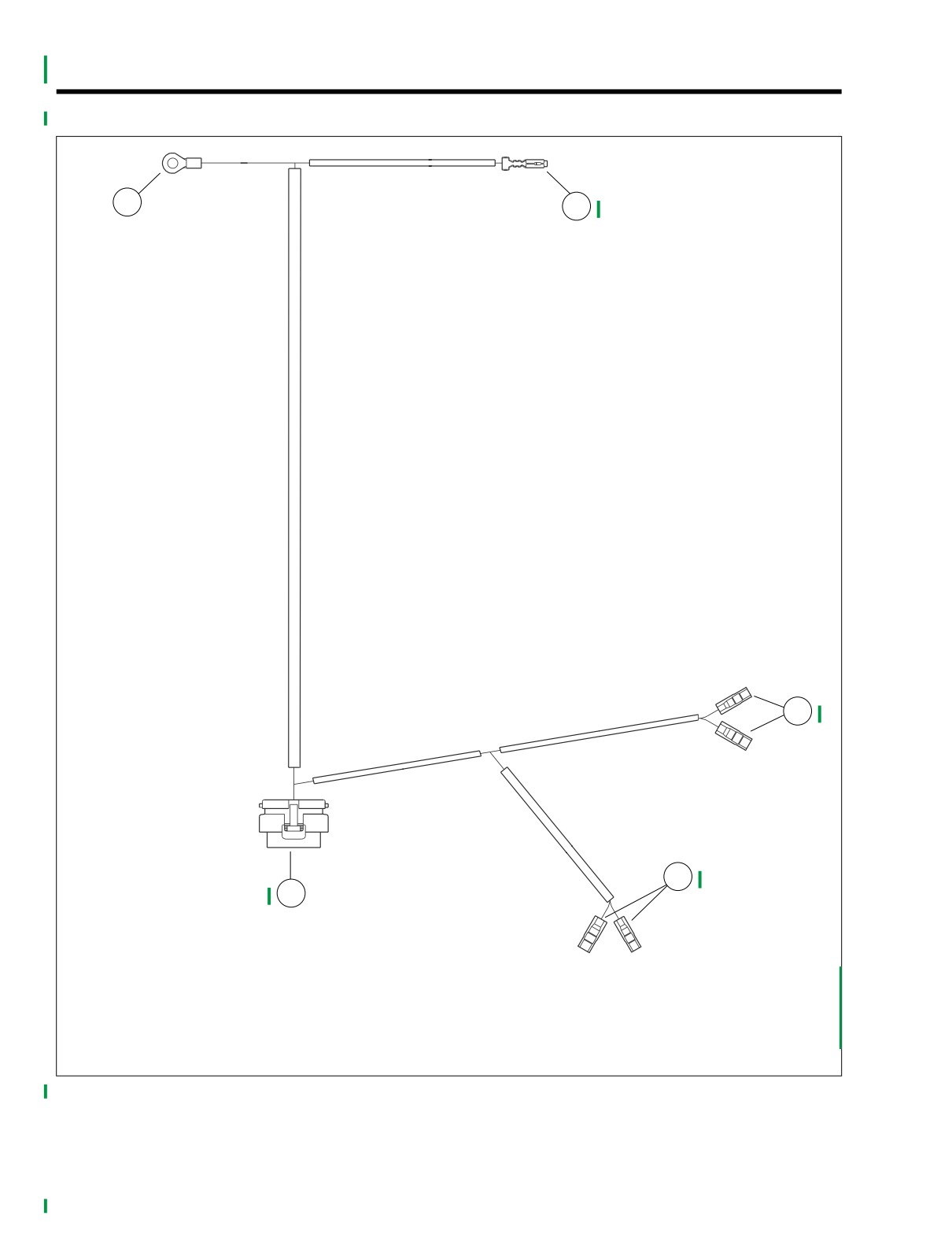
HOME
WIRING HARNESS OVERLAY
8.5
f2282x0x
1
2
3
4
5
1.
Ground stud (left) [GRND1]
2.
Fuse relay block (cavity 2H) [64]
3.
Speaker, front (left) [35]
4.
Speaker, front (right) [34]
5.
Main harness connection [27]
Figure 8-6. Wiring Harness Overlay
8-8
2004 FLHTCSE: Electrical