Harley Davidson 2004 Touring Models. Service Manual - page 61
HOME
ENGINE LUBRICATION
1.2
GENERAL
CAUTION
1
Your motorcycle comes equipped with Screamin’ Eagle
Prolonged or repeated contact with used motor oil may
ENGINE LUBRICATION
be harmful to skin and could cause skin cancer. Promptly
SYN3 Synthetic Motorcycle Lubricant. If SYN3 is not avail-
wash affected areas with soap and water.
able and addition of motor oil is required, the first choice
would be to add H-D® 360 SAE 20W50 to the SYN3 for
engine lubrication. Although H-D
360 is compatible with
1CAUTION
SYN3, we suggest the mixture of the fluids be changed as
If swallowed, do not induce vomiting. Contact a physi-
soon as possible.
cian immediately. In case of contact with eyes, immedi-
If H-D 360 is not available, the second choice would be to add
ately flush with water. Contact a physician if irritation
an acceptable diesel engine oil. We again suggest the mix-
persists.
ture of the fluids be changed as soon as possible. DO NOT
add diesel engine oil to the primary chaincase or transmis-
sion.
CAUTION
To switch lubricant to H-D 360, completely drain the SYN3
Do not switch lubricant brands indiscriminately because
before filling with H-D 360. A residual amount of fluid will
some lubricants interact chemically when mixed. Use of
remain. It is not required to flush out the residual fluid.
inferior lubricants can damage the engine. (00184a)
Refer to Table 1-1. If it is necessary to add oil and Screamin’
Eagle® SYN3 Synthetic Motorcycle Lubricant is not available,
use an oil certified for diesel engines.
Acceptable diesel engine oil designations include:
•
CF-4
•
CG-4
•
CH-4
•
CI-4
The preferred viscosities for the diesel engine oils, in
descending order are:
•
20W50
•
15W40
•
10W40
At the first opportunity, see a Harley-Davidson dealer to
change back to 100 percent Harley-Davidson oil.
Table 1-1. Recommended Engine Oils
HARLEY-DAVIDSON
HARLEY-DAVIDSON
LOWEST AMBIENT
COLD WEATHER STARTS
VISCOSITY
TYPE
RATING
TEMPERATURE
BELOW 50˚ F (10˚ C)
Screamin’ Eagle®
SAE 20W50
HD 360
Above 40˚ F (4˚ C)
Excellent
SYN3 Synthetic
Motorcycle Lubricant
HD Multi-grade
SAE 10W40
HD 360
Below 40˚ F (4˚ C)
Excellent
HD Multi-grade
SAE 20W50
HD 360
Above 40˚ F (4˚ C)
Good
HD Regular heavy
SAE 50
HD 360
Above 60˚ F (16˚ C)
Poor
HD Extra heavy
SAE 60
HD 360
Above 80˚ F (27˚ C)
Poor
1-2
2004 FLHTCSE: Maintenance
HOME
CRITICAL FASTENERS
1.3
INSPECTION
Inspect critical fasteners, except head bolts:
● At the first scheduled service interval.
● At every 10,000 mile (16,000 km) service interval there-
after.
Refer to Table 1-2. Tighten all critical fasteners, except head
bolts, to service manual specifications. Replace any dam-
aged or missing hardware.
2004 FLHTCSE: Maintenance
1-3
HOME
Table 1-2. Critical Fasteners
COMPONENT
FASTENER
TORQUE
Axle
Front axle nut
50-55 ft-lbs
68-75 Nm
Rear axle cone nut
95-105 ft-lbs
129-142 Nm
Brakes
Banjo bolts
17-22 ft-lbs
23-30 Nm
Brake bleeders
80-100 in-lbs
9-11 Nm
Front brake disc mounting screws
16-24 ft-lbs
22-33 Nm
Front brake caliper mounting bolts
28-38 ft-lbs
38-52 Nm
Brake caliper pad pins
180-200 in-lbs
20-23 Nm
Rear brake disc mounting screws
30-45 ft-lbs
41-61 Nm
Rear master cylinder mounting nut
30-40 ft-lbs
41-54 Nm
Reservoir cover screws
6-8 in-lbs
0.7-0.9 Nm
Front forks
Axle holder nuts
132-180 in-lbs
14.9-20.3 Nm
Hand controls
Clutch master cylinder/handlebar clamp
60-80 in-lbs
6.8-9.0 Nm
Brake master cylinder/handlebar clamp screws
60-80 in-lbs
6.8-9.0 Nm
Upper/lower switch housing screws
35-45 in-lbs
4-5 Nm
Handlebars
Lower clamp (riser) bolts
30-40 ft-lbs
40.7-54 Nm
Pivot shaft
Locknuts
40-45 ft-lbs
54-61 Nm
Swingarm bracket bolts
34-42 ft-lbs
46-57 Nm
Engine
Engine mounting bracket to cylinder head bolts
35-40 ft-lbs
48-54 Nm
Top stabilizer link to top engine mounting bracket bolt
18-22 ft-lbs
24-30 Nm
Top stabilizer link to frame weldment bolt
18-22 ft-lbs
24-30 Nm
Front stabilizer link to frame weldment bolt
18-22 ft-lbs
24-30 Nm
Front stabilizer link to front engine mounting bracket
18-22 ft-lbs
24-30 Nm
bolt
Center front engine mounting bracket to rubber mount
15-20 ft-lbs
20-27 Nm
bolt
Front engine mount to frame crossmember bolts
15-20 ft-lbs
20-27 Nm
Engine to front engine mounting bracket bolts
33-38 ft-lbs
45-52 Nm
Engine to transmission bolts
30-35 ft-lbs
41-48 Nm
Clutch
Banjo bolts
17-22 ft-lbs
23-30 Nm
Clutch fluid line flare nut
80-115 in-lbs
9-13 Nm
Secondary actuator bleeder valve
80-100 in-lbs
9-11 Nm
Reservoir cover screws
6-8 in-lbs
0.68-0.90 Nm
1-4
2004 FLHTCSE: Maintenance
HOME
SPECIFICATIONS
2.1
Table 2-1. Dimensions
Table 2-3. Capacities
ITEM
IN.
MM
ITEM
U.S.
METRIC
Wheel Base
63.5
1613
Fuel Tank (gallons)
Total
5
18.9
Overall Length
91.9
2334
Reserve
0.9 Gal.
3.4 Liters
Overall Width
38.5
977.9
Oil Tank (quarts)
Road Clearance
4.21
106.9
with filter
4 Quarts
3.78 Liters
Overall Height
51.75
1314.45
Transmission
20-24
591-710 Mil-
(Ounces, approximate)
Ounces
liliters
Saddle Height*
26.7
678
Primary Chaincase
* With 180 Lb. Rider
(Ounces, approximate)
32 Ounces
946 Mililiters
Left
Right
Left
Right
Front Fork (Ounces)
314
314
10.6
10.6
ml
ml
Table 2-2. Weight
ITEM
LBS.
KG
DRY WEIGHT**
776/788
352.3/357.8
GVWR
1259
572
GAWR - Front
500
227
GAWR - Rear
827
375
** As shipped from the factory
NOTE
Gross Vehicle Weight Rating (GVWR) (maximum allowable
loaded vehicle weight) and corresponding Gross Axle Weight
Ratings (GAWR) are given on a label located on the inside of
the right front frame downtube.
2004 FLHTCSE: Chassis
2-1

HOME
TORQUE VALUES
2.2
ITEM
TORQUE
NOTES
Actuator bleeder valve
80-100 in-lbs
9-11 Nm
page
2-24
Actuator bleeder valve
80-100 in-lbs
9-11 Nm
page
2-25
Banjo bolt
17-22 ft-lbs
23-31 Nm
page
2-24
Banjo bolt
17-23 ft-lbs
23-31 Nm
page
2-25
Brake caliper pad pins
180-200 in-lbs
21-22 Nm
page
2-6
Brake fluid reservoir cover
6-8 in-lbs
0.7-0.9 Nm
page
2-6
Brake pedal to brake arm
25-29 ft-lbs
34-39 Nm
page
2-9
Clutch fluid line flare nut
80-115 in-lbs
9-13 Nm
page
2-24
Clutch fluid line flare nut
80-115 in-lbs
9-13 Nm
page
2-25
Clutch fluid reservoir cover
6-8 in-lbs
0.7-0.9 Nm
page
2-21
Clutch master cylinder banjo bolt
17-22 ft-lbs
23-31 Nm
page 2-21
Clutch reservoir cover screws
6-8 in-lbs
0.7-0.9 Nm
page
2-24
Clutch reservoir cover screws
6-8 in-lbs
0.7-0.9 Nm
page
2-25
Fender mounting bolt
15-20 ft-lbs
20.4-27.1 Nm
page
2-28
Filler strip
15-20 ft-lbs
20.4-27.1 Nm
page
2-30
Footboard hinge bolts
84-108 in-lbs
9.5-12.2 Nm
page
2-7
Footboard hinge bolts
84-108 in-lbs
9.5-12.2 Nm
page
2-7
Front axle cover set screw
60-84 in-lbs
6.8-9.5 Nm
page
2-10
Handlebar clamp screws
71-80 in-lbs
8-9 Nm
page
2-21
Handlebar top clamp
12-16 ft-lbs
16.3-20.3 Nm
page
2-16
Left footboard brackets
15-20 ft-lbs
20.4-27.1 Nm
page 2-7
Pad pins
180-200 in-lbs
21-22 Nm
page
2-6
Passenger backrest docking points
15-20 ft-lbs
20.4-27.1 Nm
page 2-28
Passenger backrest mounting bracket
15-20 ft-lbs
20.4-27.1 Nm
page 2-30
Passenger mounting bracket fasteners
15-20 ft-lbs
20.4-27.1 Nm
page 2-28
Rear axle cone nut
95-105 ft-lbs
128.9-142.4 Nm
page
2-4
Right footboard brackets
30-35 ft-lbs
41.7-47.4 Nm
page 2-7
Right footboard brackets
30-35 ft-lbs
41.7-47.4 Nm
page 2-7
Saddlebag support to support bracket
15-20 ft-lbs
20.4-27.1 Nm
page 2-30
Secondary actuator bleeder valve
80-100 in-lbs
9-11 Nm
page
2-21
Shift lever clamp bolts
90-110 in-lbs
10.2-12.4 Nm
page
2-9
Shift lever peg
144-168 in-lbs
16.3-18.9 Nm
page
2-9
Triple clamp cover backside fasteners
70-110 in-lbs
7.9-12.4 Nm
page
2-11
Triple clamp lower Allen head fastener
120-180 in-lbs
13.5-20.3 Nm
page
2-11
2-2
2004 FLHTCSE: Chassis
HOME
VEHICLE IDENTIFICATION NUMBER (V.I.N.)
2.3
GENERAL
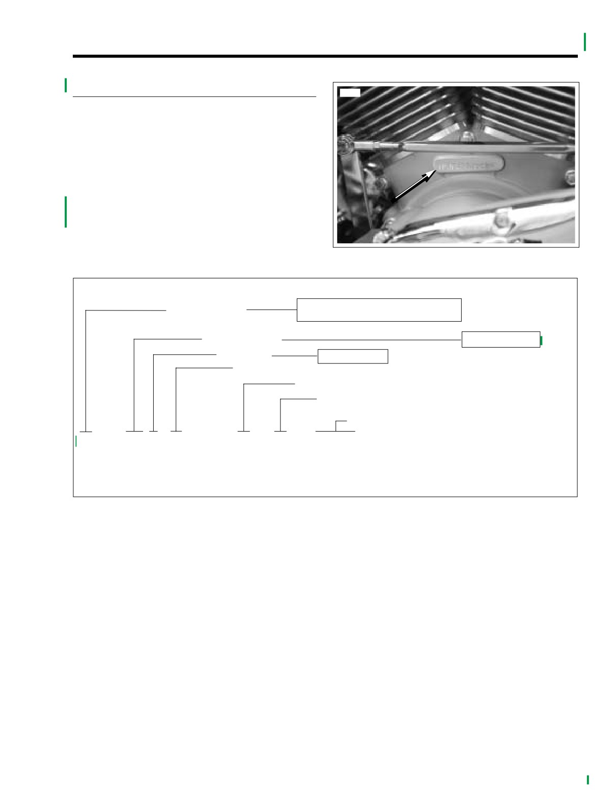
10528
See Figure 2-1. An abbreviated V.I.N. is stamped on the left
side crankcase at the base between the cylinders.
NOTE
Always give the full 17 digit Vehicle Identification Number
when ordering parts or making any inquiry about your motor-
cycle.
See Figure 2-2. The full 17 digit serial, or Vehicle Identifica-
tion Number (V.I.N.) is stamped on the right side of the steer-
ing head and on a label located on the left side of the
steering head.
Figure 2-1. Abbreviated V.I.N. Location
1 - Manufactured for U.S.A.
Market Designation
5 - Manufactured for International Countries
Model Designation
PJ - FLHTCSE
Engine Type
E - 1690 (EFI)
Varies - 1 thru 8
Model Year - 2004
Y - Manufactured in York, PA
K - Manufactured in Kansas City, MO
Sequential Number
1 HD1
PJ E
1
4
Y
950000
*Varies - can be 0 thru 9 or X
Sample V.I.N. as it appears on the steering head - 1HD1PJE1*4Y950000
Sample abbreviated V.I.N. as it appears on the left crankcase - PJE4950000
Figure 2-2. Vehicle Identification Number
2004 FLHTCSE: Chassis
2-3
HOME
REAR WHEEL
2.4
4.
Tilt the bottom of the tire to the right.
REMOVAL
5.
Orient the axle to the lowest cam position and angle the
axle to match angle of rear wheel.
1.
Block motorcycle under frame so rear wheel is off the
ground.
6.
With the larger OD on the outboard side, hold external
spacer between the rear fork and belt sprocket. Slide the
2.
Remove saddlebags. See SADDLEBAG in Touring Mod-
axle through left side of rear swingarm, external spacer,
els Service Manual.
and sprocket into the wheel hub.
3.
Remove mufflers. See REAR WHEEL in Touring Models
7.
When the axle emerges from the hub, straighten the
Service Manual.
wheel and push axle through short external spacer, cali-
per bracket and rear fork.
4.
Remove e-clip from groove on right end of rear axle.
8.
Rotate flat on threaded end of axle to the top. With the
5.
Remove cone nut and adjuster cam from axle.
thumb down and the cam forward, install adjuster cam
on end of axle.
6.
Using a soft mallet, gently tap end of axle towards left
9.
Apply a thin film of LOCTITE ANTI-SEIZE to inboard
side to loosen.
side of cone nut. Install cone nut on axle, but finger
7.
Pull the axle out to saddlebag support.
tighten only.
10.
Verify that adjuster cam just contacts weld nub on both
8.
To clear the saddlebag support, rotate the axle to lowest
sides of rear fork. If necessary push wheel forward
cam position and push the bottom of the tire to the right
slightly to achieve the desired result. Snug the cone nut
to angle the assembly in the fender with the left end of
to 15-20 ft-lbs (20-27 Nm).
axle tilted down.
11.
Lower motorcycle to ground.
9.
Pull the axle the rest of the way out.
12.
Rotate weld nut on left side of axle in a clockwise direc-
10.
Pull wheel to release brake disc from caliper. Pry inner
tion.
and outer brake pads back for additional clearance. If
13.
Check belt deflection. See DRIVE BELT under SCHED-
necessary, use a putty knife with a wide thin blade to
ULED MAINTENANCE PROCEDURES.
avoid scratching the brake disc.
14.
When belt deflection is within specifications, hold weld
nut and final tighten cone nut to 95-105 ft-lbs (128.9-
NOTE
142.4 Nm).
Do not operate the rear brake pedal with the rear wheel
15.
With the flat side out, install new e-clip in axle groove.
removed or the caliper pistons may be forced out. Reseating
16.
Install mufflers. See REAR WHEEL in the Touring Mod-
pistons requires disassembly of the caliper.
els Service Manual.
11. Move wheel forward to slip belt off sprocket and remove
wheel from rear fork.
1WARNING
NOTE
After installation of caliper and BEFORE moving motor-
cycle, pump rear brake pedal until pistons push pads
Removal of the rear wheel can be also facilitated by remov-
against the brake disc. If fluid pressure is not pumped
ing the lower shock bolts and dropping the rear fork below
up, the rear brake will not be available the first time it is
the saddlebag support brackets. This provides access to the
used, a situation that could result in death or serious
rear axle.
injury.
17. Press rear brake pedal several times to set brake pads.
INSTALLATION
18. Install saddelbags. See SADDLEBAG in the Touring
Models Service Manual.
1. Place rear wheel in rear swingarm. Slide wheel forward
and slip belt over sprocket.
CAUTION
Do not bend or fold belt backward or into loops smaller
than 5 inches in diameter. Sharp bending can weaken
the belt and cause premature failure.
2.
Seat caliper on anchor weldment of rear swingarm. Posi-
tion wheel in rear fork, so that brake disc is centered
between brake pads.
3.
Coat the axle with LOCTITE ANTI-SEIZE.
2-4
2004 FLHTCSE: Chassis
HOME
REAR BRAKE PADS
2.5
GENERAL
8696
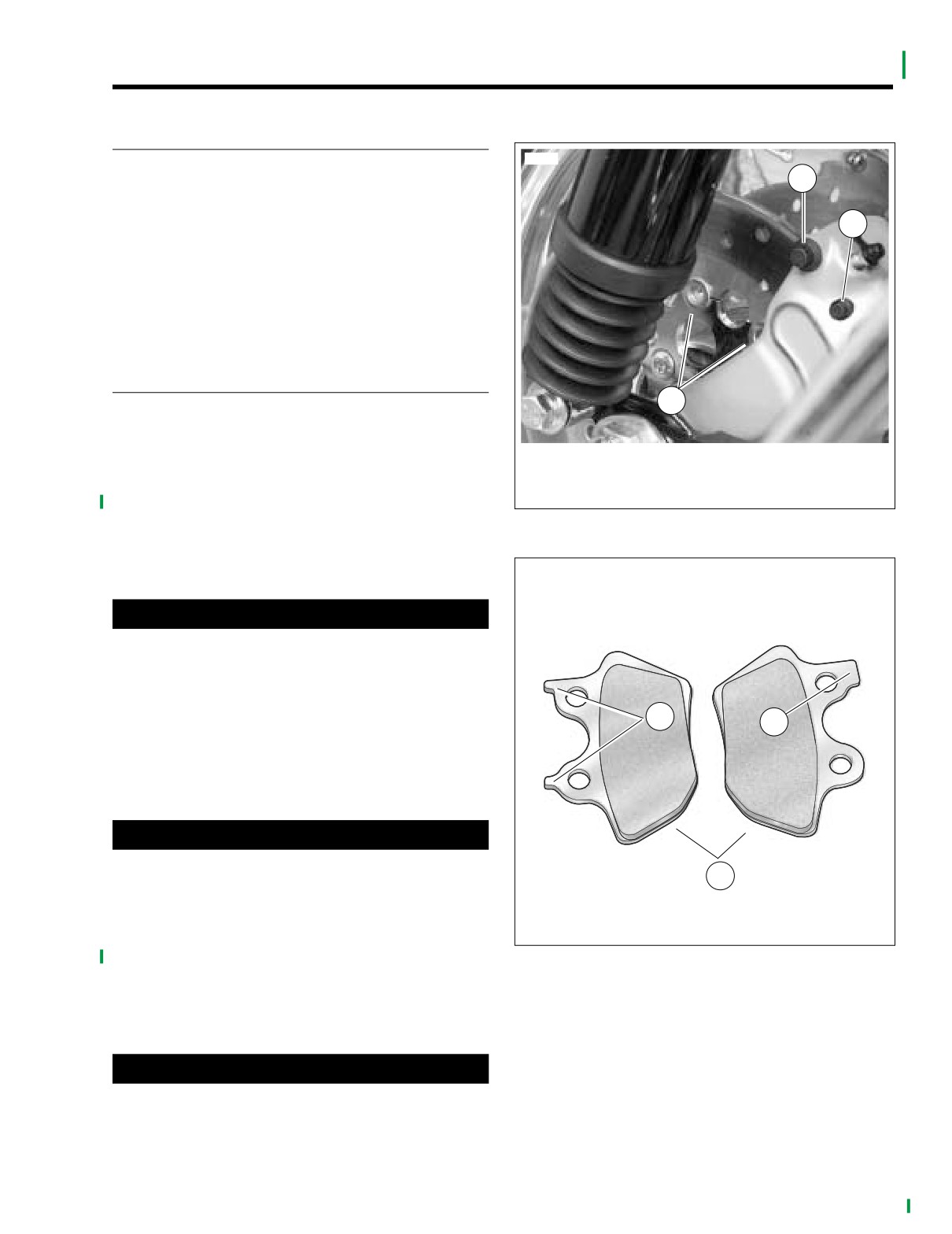
Follow service instructions for INSPECTION, BRAKE DISC
1
THICKNESS/WARPAGE, BRAKE PADS, and BRAKE LINE/
HOSE INSPECTION. See REAR BRAKE CALIPER in Tour-
2
ing Models Service Manual.
Procedures for rear brake pad replacement are similar. How-
ever, the brake pads must be rotated along the arc of the
brake disc to clear the disc rivets and spring washers during
brake pad removal and installation.
REPLACEMENT
3
1. Raise the rear wheel off the ground.
2. Remove right side saddlebag. See SADDLEBAGS,
1.
Bridge bolt
REMOVAL in Touring Models Service Manual.
2.
Pad pin
3.
Spring washer and rivet
3. See Figure
2-3. Loosen both pad pins, but do not
remove.
Figure 2-3. Rear Brake Disc and Caliper
4. Remove two Phillips screws to release cover from rear
master cylinder reservoir.
o0035x0x
CAUTION
Inner brake pad
Outer brake pad
As the pistons are pushed back into the caliper, fluid
level may rise more than 1/8 inch (3.2 mm) and overflow
the reservoir. Watch the fluid level as the pistons are
retracted and remove fluid from the reservoir if neces-
sary.
1
2
5. Pry the inner pad back pushing the pistons into their
bores. Use a putty knife with a wide thin blade to avoid
scoring or scratching the brake disc.
CAUTION
Do not completely pull pad pins from caliper during the
3
next step. Completely removing pad pins at this time will
1.
Two tabs
make assembly difficult.
2.
Single tab
3.
Curved portion faces rear
6. Once the pistons have been retracted, pull the pad pins
part way out to free the inside pad.
Figure 2-4. Rear Brake Pad Orientation
7. Slide the inside pad along the arc of the brake disc to
remove pads from calipers. Note the orientation of the
pad.
1WARNING
Always replace brake pads in pairs. Never replace just
one brake pad. Mismatched brake pads can lead to brake
system damage and loss of braking performance, which
could result in death or serious injury.
2004 FLHTCSE: Chassis
2-5
HOME
8.
See Figure 2-4. Orient new inner brake pad against the
20. Verify that brake fluid level is 1/8 inch (3.2 mm) below top
brake disc. Curved portion must face rear of motorcycle.
of reservoir with master cylinder in a level position. Add
D.O.T. 5 SILICONE BRAKE FLUID, if necessary. Install
9.
Hold brake pad against brake disc and rotate the rear
master cylinder reservoir cover. Install two Phillips
wheel to rotate the pad forward into caliper.
screws to fasten cover to reservoir and tighten to 6-8 in-
10.
Install pad pins, but do not fully tighten.
lbs (0.7-0.9 Nm).
11.
Pump rear brake pedal to move inside pistons out until
21. Install right side saddlebag. See SADDLEBAGS,
they contact inner brake pad.
INSTALLATION in Touring Models Service Manual.
12.
Pry the outside pad back pushing the pistons into their
22. Test operation of brake lamp with the rear brake applied
bores. Use a putty knife with a wide thin blade to avoid
and the ignition/light key switch turned to IGNITION.
scoring or scratching the brake disc.
13.
Verify that inner pad is captured between brake disc and
1WARNING
pistons.
After completing repairs or bleeding the system, always
test motorcycle brakes at low speed. If brakes are not
14.
Completely remove pad pins to free outer brake pad.
operating properly or braking efficiency is poor, testing
Note the orientation of the outer brake pad.
at high speeds may result in death or serious injury.
15.
Orient new outer brake pad against the brake disc.
Curved portion of pad must face rear of motorcycle.
23. Test ride motorcycle. If the brakes fell spongy, bleed the
brake lines. See BLEEDING HYDRAULIC BRAKE
16.
Hold brake pad against brake disc and rotate the rear
LINES in Touring Models Service Manual.
wheel to rotate the pad forward into caliper. If the inside
pad moved during the previous step, reinstall.
17.
Inspect pad pins and clean or replace as required.
18.
Install two pad pins and tighten to 180-200 in-lbs (20.3-
22.6 Nm).
1WARNING
After installation of new pads and BEFORE moving
motorcycle, pump rear brake pedal until pistons push
pads against the brake disc. If fluid pressure is not
pumped up, the rear brake will not be available the first
time it is used, a situation that could result in death or
serious injury.
19. Pump rear brake pedal to move pistons out until they
contact both brake pads. Verify piston location against
pads.
2-6
2004 FLHTCSE: Chassis
HOME
FOOTBOARDS AND CONTROLS
2.6
RIDER FOOTBOARDS
10518
NOTE
Unless the inserts or bottom assemblies are being replaced,
they do not have to be removed from footboard brackets.
Removal
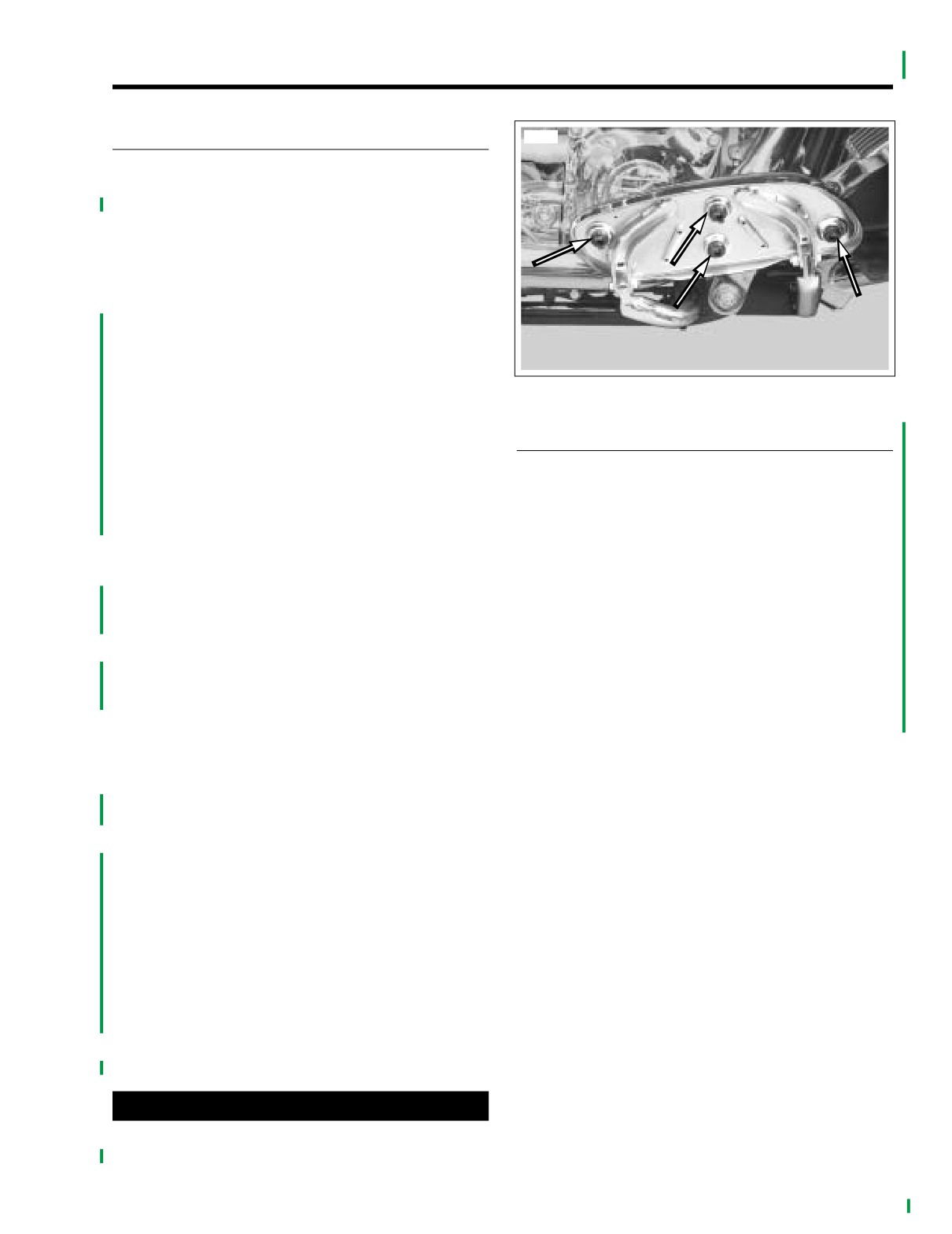
1. See Figure 2-5. With footboards in up position, use a
screwdriver to work cover rubber collars out through
footboards. Remove insert assemblies.
2. See Figure 2-6. Remove right footboard pivot bolts, nuts
and remove footboard bottom assembly.
3. Remove screws, washer, lock washer and right rear foot-
Figure 2-5. Footboard Cover Rubber Collars
board bracket.
4. Remove screws, lock washers, nuts and right front foot-
PASSENGER FOOTBOARDS
board bracket.
5. Remove left footboard pivot bolts, nuts and remove foot-
board bottom assembly.
Removal
6. Remove screws, washers, lock washers and both front
1. See Figure 2-6. Remove socket screw and lockwasher
and rear left footboard brackets.
to remove footboard bracket from swingarm bracket
Installation
Installation
1. See Figure 2-6. Install right front footboard bracket. Posi-
1.
Insert pin on footboard bracket into hole in swingarm
bracket.
tion for rider posture. Install lock washers, washers, nuts
and screws. Tighten screws to 30-35 ft-lbs (41.7-47.4
NOTE
Nm).
Passenger footboards can be adjusted to one of three posi-
2.
Install right rear footboard bracket. Position for rider pos-
tions. To move footboards to a new position, remove plastic
ture. Install lock washer, washer and screw. Tighten
plugs from holes in rear swingarm bracket as necessary.
screws to 30-35 ft-lbs (41.7-47.4 Nm).
2.
Install socket screw with lockwasher.
Tighten
socket
screw to 15-18 ft-lbs (20-24 Nm).
NOTE
The right and left footboard frame mounts allow a small vari-
ance in height and angle.
3.
Install right footboard bottom assembly. Install and
tighten pivot bolts and nut to 84-108 in-lbs (9.5-13.5
Nm).
4.
Install left footboard brackets. Position for rider posture.
Install washers, lock washers, and screws. Tighten
screws to 30-35 ft-lbs (41.7-47.4 Nm).
5.
Install left footboard bottom assembly. Install and tighten
pivot bolts and nut to 84-108 in-lbs (9.5-13.5 Nm).
6. Moisten footboard cover rubber collars with soapy water.
7. With left footboard bottom assembly in up position, hold
new footboard cover in position.
8. From underside of footboard use a pliers to pull each
rubber collar through footboard hole.
9. Repeat for other side.
CAUTION
Avoid contacting chrome surfaces with abrasive materi-
als (stones, sand, etc.) as damage will result.
2004 FLHTCSE: Chassis
2-7
HOME
Disassembly
Assembly
1.
Install footboard bracket. See PASSENGER FOOT-
NOTE
BOARD INSTALLATION, in this section.
If only replacing the rubber pad, refer to step 1 below and
2.
Place spring into hole in footboard bracket. Place ball on
then see steps 4-5 under ASSEMBLY.
top of spring.
1.
Tilt footboard bottom assembly upward. From bottom
3.
Place footboard bottom assembly into position on
side, use a small blade screwdriver to push rubber
bracket and install retaining pins from the outboard side.
beads on pad up through holes in footboard bottom
Using a brass drift and rubber mallet, tap pins until cen-
assembly. Remove insert assembly.
tered in lugs of bracket.
2.
Using a brass drift and rubber mallet, tap two retaining
4.
Moisten rubber beads on new insert assembly with
pins toward center of footboard and remove.
soapy water. Place insert assembly into position on foot-
board bottom assembly. Press firmly on footboard insert
3.
Remove footboard bottom assembly from footboard
in areas of rubber beads.
bracket.
4.
Remove ball and spring from hole in footboard bracket.
5.
Remove footboard bracket from rear swingarm bracket.
See PASSENGER FOOTBOARD, REMOVAL in this sec-
tion.
z0020d
9
22
24
11
6
10
5
21
12
1
2
4
23
13
3
7
14
15
19
15
2
20
14
18
8
15
14
17
16
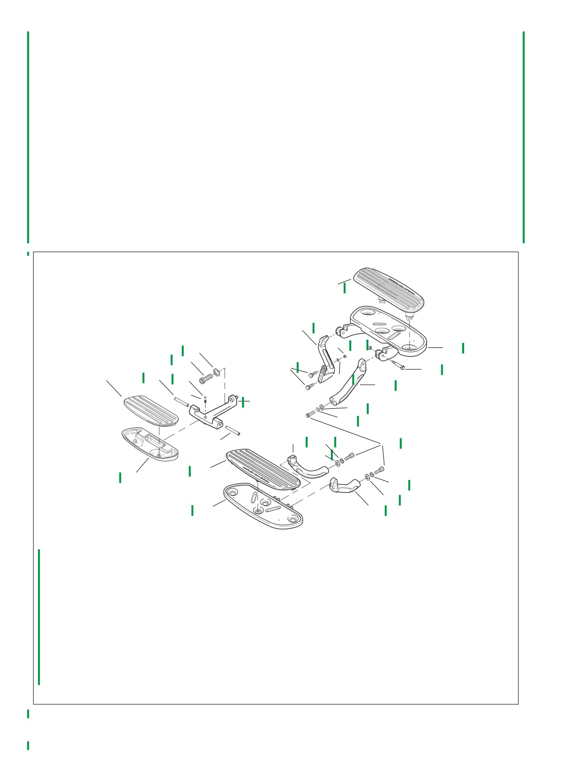
1. Insert Assembly, passenger footboard, right-side
13. Bracket, support, footboard, left-side
(Left-side not shown)
14. Washer
2. Pivot pin
15. Lockwasher
3. Spring
16. Bracket, support, footboard, right-side
4. Ball
17. Bottom assembly, right-side
5. Socket screw
18. Insert assembly, right-side
6. Lockwasher
19. Bracket, support footboard, right rear
7. Bracket, footboard, passenger
20. Screw
8. Bottom assembly, footboard, passenger
21. Screw
9. Insert assembly, rider, left-side
22. Bracket, support footboard, left rear
10. Bottom assembly, with hinge, left-side
23. Lockwasher
11. Nut
24. Locknut
12. Pivot bolt
Figure 2-6. Footboard and Passenger Footrest Components
2-8
2004 FLHTCSE: Chassis
HOME
SHIFT LEVER
Replacement
1. Remove and replace shift lever pegs. Tighten fasteners
to 144-168 in-lbs (16.3-18.9 Nm).
2. If necessary, loosen clamp bolts and pull shift levers off
splined shaft.
3. Position shift levers on splined shaft for rider posture and
tighten clamp bolts to 90-110 in-lbs (10.2-12.4 Nm).
REAR BRAKE PEDAL PAD
Replacement
1. Remove screws (4) and remove brake pedal from brake
arm. Disassemble.
f2287x0x
1
3
4
2
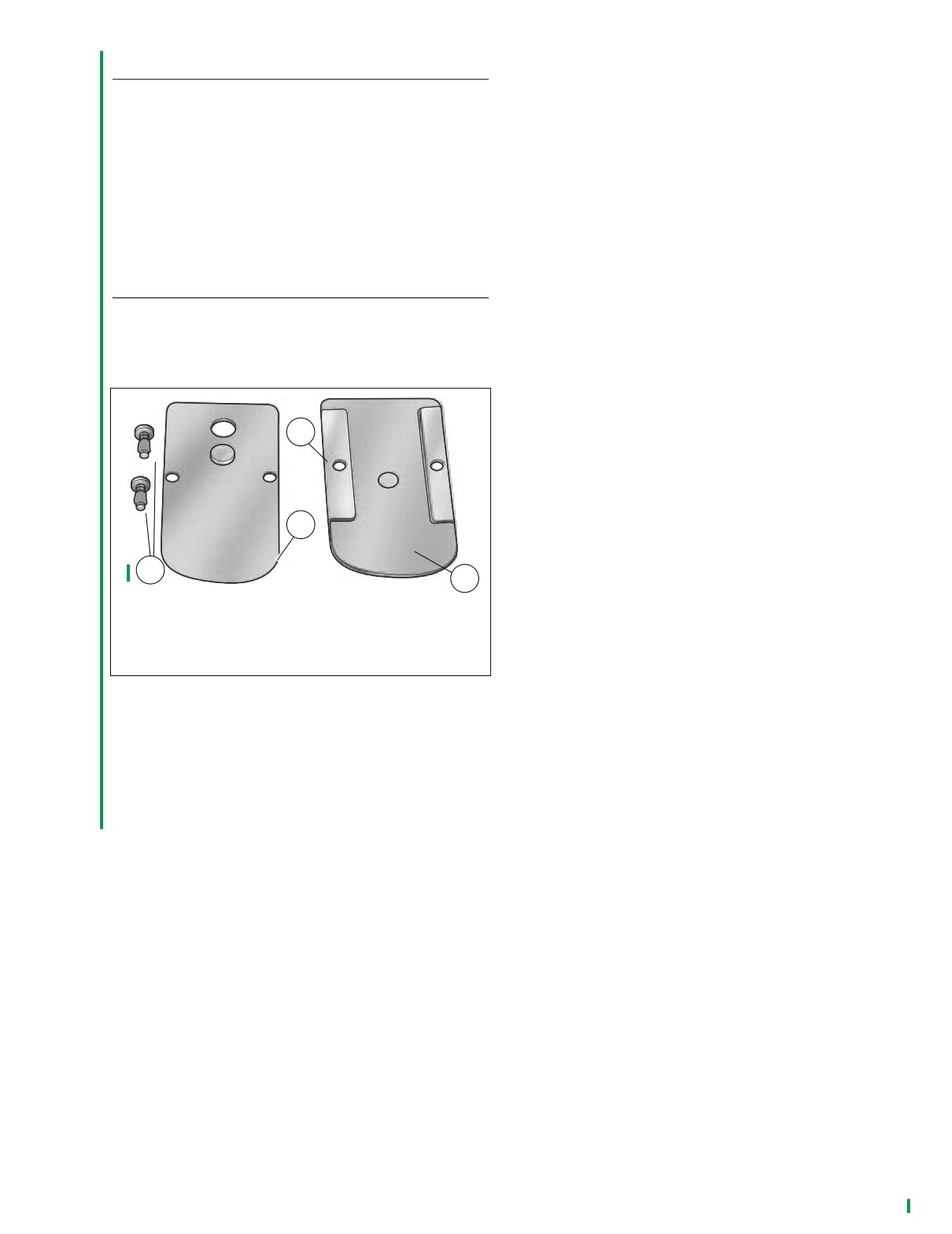
1. Metal brake pedal cover
2. Rubber tread
3. Metal backing plate
4. Screws
Figure 2-7. Rear Brake Pedal
2. See Figure 2-7. Assemble metal brake pedal cover to
rubber tread.
3. Slide metal backing plate into metal brake pedal cover/
rubber tread assembly.
4. Install pedal to brake arm with screws. Tighten screws to
22-29 in-lbs (2.5-3.3 Nm).
2004 FLHTCSE: Chassis
2-9
HOME
FRONT AXLE COVERS
2.7
REPLACEMENT
10522
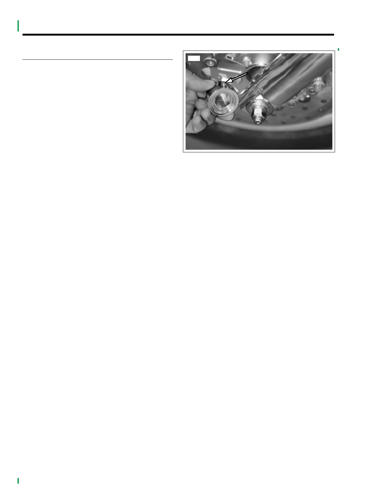
1. See Figure 2-8. Loosen but do not remove set screw
under cover. Remove cover.
2. Remove set screws from cover.
3. Liberally apply LOCTITE THREADLOCKER 262 (red)
(HD-94759-77) to threads of set screw.
4. Orient cover over axle end so that set screw is on the
bottom and will tighten down against a flat on the axle
nut.
5. Install and tighten set screw to 60-84 in-lbs (6.8-9.5
Nm).
Figure 2-8. Front Axle Cover Set Screw
6. Repeat for opposite side.
2-10
2004 FLHTCSE: Chassis
HOME
LOWER TRIPLE CLAMP COVER
2.8
REPLACEMENT
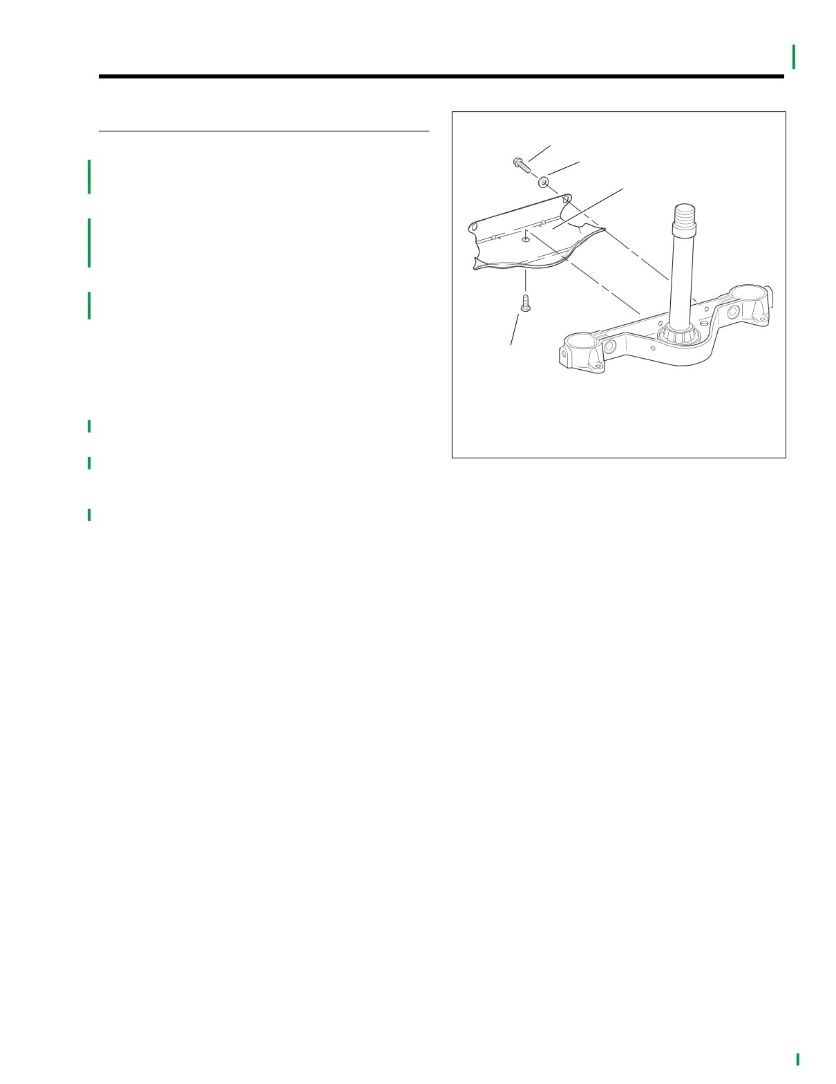
o0041x0x
1
1. See Figure 2-9. Loosen but do not remove the two fas-
2
teners on the backside of cover.
2. Remove the lower Allen fastener through the brake line
3
manifold on bottom.
3. Remove two backside fasteners and washers and
remove cover.
4.
To replace cover, fit cover inside bottom of nacelle and
around triple clamp. Hold in place.
5. Install but do not tighten all three fasteners and washers.
Verify that the cover is snug against the rear surface of
triple clamp.
NOTE
4
Plastic plugs in locator holes in rear surface of triple clamp
can cause interference with the cover. Verify that the center
1.
Backside fasteners
plug has been removed.
2.
Washer
3.
Lower triple clamp cover
6.
Tighten backside fasteners to 70-110 in-lbs (7.9-12.4
Nm).
4.
Lower Allen head fastener
7.
Tighten lower Allen head fastener to 120-180 in-lbs
Figure 2-9. Lower Triple Clamp Cover
(Nm).
8.
Verify that the brake line does not rub on cover. Adjust
line or cover as necessary.
2004 FLHTCSE: Chassis
2-11
HOME
HANDLEBARS
2.9
REMOVAL/REPLACEMENT
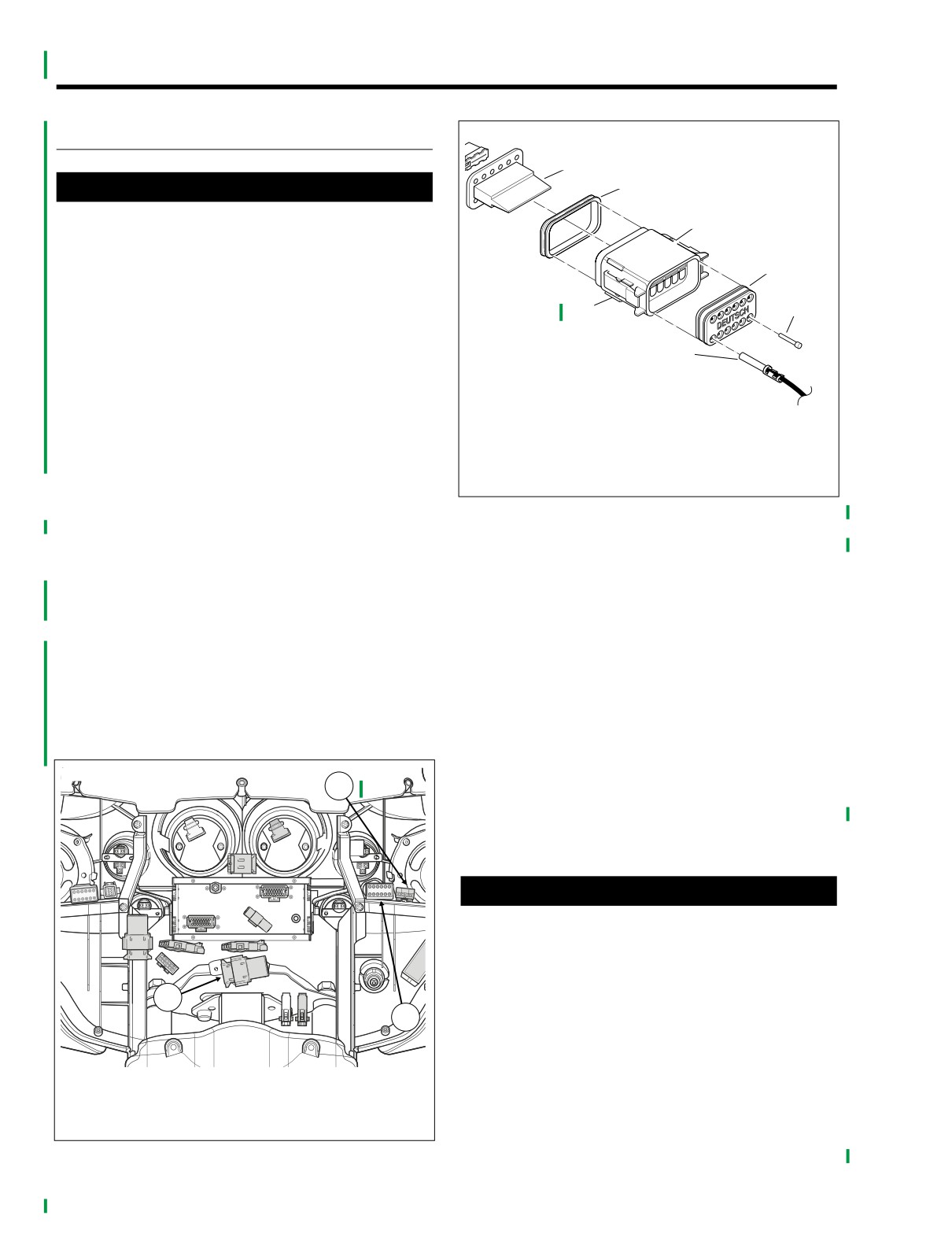
f1915x8x
1
2
1WARNING
To prevent accidental vehicle start-up, which could
3
cause death or serious injury, remove maxi-fuse before
proceeding. (00251a)
4
1.
Remove left side cover.
2.
Remove Maxi-Fuse.
7
5
3.
Remove outer fairing and fairing cap. See FAIRING CAP
in Touring Models Service Manual.
6
1.
Locking wedge
4.
Remove radio chassis. See RADIO REMOVAL in Tour-
2.
Internal seal
ing Models Service Manual.
3.
Socket housing
5.
See Figure 2-10. Separate handlebar switch connectors
4.
Wire seal
[22] and [24] and turn signal multilock connector [31].
5.
Seal pin
6.
Socket terminal
6.
See Figure 2-11. Remove wires from socket side hous-
7.
External latch
ings from socket terminal wires:
a. Use a screw driver to pry out the secondary locking
Figure 2-11. 12-place Deutsch Socket Side Connector
wedges. See DEUTSCH ELECTRICAL CONNEC-
TORS in Touring Models Service Manual.
10. Shorten throttle and idle cable adjustors and pull idle
and throttle cable inserts and elbows from switch hous-
b. See Figure 2-13. Depress internal terminal latches
ing.
and pull socket terminals out of the wire seal.
11. Remove upper and lower fasteners holding right turn
7.
Using mechanic’s wire, neatly wrap the socket terminals
signal and cruise control housings to handlebars.
and wires with 1 or 2 twists to form leaders for turn sig-
12. See Figure 2-14. Use a screwdriver to rotate cable fer-
nal and handlebar switch connector wires.
rules in throttle grip notches. Remove cables from
8.
String wire along the turn signal wire. String sufficient
notches on inboard side of throttle grip and remove
wire to pull conduits through handlebars.
throttle grip from handlebar.
9.
Wrap with electrical tape from the open end of the con-
13. Remove the cables from the housing.
duit past the turn signal lamp sockets to form a leader.
14. Protect chrome and painted surfaces and tie idle and
throttle cables away from chrome and paint finishes.
f2238x8a
Maintain the routing of the cables.
3
15. See Figure 2-12. Insert a 5/32 in. (4 mm) cardboard
between front brake lever and lever bracket.
16. Remove fasteners securing handlebar clamp to master
cylinder and
front brake lever.
CAUTION
See Figure 2-12. Do not remove the 5/32 in. (4 mm) card-
board insert wedged between the brake lever and lever
bracket. Removal will result in damage to the rubber
boot and plunger of the front stoplight switch during
installation of the master cylinder assembly.
1
2
17. Protect chrome and painted surfaces and tie the master
cylinder, reservoir and brake line out of the way.
18. Remove upper and lower fasteners holding left turn sig-
nal and cruise control housings to handlebars.
1. Right
handlebar switch connector [22]
2. Left handlebar switch connector [24]
19. Remove fasteners and washers securing the handlebar
clamp to the clutch lever bracket.
3. Turn signal multilock connector [31]
20. Protect chrome and painted surfaces and tie the master
Figure 2-10.
Turn Signal and Cruise Switch Connectors
cylinder, reservoir and clutch fluid line out of the way.
2-12
2004 FLHTCSE: Chassis
HOME
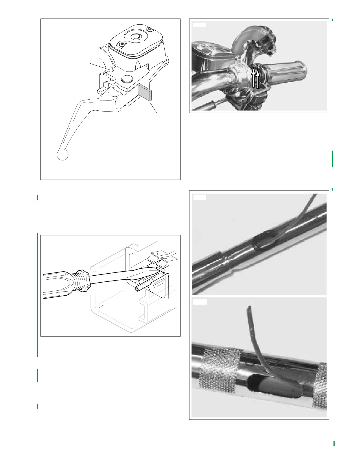
f1225x2x
10521
1
2
Figure 2-14. Throttle and Idle Cable Ferrules
26. If necessary to repair wires, unwrap the electrical tape
and wire from the socket terminals.
27. Repair and replace switches and socket wires as neces-
sary.
1.
Notch for switch housing
NOTE
2.
5/32 in. (4 mm) cardboard
For handlebar switch repair procedures, see HANDLEBAR
SWITCHES in Touring Models Service Manual.
Figure 2-12. Cardboard Insert
21. Remove upper handlebar clamps and lift handlebars,
8689
turn signal housings, and wire harness from motorcycle.
NOTE
If handlebar rubber mounts require service. See HANDLE-
BARS in the Touring Models Service Manual.
o0031x0x
8688
Figure 2-13. Internal Deutsch Terminal Latches
22. Place handlebars and wiring on work bench.
23. Cut wire tie at handlebar.
24. See Figure 2-15. Lightly lubricate conduits and tape with
glass cleaner then pull the left and right side wiring and
conduits from the handgrip ends through the handlebar
and handlebar grommets.
25. If installing original handlebars, leave the wire leader in
each handlebar half. If installing new bars, string wire
leader through grommets on outside ends of bars and
through the center hole.
Figure 2-15. Wire Leader in Handlebars
2004 FLHTCSE: Chassis
2-13
HOME
HANDGRIPS
ASSEMBLY/INSTALLATION
1. Using mechanic’s wire, neatly wrap the socket terminals
NOTE
and wires with a few twists to form leaders for turn signal
It is not necessary to remove the handlebars from the motor-
and cruise control wires and conduit.
cycle to replace the handgrips. Remove the control levers
and control housings according to the instructions in this sec-
NOTES
tion and replace the hand grips.
If installing the original handle bars, use the wire end left in
the handlebar half to wrap the socket terminals.
1.
Replace right hand throttle grip. Slide throttle grip on in
operating position.
2. String wire along the turn signal lamp wire. String suffi-
cient wire to pull conduits through handlebars.
2.
Pry off end cap from left hand grip and using a sharp
blade carefully cut rubber between metal sleeve until the
3. Wrap socket wires with electrical tape.
metal sleeve can be pulled off the bars.
3.
Clean left handlebar end.
1WARNING
NOTE
Without protective grommets around wire entry open-
Before installing left hand grip, remove end cap to prevent
ings in handlebars, wires can rub against sharp metal
trapping air.
edges of opening. A short or broken connection can
cause loss of electrical control which can lead to death
or serious injury.
1WARNING
4.
Lubricate wire conduits with glass cleaner. With the wire
FLAMMABLE, INJURIOUS TO EYES, HARMFUL IF SWAL-
leader, pull wire bundles through grommets and handle-
LOWED, VAPOR HARMFUL. FLAMMABLE: CONTAINS
bar to the handlebars center hole.
METHYL ETHYL KETONE. Use only in well ventilated
areas. Avoid contact with eyes, mucous membranes, and
5.
See Figure 2-16. and Figure 2-17. Orient wires in switch-
prolonged skin contact. KEEP OUT OF REACH OF CHIL-
housings. The right hand RUN and STOP wires are
wrapped over the front of the bars and back and into the
DREN. If swallowed, do not induce vomiting. Call a phy-
sician immediately. This product contains a chemical(s)
handlebar through the grommet. The wires should be to
the outside of the clamping post inside the housing.
known to the State of California to cause cancer or other
reproductive harm.
6.
Loosely install left and right switch housings.
4.
Apply a coat of HARLEY-DAVIDSON ADHESIVE (Part
7.
Pull wire leaders and unwrap the tape and mechanic’s
No. 99839-95) to inside surface of new left hand grip at
wire.
a point 1 in. (25.4 mm) from open end. Apply a coat of
8.
Cable wrap wire conduits at exit from handlebars.
adhesive to handlebar end.
9.
See Figure 2-11. Fit wire seal into back of Deutsch
5.
Immediately push grip completely onto the handlebar
socket housings.
end. Install grip with a twisting motion while aligning the
10. Insert wire color coded socket terminals into numbered
horizontal pattern on the left hand grip to the pattern on
chambers in socket housings:
the right hand grip in the closed position.
a. Hold socket terminal 1 in. (25.4 mm) behind contact
NOTE
barrel.
Do not hesitate when installing left grip or adhesive will dry
b. Gently push socket terminal through hole in wire
before installation is complete. Allow 6-8 hours at 70° F (21˚
seal into chamber until it “clicks” in place.
C) to achieve full cure of the adhesive.
c. Verify that socket will not back out of chamber. Tug
6. Install end caps.
on the wire to confirm that is locked.
2-14
2004 FLHTCSE: Chassis
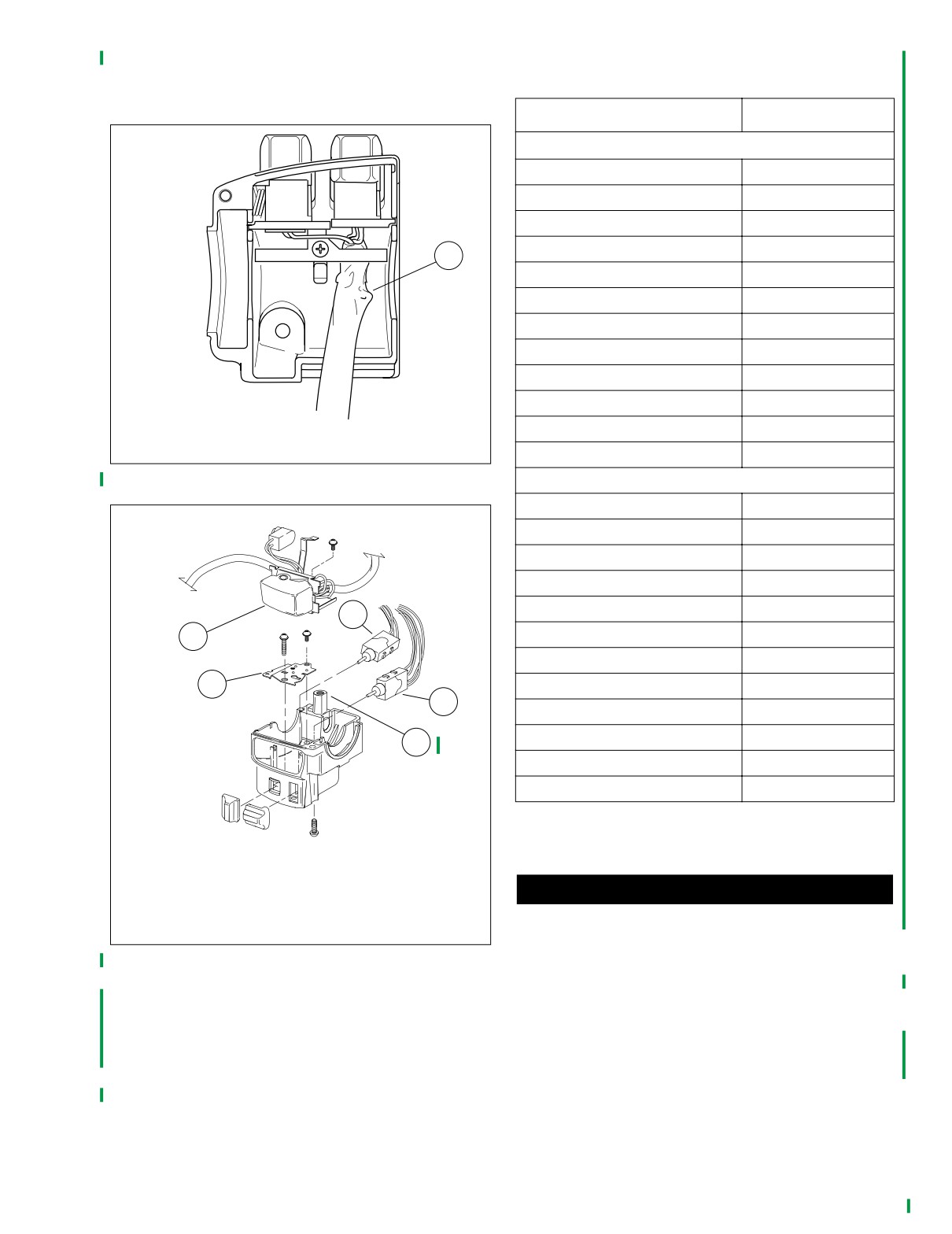
HOME
NOTE
An ELECTRICAL TERMINAL CRIMP TOOL (Part No. HD-
Table 2-4. Handlebar Deutsch Connectors
39965) can be used to install Deutsch pin and socket termi-
nals on wires.
Wire Color
Chamber No.
f1270x2x
RH Connector (12 socket) (BLACK)
Orange/White (O/W)
1
Red/Blue (R/BE)
2
Gray (GY)
3
White/Black (W/BK)
4
1
White/Brown (W/BN)
5
Black/Red (BK/R)
6
Brown/White (BN/W)
7
Gray/White (GY/W)
8
Pink/White (PK/W)
9
Violet/Black (V/BK)
10
White/Blue (W/BE)
11
1. Run/stop switch wiring
Blue/Black (BE/BK)
12
Figure 2-16. Wiring in Upper Right Hand Control Housing
LH Connector (12 socket) (GRAY)
Orange/White (O/W)
1
f1328x2x
Yellow (Y)
2
Blue/White (BE)
3
White (W)
4
White/Violet (W/V)
5
2
1
Yellow/Black (Y/BK)
6
BLANK
7
4
Brown/Black (BN/BK)
8
3
Pink/White (PK/W)
9
Green/Blue (GN/BE)
10
5
Gray/Green (GY/GN)
11
BLANK
12
13. Gently tug on wire ends to verify that all terminals are
1. Right turn signal control and wiring
locked.
2. Cruise control switch
3. Mode select switch
CAUTION
4. Lower bracket
Improperly aligned handlebars can hit tank when turned
5. Clamping post
lock to lock. Verify turning clearance before maneuvering
Figure 2-17. Wiring in Lower Right Hand Control Housing
or riding motorcycle.
14. Carry handlebars with internal wire harness and control
11. Install internal seals on lip of socket housings.
housings to the motorcycle.
12. Snap tapered end of locking wedges into socket hous-
15. Set handlebars on lower clamps and loosely install
ings.
upper handle bar clamps and fasteners. Position wires
so they exit under radio to front of vehicle from between
NOTE
risers.
If the locking wedge does not snap into position, verify that all
terminals are fully seated in the socket housing.
2004 FLHTCSE: Chassis
2-15
HOME
27.
Remove cardboard insert between brake lever and
CAUTION
bracket.
a. Control lever clamps beginning with top fastener to
Never adjust handlebars using excessive force. Doing so
60-80 in-lbs (6.8-9.0 Nm). The gap, if any must be
may result in damage to handlebar.
at clearance flat on handlebar.
NOTE
b. Turn signal and cruise control housings beginning
If handlebars are positioned for a rider of normal size, post-
with bottom fastener to 35-45 in-lbs (4-5 Nm). Rear
pone adjustment until rider has checked their position. If cus-
gap, if any, should be tighter.
tomer requests changing handlebar position, perform the
adjustment before delivering the motorcycle.
28.
Loosely assemble clutch master cylinder/reservoir and
clamp to handlebar. Alternately tighten fasteners until
16. Center handlebars laterally (sideways) in clamps.
clamp is snug to bracket.
17. Snug front fasteners until upper clamp contacts lower
29.
Install left turn signal and cruise control housings.
clamps.
a. Position upper switch housing so wire conduit wraps
18. Position handlebars in normal rider posture.
around front of handlebar.
19. Tighten fasteners in the following order:
b. Verify wires will not be pinched when fasteners are
a. Rear fasteners - 12-16 ft-lbs (16.3-20.3 Nm).
tightened.
b. Front fasteners - 12-16 ft-lbs (16.3-20.3 Nm).
c. Position upper switch housing to wire conduit sets in
20. Push left and right harness Deutsch connectors into the
clearance at bottom of handlebar and upper har-
pin side housings.
ness will not be pinched when fasteners are tight-
21. Remove loosely installed control housing fasteners.
ened.
22. Push throttle and idle control cable inserts into lower
d. Engage lower switch housing tab with notch in
switch housing.
clutch master cylinder reservoir.
NOTE
30.
Install but do not tighten switch housing fasteners.
The smaller idle cable insert is gold while the larger throttle
31.
Position controls for rider posture and tighten fasteners:
cable insert is silver. The inserts only fit their corresponding
a. Clutch master cylinder/reservoir clamp beginning
hold in switch housing.
with top fastener to 60-80 in-lbs (6.8 Nm). Top gap,
23. Slide throttle control grip onto handlebar until it bottoms.
if any, must be at handlebar clearance.
Pull grip back about 1/8 in. (3.2 mm).
b. Turn signal and cruise control housings beginning
24. Use a screwdriver to rotate barrels and fit cables through
with bottom fastener to 35-45 in-lbs (4-5 Nm). Rear
notches in throttle control grip. Be sure cables ride in
gap, if any, should be tighter.
grooves of throttle control grip.
32.
Verify routing of wire conduits, brake line and clutch fluid
line. See FRONT BRAKE LINE in Touring Models Ser-
CAUTION
vice Manual and 2.12 CLUTCH FLUID LINE in this book.
See Figure 2-12. Do not remove 5/32 in. (4 mm) card-
33.
Install right rear view mirror stem through mirror spacer,
board insert wedged between brake lever and lever
and the brake control lever bracket. Install lock washer
bracket. Removal will result in damage to rubber boot
and acorn nut on mirror stem.
and plunger of front stoplight switch during installation
34.
Install left rear view mirror stem through tapered spacer
of master cylinder assembly.
and clutch master cylinder. Install lock washer and acorn
25. Assemble upper and lower control housing to handle-
nut.
bars and brake lever bracket.
35.
With motorcycle upright and with front fork pointed
a. Position upper switch housing so wire conduit wraps
straight ahead, adjust mirrors to clearly reflect area
around outside of handlebar and sets in clearance
behind motorcycle.
at bottom of handlebar.
NOTE
b. Verify that wires will not be pinched when fasteners
Adjust mirrors so a small portion of riders shoulder is visible
are tightened.
in each mirror. This visually establishes the distance of vehi-
c. Verify that throttle and idle control cables work
cles to rear of motorcycle.
freely.
36. Tighten acorn nuts to 144 in-lbs (16.3 Nm).
d. Install switch housing fasteners.
37. Install radio according to procedure in Touring Models
26. Loosely assemble handlebar clamp to front brake control
Service Manual.
lever bracket master cylinder and reservoir.
38. Install outer fairing, wind deflector and fairing cap
a. Engage tab on switch with notch at top of brake
according to procedure in touring Models Service Man-
lever bracket.
ual.
b. Alternately tighten housing and bracket fasteners
39. Install Maxi-Fuse and side cover.
until all components fit and wires route without inter-
ference. fasteners should only be snug.
40. Test clutch lever and front brake lever for pressure and
operation.
c. Verify housing and bracket clamp are tight against
handgrip shoulder/edge of bar.
41. Turn throttle and idle adjusters out.
2-16
2004 FLHTCSE: Chassis
HOME
42. Verify throttle and idle cable routing. Test for correct
operation Adjust as required. See CRUISE CONTROL in
the Touring Models Service Manual.
43. Verify brake and clutch fluid line routing.
44. Turn ignition/light key switch to IGNITION and test
switches for proper operation.
45. Apply brake lever to test stop light lamp.
2004 FLHTCSE: Chassis
2-17