Harley Davidson Softail Delux FLSTN BIKE 2011-2015. Service Manual - page 28
 

  Главная      Harley Davidson     Harley Davidson Softail Delux FLSTN BIKE 2011-2015. Service Manual and Tool Catalog


Search            copyright infringement  


Content      ..     26      27      28      29     ..


Harley Davidson Softail Delux FLSTN BIKE 2011-2015. Service Manual - page 28


1

2

3

3

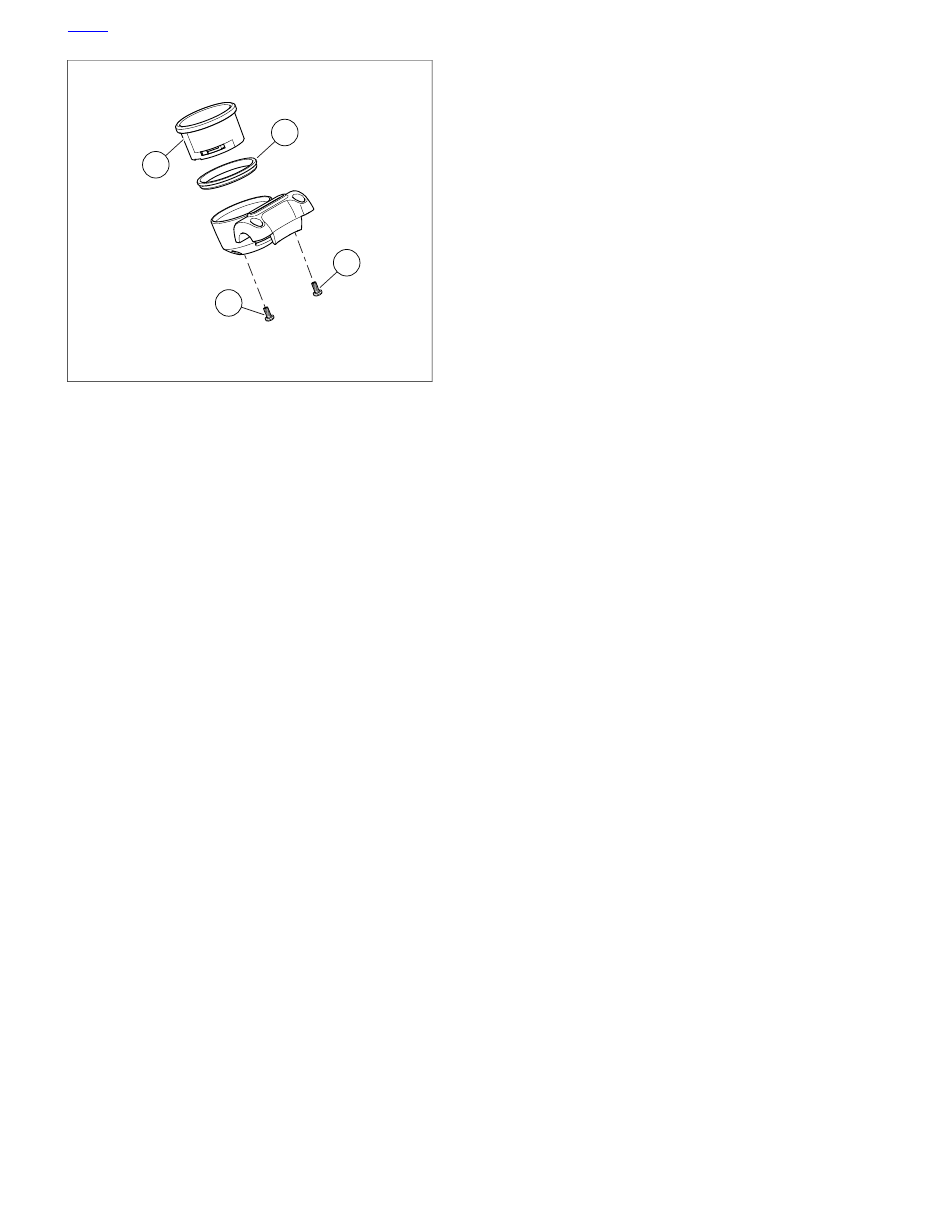
sm07850

1. Speedometer
2. Seal
3. Fastener (2)

Figure 7-87. Speedometer: FXSB

HOME

7-60 2013 Softail Service: Electrical

7.27

VEHICLE SPEED SENSOR (VSS)

GENERAL

The vehicle speed sensor is powered and monitored by the
ECM. The ECM processes the vehicle speed signal and
transmits this signal to the BCM and speedometer through
serial data.

The vehicle speed sensor is located on the transmission just
behind the transmission top cover.

REMOVAL

1.

Remove seat.

To prevent accidental vehicle start-up, which could cause
death or serious injury, remove main fuse before pro-
ceeding. (00251b)

2.

Remove main fuse.

3.

Remove rear electrical panel. See

7.3 ELECTRICAL

PANEL

.

4.

See

Figure 7-88

Disconnect 3-place vehicle speed sensor

connector [65].

5.

Remove sensor mounting bolt and lift sensor from trans-
mission case.

INSTALLATION

TORQUE VALUE

FASTENER

9.5-12.2 Nm

84-108

in-lbs

VSS mounting bolt

1.

See

Figure 7-88

. Install sensor into transmission case

using mounting bolt. Tighten bolt to 84-108

in-lbs

(9.5-

12.2 Nm).

2.

Mate 3-place vehicle speed sensor connector [65].

3.

Install electrical panel. See

7.3 ELECTRICAL PANEL

.

4.

Install main fuse.

After installing seat, pull upward on seat to be sure it is
locked in position. While riding, a loose seat can shift
causing loss of control, which could result in death or
serious injury. (00070b)

5.

Install seat.

sm02733a

Figure 7-88. Vehicle Speed Sensor

HOME

2013 Softail Service: Electrical 7-61

7.28

INDICATOR LAMPS

GENERAL

The indicator lamp assembly is equipped with Light Emitting
Diode (LED) indicators. The indicator lamp assembly is not
serviceable. If one LED is bad, the entire assembly must be
replaced.

See the electrical diagnostic manual for troubleshooting pro-
cedures.

REMOVAL: ALL BUT FXS/B

1.

Perform steps to remove fuel tank. Do not remove cros-
sover tube. See

4.6 FUEL TANK

.

2.

See

Figure 7-89

Slide fuel tank rearward and disconnect

instruments harness connector [20] (1).

3.

See

Figure 7-90

. Remove connectors (1-3).

4.

See

Figure 7-91

. Remove indicator lamp assembly.

a.

All but FLSTC, FLS:

Squeeze clips of bezel (3)

together and gently pry indicator lamp assembly (4)
out of console.

b.

FLSTC, FLS:

Remove screws (5) and gently pull

indicator lamp assembly (4) out of console.

INSTALLATION: ALL BUT FXS/B

1.

See

Figure 7-91

Attach indicator lamp assembly to con-

sole.

a.

All but FLSTC, FLS:

Make sure clips of bezel (3)

engage to secure assembly in place.

b.

FLSTC, FLS:

Install screws (5).

2.

See

Figure 7-90

. Install connectors (1-3).

3.

See

Figure 7-89

Connect instruments harness connector

[20] (1).

4.

Install fuel tank. See

4.6 FUEL TANK

.

5

4

1

2

3

6

sm07179a

1. Instruments [20]
2. Left hand control [24]
3. Fuel gauge [117]
4. Front wheel speed sensor [167]
5. Headlamp [38]
6. Front fender tip lamp [32]: FLSTC

Figure 7-89. Under Fuel Tank Left Side

1

3

2

sm07261

1. Ignition and light switch [33]
2. Speedometer (39)
3. Fuel Tank [141]

Figure 7-90. Instruments Harness Connectors

HOME

7-62 2013 Softail Service: Electrical

4

4

6

2

2

1

5

3

sm02734b

1. Console: all but FLSTC, FLS
2. Nut and washer
3. Bezel
4. Indicator lamp assembly
5. Screw (4)
6. Console: FLSTC, FLS

Figure 7-91. Indicator Lamp Assembly

REMOVAL: FXS

1.

Slide fuel tank rearward. See

4.6 FUEL TANK

.

2.

See

Figure 7-92

. Disconnect Instruments connector (1).

3.

See

Figure 7-93

. Remove fasteners (12) securing

speedometer housing (5) to upper fork bracket (9).

4.

Remove speedometer connector [39] (6) from speedo-
meter (2).

5.

Remove indicator lamp cover fasteners (3) securing
indicator lamp cover (11) to housing (5).

6.

Remove indicator lamps (8) from indicator lamp cover.

5

4

1

2

3

6

sm07179a

1. Instruments [20]
2. Left hand control [24]
3. Fuel gauge [117]
4. Front wheel speed sensor [167]
5. Headlamp [38]
6. Front fender tip lamp [32]: FLSTC

Figure 7-92. Under Fuel Tank Left Side

HOME

2013 Softail Service: Electrical 7-63

11

2

4

5

10

8

7

1

6

12

9

3

sm07180

1. Indicator lamp bezel
2. Speedometer
3. Indicator lamp cover fasteners
4. Gasket
5. Housing
6. Speedometer connector [39]
7. Speedometer fasteners
8. Indicator lamps
9. Upper fork bracket
10. Instrument connector [20]
11. Indicator lamp cover
12. Housing fasteners

Figure 7-93. Speedometer: FXS

INSTALLATION: FXS

TORQUE VALUE

FASTENER

1.7-2.1 Nm

15-19

in-lbs

Indicator lamp cover fasteners:
FXS

8.1-13.6 Nm

72-120

in-lbs

Speedometer housing
fasteners: FXS

1.

See

Figure 7-93

Install

new

Indicator lamp assembly (8)

into indicator lamp cover (11).

2.

Position indicator lamp in position under housing (5).

3.

Install indicator lamp cover fasteners and tighten to 15-19

in-lbs

(1.7-2.1 Nm).

4.

Install speedometer connector (6) to speedometer (2).

5.

Place housing in position over upper fork bracket (9).

6.

Install housing fasteners (12). Tighten fasteners to 72-120

in-lbs

(8.1-13.6 Nm).

7.

See

Figure 7-92

Connect instrument connector [20] (1)

to harness under fuel tank.

8.

Install fuel tank. See

4.6 FUEL TANK

.

9.

Test indicator lamps for proper operation.

REMOVAL: FXSB

1.

Slide fuel tank back to access instrumentation connector.
See

4.6 FUEL TANK

.

2.

Disconnect instrumentation connector.

3.

Disconnect speedometer connector.

NOTE

Support handlebar in position.

4.

See

Figure 7-94

Remove fasteners (2).

5.

Remove both screws (4) securing indicator lamp assembly
(3) to upper handlebar clamp (1).

6.

Remove indicator lamp assembly.

INSTALLATION: FXSB

TORQUE VALUE

FASTENER

2.3-3.4 Nm

20-30

in-lbs

Indicator lamp screws: FXSB

16.3-21.7 Nm

12-16 ft-lbs

Upper handlebar clamp
fasteners: FXSB

1.

See

Figure 7-94

. Attach indicator lamp assembly (3) to

upper handlebar clamp (1) with screws (4). Tighten to
20-30

in-lbs

(2.3-3.4 Nm).

NOTE

The slight gap between upper and lower handlebar clamps
should face the rider.

2.

Loosely install upper handlebar clamp (1) with fasteners
(2).

3.

See

Figure 7-95

Align marks with seam of clamps.

4.

Tighten forward fasteners then rear fasteners to 12-16 ft-
lbs (16.3-21.7 Nm).

5.

Route indicator lamp wiring to instrumentation and
speedometer connectors. Connect connectors.

6.

Install fuel tank. See

4.6 FUEL TANK

.

HOME

7-64 2013 Softail Service: Electrical

1

2

3

4

sm07852

1. Upper Handlebar clamp
2. Fasteners (4)
3. Indicator lamp assembly
4. Screw (2)

Figure 7-94. Indicator Lamp

sm07851

Figure 7-95. Alignment Marks

HOME

2013 Softail Service: Electrical 7-65

7.29

NEUTRAL SWITCH

GENERAL

See

Figure 7-96

. The neutral switch is located on the transmis-

sion top cover. The two terminal switch is normally open. When
the transmission shifter is in neutral and the ignition switch is
in the IGNITION position, the switch causes the NEUTRAL
indicator light to illuminate.

REMOVAL

1.

Remove battery and battery caddy. See

1.20 BATTERY

MAINTENANCE, Disconnection and Removal

.

2.

Make sure transmission shifter is in NEUTRAL.

3.

See

Figure 7-97

. Remove connectors from switch studs.

4.

Remove neutral switch and O-ring from transmission top
cover.

NOTE

To replace connectors, use heat-sealed butt splice connectors.
See

A.23 SEALED SPLICE CONNECTORS

.

INSTALLATION

TORQUE VALUE

FASTENER

13.6-20.3 Nm

120-180

in-lbs

Neutral switch

NOTE

The transmission shifter must be in the NEUTRAL position
when installing the switch to allow the bottom ball on the switch
to engage the ramp on the shifter cam.

1.

See

Figure 7-97

. Lubricate O-ring with transmission oil.

2.

Install switch with O-ring to transmission top cover. Tighten
to 120-180

in-lbs

(13.6-20.3 Nm).

NOTE

The neutral switch is not polarity sensitive, so either connector
can be attached to either stud.

3.

Install connectors to switch studs.

4.

Install battery caddy and battery. See

1.20 BATTERY

MAINTENANCE, Installation and Connection

.

sm02737

Figure 7-96. Neutral Switch Location

2

1

sm02738

1. O-ring
2. Switch stud

Figure 7-97. Neutral Switch

5.

Test neutral switch for proper operation.

a.

Turn ignition switch to IGNITION position.

b.

Verify that transmission shifter is in NEUTRAL.

c.

Check to see that NEUTRAL indicator light illuminates.

HOME

7-66 2013 Softail Service: Electrical

7.30

OIL PRESSURE SWITCH

GENERAL

See

Figure 7-98

The oil pressure switch monitors oil pressure

in the crankcase. If the oil pressure drops below 3 psi (20.6
kPa), the oil pressure switch is tripped and illuminates the low
oil pressure indicator light. The oil pressure switch is located
on the right side of the crankcase.

REMOVAL

1.

See

Figure 7-98

. Remove connector (2) from oil pressure

switch (1).

2.

Remove oil pressure switch from crankcase.

1

2

sm02788

1. Oil pressure switch
2. Connector jumper

Figure 7-98. Oil Pressure Switch

INSTALLATION

TORQUE VALUE

FASTENER

10.8-16.3 Nm

96-144

in-lbs

Oil pressure switch

1.

Coat threads of oil pressure switch with LOCTITE 565
THREAD SEALANT.

2.

See

Figure 7-98

. Install oil pressure switch (1) to crank-

case. Tighten to 96-144

in-lbs

(10.8-16.3 Nm).

3.

Attach connector (2) to oil pressure switch.

4.

Test oil pressure switch for proper operation.

NOTE

If connector (2) requires replacement, see

A.23 SEALED

SPLICE CONNECTORS

.

HOME

2013 Softail Service: Electrical 7-67

7.31

REAR STOP LAMP SWITCH

GENERAL

See

Figure 7-99

. The rear stop lamp switch monitors brake

fluid pressure in the rear brake line. When pressure in the line
reaches a preset level, the rear stop lamp switch is tripped and
illuminates the tail light/stop lamp.

REMOVAL

D.O.T. 4 brake fluid will damage painted and body panel
surfaces it comes in contact with. Always use caution and
protect surfaces from spills whenever brake work is per-
formed. Failure to comply can result in cosmetic damage.
(00239b)

1.

See

Figure 7-99

. Remove both connectors (2) from rear

stop lamp switch (1).

2.

Place a clean container under the rear stop lamp switch
and brake line to catch escaping fluid.

3.

Remove rear stop lamp switch.

INSTALLATION

TORQUE VALUE

FASTENER

16.3-20.3 Nm

12-15 ft-lbs

Rear stop lamp switch

1.

Coat threads of stop lamp switch with LOCTITE 565
THREAD SEALANT. Do not allow thread sealant to make
contact with end of switch.

2.

See

Figure 7-99

. Install rear stop lamp switch (1). Tighten

to 12-15 ft-lbs (16.3-20.3 Nm).

3.

Install both switch connectors (2).

After repairing the brake system, test brakes at low speed.
If brakes are not operating properly, testing at high speeds
can cause loss of control, which could result in death or
serious injury. (00289a)

4.

Bleed brake system. See

2.15 BLEEDING BRAKES

.

Be sure that all lights and switches operate properly before
operating motorcycle. Low visibility of rider can result in
death or serious injury. (00316a)

5.

Check stop lamp for proper operation.

1

2

sm02740

1. Stoplight switch
2. Connectors

Figure 7-99. Rear Stoplight Switch

HOME

7-68 2013 Softail Service: Electrical

7.32

HORN

INSPECTION

If the horn fails to sound or does not sound satisfactorily, check
for loose, frayed or damaged wires leading to horn terminal,
discharged battery or corroded ground.

The horn cannot be repaired or adjusted for tone. Only the
mounting hardware is replaceable.

REMOVAL AND INSTALLATION: ALL BUT
FXS/B

TORQUE VALUE

FASTENER

4.0-6.2 Nm

35-55

in-lbs

Horn bracket screws: All but
FXS/B

9.0-11.3 Nm

80-100

in-lbs

Horn bracket clamp: All but
FXS/B

9.0-11.3 Nm

80-100

in-lbs

Horn bracket nut: All but
FXS/B

1.

See

Figure 7-100

. Remove acorn nut (4) and washer (5)

to detach horn bracket (6) from vehicle.

2.

Disconnect wires from posts on back side of horn.

3.

Remove screws (8) and nut (10) to detach horn from
bracket. Free wires from clamp (9).

4.

Install

new

horn on bracket.

a.

Secure with screws (8), and push nuts (3). Tighten
screws to 35-55

in-lbs

(4.0-6.2 Nm).

b.

Install nut (10) and tighten to 80-100

in-lbs

(9.0-11.3

Nm). Fold wires under clamp (9).

5.

Attach wiring.

6.

Attach horn bracket to vehicle using washer (5) and acorn
nut (4). Tighten nut to 80-100

in-lbs

(9.0-11.3 Nm). When

tightening fasteners, be sure the horn does not contact
the horn cover or other parts.

7

2

9

4

5

6

8

10

1

3

sm02647

1. Horn
2. Cover
3. Push nut (2)
4. Acorn nut
5. Washer
6. Bracket
7. Rubber mount
8. Screw (2)
9. Clamp
10. Nut

Figure 7-100. Horn: All But FXS/B

HOME

2013 Softail Service: Electrical 7-69

REMOVAL AND INSTALLATION: FXS/B

TORQUE VALUE

FASTENER

17.64-20.36

Nm

13-15 ft-lbs

Horn bracket mounting bolt,
FXS/B

1.

See

Figure 7-101

. Remove bolt (3) and washer (2) to

detach horn bracket (1) from vehicle.

2.

Disconnect wires from posts on back side of horn.

3.

Remove locknut (5) to detach horn from bracket.

4.

Replace horn.

5.

Attach horn to bracket with

new

locknut (5).

6.

Attach wiring.

7.

Attach horn bracket to vehicle using washer (2) and bolt
(3). Tighten to 13-15 ft-lbs (17.64-20.36 Nm).

5

1

2

3

4

sm04125

1. Bracket
2. Washer
3. Bolt
4. Horn
5. Locknut

Figure 7-101. Horn: FXS/B

HOME

7-70 2013 Softail Service: Electrical

7.33

ACTIVE EXHAUST

GENERAL

The active exhaust system utilizes an actuator valve located
in the rear exhaust pipe which is connected to a servo motor
via a cable. The valve position automatically adjusts to enhance
engine performance.

The active exhaust module is located on the exhaust bracket.
The attached cable is routed to a bellcrank located on the rear
exhaust pipe.

REMOVAL

1.

Remove exhaust system. See

4.17 EXHAUST SYSTEM

.

2.

See

Figure 7-102

Disconnect active exhaust module

connector [179] (5).

3.

Remove active exhaust cable housing (1) from notch in
shroud (2). Remove ferrule (3) from active exhaust module
to free cable (4).

4.

See

Figure 7-103

Remove module fasteners (4) from

active exhaust module bracket (2).

3

4

1

2

5

sm02645

1. Active exhaust cable housing
2. Shroud, HDI, Australia and England only
3. Ferrule
4. Active exhaust cable
5. Active exhaust module connector [179]

Figure 7-102. Active Exhaust Module

5

1

4

3

2

sm02741

1. Interconnect tube assembly
2. Active exhaust module bracket
3. Active exhaust module
4. Fastener
5. Rear exhaust pipe

Figure 7-103. Active Exhaust Module Mounting

REPAIR

NOTE

See

Figure 7-102

Active exhaust module shroud (2) can be

replaced. Replace shroud if active exhaust cable housing (1)
is a loose fit in shroud.

1.

Remove fasteners securing shroud.

2.

Replace shroud. Replace fasteners and tighten securely.

INSTALLATION

TORQUE VALUE

FASTENER

3.6-4.5 Nm

32-40

in-lbs

Active exhaust module
fasteners

1.

See

Figure 7-103

. Install active exhaust module (3) to

bracket (2) using fasteners (4). Tighten fasteners to 32-40

in-lbs

(3.6-4.5 Nm).

2.

See

Figure 7-102

. Install ferrule (3) into slot shown. Wrap

cable around active exhaust module shroud as shown.

3.

Clip active exhaust cable housing (1) into shroud (2).

4.

Connect active exhaust module connector [179] (5).

5.

Install exhaust system. See

4.17 EXHAUST SYSTEM

.

HOME

2013 Softail Service: Electrical 7-71

7.34

MAIN WIRING HARNESS

REMOVAL

NOTES

See Appendix B for the main wiring harness schematic
and a description of all connector locations.

Disarm security system before removal.

Note position of all clamps and cable straps before removal
to aid during installation.

1.

Remove seat.

Disconnect negative (-) battery cable first. If positive (+)
cable should contact ground with negative (-) cable con-
nected, the resulting sparks can cause a battery explosion,
which could result in death or serious injury. (00049a)

2.

Disconnect battery cables, negative cable first. Remove
battery. See

7.12 BATTERY CABLES

.

3.

Remove battery caddy.

4.

Disconnect harness grounds (just forward of battery).

5.

Remove right saddlebag if present.

NOTE

Rear wheel may have to be raised slightly to allow for splash
guard removal.

6.

Remove rear splash guard to access electrical panel.

7.

Remove rear electrical panel. See

7.3 ELECTRICAL

PANEL

.

8.

Remove vehicle speed sensor connector [65] located on
transmission case.

9.

Disconnect rear oxygen sensor connector [137] located
between battery and ground terminals.

10. Remove fuel tank. See

4.6 FUEL TANK

. This includes

detaching fuel gauge connector [117] (not present on
FXS/B) and fuel pump and sender [141].

11. Remove voltage regulator and connectors located behind

regulator. See

7.23 VOLTAGE REGULATOR

.

a.

Voltage regulator [77].

b.

Stator [47].

c.

Front oxygen sensor connector [138].

d.

Crank position sensor [79].

e.

Front HCU connector [254].

f.

Jiffy stand interlock connector [133].

12. Disconnect front wheel speed sensor (WSS) [167].

13. Remove active exhaust connector [179] from active

exhaust module if equipped, or remove cable straps
securing connector to frame.

14. Remove air cleaner and disconnect active intake solenoid

connector [179]. See

4.3 AIR CLEANER ASSEMBLY

.

1

2

sm02742

1. Rubber trim
2. Push-in fastener

Figure 7-104. Rubber Trim

15. See

Figure 7-104

Remove push-in fastener (2) from

rubber trim (1) on frame. Disconnect connectors:

a.

MAP sensor connector [80].

b.

Right handlebar controls [22].

c.

Left handlebar controls [24].

d.

Instruments connector [20].

e.

Front turn signals [31].

f.

Front fender tip lamp [32] (FLSTC only).

g.

Headlamp [38].

h.

Spotlamp switch (if present).

i.

Horn wires [122].

j.

IAT sensor connector [89].

k.

ET sensor connector [90].

l.

IAC connector [87].

m. TP sensor connector [88].

n.

front and rear ACR connectors [203F, 203R], if
equipped.

o.

Front [84] and rear [85] fuel injector connectors.

HOME

7-72 2013 Softail Service: Electrical

16. Disconnect connectors:

a.

Electronic control module [78].

b.

Stop lamp switch.

c.

Oil pressure switch [121].

d.

Main harness power wire from starter stud.

e.

Starter solenoid [128].

f.

Tail lamp [7].

g.

Rear HCU connector [255].

h.

Neutral switch wiring [131].

17. Disconnect coil connector [83].

18. Slowly remove harness from frame taking note of wire

routings.

INSTALLATION

NOTE

Be sure to securely attach ground terminals to their proper
frame locations and replace all cable straps.

1.

Place harness wires into their original positions.

2.

Attach the following connectors:

a.

Neutral switch wiring [131].

b.

If equipped with ABS, rear HCU connector [255].

c.

Tail lamp [7].

d.

Starter solenoid [128].

e.

Main harness power wire from starter stud.

f.

Oil pressure switch [121].

g.

Stop lamp switch.

h.

Electronic control module [78].

3.

Attach connectors under fuel tank trim.

a.

front and rear ACR connectors [203F, 203R], if
equipped.

b.

Front [84] and rear [85] fuel injector connectors.

c.

TP sensor connector [88].

d.

IAC connector [87].

e.

ET sensor connector [90].

f.

IAT sensor connector [89].

g.

Horn wires.

h.

Spotlamp switch (if present).

i.

Headlamp [38].

j.

Front fender tip lamp [32] (FLSTC only).

k.

Front turn signals [31].

l.

Instruments connector [20].

m. Left handlebar controls [24].

n.

Right handlebar controls [22].

o.

MAP sensor connector [80].

4.

See

Figure 7-104

. Install push-in fastener (2) to rubber

trim (1) on frame.

5.

Connect active intake solenoid connector [179] and install
air cleaner. See

4.3 AIR CLEANER ASSEMBLY

.

6.

Connect active exhaust connector [179] to active exhaust
module, if equipped. Or secure connector to frame with
cable straps.

7.

If equipped with ABS, connect front wheel speed sensor
(WSS) [167] and secure wire with clips and cable straps.
See

C.4 WHEEL SPEED SENSORS, Front Wheel Speed

Sensor

.

8.

Install voltage regulator and connectors located behind
regulator. See

7.23 VOLTAGE REGULATOR

.

a.

Jiffy stand interlock connector [133].

b.

If equipped with ABS, connect front HCU connector
[254].

c.

Crank position sensor [79].

d.

Front oxygen sensor connector [138].

e.

Stator [47].

f.

Voltage regulator [77].

9.

Install fuel tank. This includes attaching fuel gauge con-
nector [117] and fuel pump and sender [141]. See

4.6 FUEL TANK

.

10. Connect connectors and install instrument console. See

7.26 SPEEDOMETER

.

a.

Ignition key switch [33].

b.

Indicator lamp connector [21].

c.

Speedometer connector [39].

11. Install vehicle speed sensor (VSS) connector [65]. VSS

is located on the transmission case.

12. Install electrical panel, connectors and splash guard. See

7.3 ELECTRICAL PANEL

.

a.

If equipped with ABS, ECU [166].

b.

Purge solenoid [95].

c.

Security siren [142].

d.

BCM [242].

e.

If equipped with ABS, rear wheel speed sensor [168].

f.

FXSB:

ECM

13. See

Figure 7-105

. Attach connectors under seat.

a.

Secure main fuse connector (4) in cover.

b.

Secure data link connector [91A] to frame.

c.

Rear oxygen sensor connector [137].

d.

All But FXSB: ECM.

HOME

2013 Softail Service: Electrical 7-73

1

2

3

5

6

4

sm02744b

1. Tail lamp connector [7]
2. ECM [78-1] (all but FXSB)
3. ECM [78-2] (all but FXSB)
4. Data link connector [91A]
5. Main fuse connector [64]
6. Rear O2 sensor connector [137]

Figure 7-105. Connectors Under Seat

2

1

sm02745b

1. Ground wires (2)
2. Ground wire and negative battery cable

Figure 7-106. Ground Wires and Negative Battery Cable

14. See

Figure 7-106

Attach ground wires to frame in front

of battery. Negative battery cable attaches to right side
post (2). See

7.12 BATTERY CABLES

.

Connect positive (+) battery cable first. If positive (+) cable
should contact ground with negative (-) cable connected,
the resulting sparks can cause a battery explosion, which
could result in death or serious injury. (00068a)

15. Install battery caddy, battery, and connect battery cables,

positive cable first. See

7.12 BATTERY CABLES

.

16. Install right saddlebag, if removed.

After installing seat, pull upward on seat to be sure it is
locked in position. While riding, a loose seat can shift
causing loss of control, which could result in death or
serious injury. (00070b)

17. Install seat.

Be sure that all lights and switches operate properly before
operating motorcycle. Low visibility of rider can result in
death or serious injury. (00316a)

18. Turn ignition ON. Test switches for correct operation.

a.

Left and right turn signals, front and rear.

b.

Four-way hazard warning flashers.

c.

Rear brake lamp.

d.

Headlamp.

e.

Horn.

f.

Indicator lamps.

g.

Starter.

h.

Speedometer.

HOME

7-74 2013 Softail Service: Electrical

7.35

HANDLEBAR CONTROL MODULES

GENERAL

The handlebar switches are now modular and are of rugged
construction and feature a superior seal to protect electrical
contacts and components from dirt and moisture in harsh
environments.

The left hand control module includes headlamp HI - LO, horn,
trip, and left turn signal functions. The right hand control module
includes engine start, RUN - OFF, right turn signal, and flasher
functions. The left and right hand control modules are non-
repairable.

NOTES

On certain models, the turn signal wiring is hard wired to
the hand control modules.

To replace the right or left hand control modules, see

7.36 RIGHT HANDLEBAR CONTROL MODULE

or

7.37 LEFT HANDLEBAR CONTROL MODULE

.

REPAIR PROCEDURES

TOOL NAME

PART NUMBER

ROBINAIR HEAT GUN

HD-25070

ULTRA TORCH UT-100

HD-39969

HEAT SHIELD ATTACHMENT

HD-41183

1.

Push conduit back to better access wires and avoid dam-
aging conduit with radiant heating device. Secure conduit
with extra 7.0 in (177.8 mm) cable strap in kit.

2.

Strip 0.5 in (12.7 mm) of insulation off switch wires. Twist
stripped ends of switch wires until all strands are tightly
coiled.

3.

Cut dual wall heat shrink tubing, supplied in repair kit into
1.0 in (25.4 mm) segments. Slide tubing over each wire
of

new

switch assembly.

4.

Splice existing and

new

switch wires, matching wire colors.

Solder the spliced connections. For best results, splice
one wire at a time.

5.

Center the heat shrink tubing over the soldered splices.

Be sure to follow manufacturer's instructions when using
the UltraTorch UT-100 or any other radiant heating device.
Failure to follow manufacturer's instructions can cause a
fire, which could result in death or serious injury. (00335a)

Avoid directing heat toward any fuel system component.
Extreme heat can cause fuel ignition/explosion resulting
in death or serious injury.

Avoid directing heat toward any electrical system com-
ponent other than the connectors on which heat shrink
work is being performed.

Always keep hands away from tool tip area and heat shrink
attachment.

6.

See

Figure 7-107

. Use ULTRA TORCH UT-100 (Part

No. HD-39969) or ROBINAIR HEAT GUN (Part No. HD-
25070) with HEAT SHIELD ATTACHMENT (Part No. HD-
41183) or equivalent. Uniformly heat the heat shrink tubing
to insulate and seal the soldered connections. Apply heat
just until the meltable sealant exudes out both ends of
tubing and assumes a smooth cylindrical appearance.

7.

Inspect solder connection.

a.

Inspect the melted sealant for solder beads.

b.

Excess solder or heat may force some solder out with
the melted sealant.

c.

Remove any solder found.

d.

Briefly heat the connection to reseal the tubing if
solder beads were removed.

e.

Use less solder or reduce heating time or intensity
when doing subsequent splices.

Be sure that all lights and switches operate properly before
operating motorcycle. Low visibility of rider can result in
death or serious injury. (00316a)

3

2

1

sm00082

1. Ultra Torch UT-100
2. Robinair Heat Gun
3. Heat Shield Attachment

Figure 7-107. Radiant Heating Devices

HOME

2013 Softail Service: Electrical 7-75


Content      ..     26      27      28      29     ..