Harley Davidson Softail Delux FLSTN BIKE 2011-2015. Electrical Diagnostics - page 16
HOME
3. Is continuity present?
DTC P2300
a. Yes. Repair short to ground in (GN/BE) wire.
PART NUMBER
TOOL NAME
b. No. Replace ECM.
HD-41404
HARNESS CONNECTOR TEST KIT
DTC P2301
HD-50390-1
BREAKOUT BOX
HD-50390-4
ECM CABLE
PART NUMBER
TOOL NAME
HD-50390-4-P
ECM OVERLAY
HD-41404
HARNESS CONNECTOR TEST KIT
Table 6-72. DTC P2300 Diagnostic Faults
Table 6-73. DTC P2301 Diagnostic Faults
POSSIBLE CAUSES
POSSIBLE CAUSES
Ignition coil malfunction
Ignition coil malfunction
Open or short to ground in signal circuit
Short to voltage in signal circuit
Open power circuit
1. Ignition Coil Shorted to Voltage Test
1. Ignition Coil Test
1. Turn IGN OFF.
1. Turn IGN OFF.
2. Disconnect ignition coil [83].
2. Disconnect ignition coil [83].
3. Turn IGN ON.
3. Using HARNESS CONNECTOR TEST KIT (Part No. HD-
4. Using HARNESS CONNECTOR TEST KIT (Part No. HD-
41404), test resistance between [83A] terminals A and D.
41404), test voltage between [83B] terminal D (GN/BE)
4. Is resistance greater than 2 Ohms?
wire and ground.
a. Yes. Replace ignition coil.
5. Is voltage greater than 5.0V?
b. No. Go to Test 2.
a. Yes. Repair short to voltage in (GN/BE) wire.
b. No. Go to Test 2.
2. Input Voltage Test
1. Turn IGN ON.
2. Open Test
2. Test voltage between [83B] terminal A (R/GN) wire and
1. Test resistance between [83A] terminals A and D.
ground.
2. Is resistance greater than 0.4 Ohms?
3. Is battery voltage present?
a. Yes. Replace ECM.
a. Yes. Go to Test 3.
b. No. Replace ignition coil.
b. No. Repair open on (R/GN) wire.
DTC P2303
3. Control Wire Continuity Test
1. Turn IGN OFF.
PART NUMBER
TOOL NAME
HD-41404
HARNESS CONNECTOR TEST KIT
2. Connect BREAKOUT BOX (Part No. HD-50390-1) and
ECM CABLE (Part No. HD-50390-4) between wiring har-
HD-50390-1
BREAKOUT BOX
ness [78B-1] and [78B-2] and ECM [78A-1] and [78A-2].
HD-50390-4
ECM CABLE
See 1.2 DIAGNOSTIC TOOLS.
HD-50390-4-P
ECM OVERLAY
3. Verify ECM OVERLAY (Part No. HD-50390-4-P) is in
position on BOB.
Table 6-74. DTC P2303 Diagnostic Faults
4. Test continuity between BOB [78-1] terminal 2 and [83B]
terminal D (GN/BE) wire.
POSSIBLE CAUSES
5. Is continuity present?
Ignition coil malfunction
a. Yes. Go to Test 4.
Open or short to ground in signal circuit
b. No. Repair open in (GN/BE) wire.
Open power circuit
4. Control Wire Shorted to Ground Test
1. Ignition Coil Test
1. Disconnect [78A-1] and [78A-2].
1. Turn IGN OFF.
2. Test continuity between BOB [78-1] terminal 2 and ground.
2. Disconnect ignition coil [83].
6-88 2013 Softail Diagnostics: Engine Management
HOME
3. Using HARNESS CONNECTOR TEST KIT (Part No. HD-
3. Is continuity present?
41404), test resistance between [83A] terminals A and C.
a. Yes. Repair short to ground in (GY/BE) wire.
4. Is resistance greater than 2 Ohms?
b. No. Replace ECM.
a. Yes. Replace ignition coil.
DTC P2304
b. No. Go to Test 2.
PART NUMBER
TOOL NAME
2. Input Voltage Test
HD-41404
HARNESS CONNECTOR TEST KIT
1. Turn IGN ON.
2. Test voltage between [83B] terminal A (R/GN) wire and
ground.
Table 6-75. DTC P2304 Diagnostic Faults
3. Is battery voltage present?
POSSIBLE CAUSES
a. Yes. Go to Test 3.
Ignition coil malfunction
b. No. Repair open in (R/GN) wire.
Short to voltage in signal circuit
3. Control Wire Continuity Test
1. Ignition Coil Shorted to Voltage Test
1. Turn IGN OFF.
1. Turn IGN OFF.
2. Connect BREAKOUT BOX (Part No. HD-50390-1) and
2. Disconnect ignition coil [83].
ECM CABLE (Part No. HD-50390-4) between wiring har-
3. Turn IGN ON.
ness [78B-1] and [78B-2] and to ECM [78A-1] and [78A-
2]. See 1.2 DIAGNOSTIC TOOLS.
4. Using HARNESS CONNECTOR TEST KIT (Part No. HD-
41404), test voltage between [83B] terminal C (GY/BE)
3. Verify ECM OVERLAY (Part No. HD-50390-4-P) is in
wire and ground.
position on BOB.
5. Is voltage more than 5.0V?
4. Test continuity between BOB [78-1] terminal 1 and [83B]
a. Yes. Repair short to voltage in (GY/BE) wire.
terminal C (GY/BE) wire.
b. No. Go to Test 2.
5. Is continuity present?
a. Yes. Go to Test 4.
2. Open Test
b. No. Repair open in (GY/BE) wire.
1. Test resistance between [83A] terminals A and C.
4. Control Wire Shorted to Ground Test
2. Is resistance greater than 0.4 Ohms?
1. Disconnect [78A-1] and [78A-2].
a. Yes. Replace ECM.
2. Test continuity between BOB [78-1] terminal 1 and ground.
b. No. Replace ignition coil.
2013 Softail Diagnostics: Engine Management 6-89
HOME
ENGINE CRANKS,
BUT WILL NOT START
6.26
DESCRIPTION AND OPERATION
ENGINE CRANKS BUT WILL NOT START
If the starter will not crank the engine, the problem is not EFI
PART NUMBER
TOOL NAME
related. See 3.2 STARTING SYSTEM or 5.11 SECURITY
SYSTEM.
HD-26792
SPARK TESTER
There may be DTCs associated with this problem. Check for
HD-41404
HARNESS CONNECTOR TEST KIT
DTCs and clear them before proceeding with this test.
HD-50390-1
BREAKOUT BOX
NOTE
HD-50390-2
BCM CABLE
To set a CKP DTC, a start attempt must last at least five
HD-50390-2-P
BCM OVERLAY
seconds.
ed02012
Table 6-76. Engine Cranks But Will Not Start Diagnostic
Faults
POSSIBLE CAUSES
Battery voltage too low
Ignition system issues
Fuel system issues
Electrical system issues
No or low compression
Open ground circuit
1. Preliminary Engine Tests
1. Verify battery connections are in good condition.
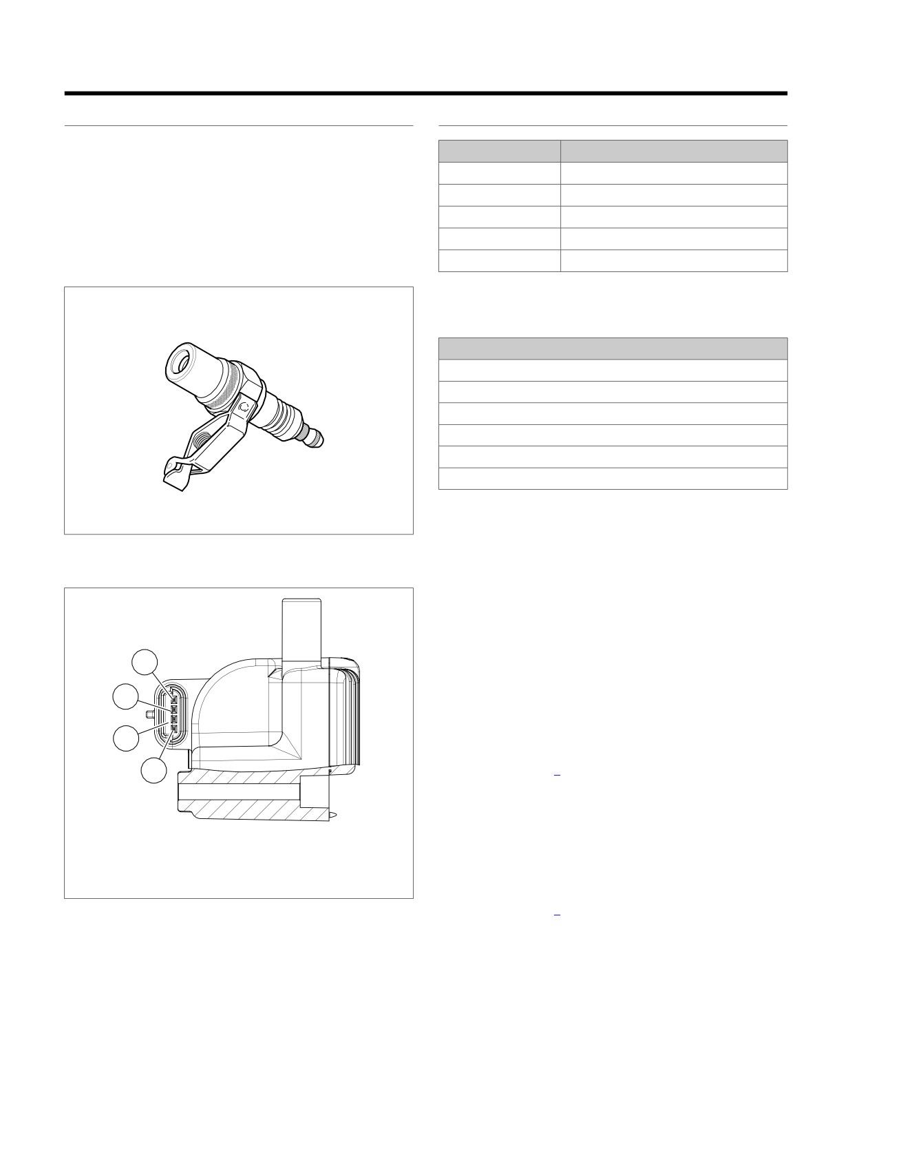
Figure 6-57. Spark Tester
2. Verify there are no blown fuses.
3. Verify fuel in the tank is fresh and not contaminated.
ed02980
4. Verify spark plug wires are firmly connected the coil and
plugs.
5. Verify fuel injectors are not clogged.
4
6. Check for DTCs. See 2.1 INITIAL DIAGNOSTICS, Odo-
meter Self-Diagnostics. If DTCs are present, see the
3
appropriate DTC procedure.
7. Verify battery condition. See 3.1 BATTERY TESTING.
2
8. Does battery pass tests?
1
a. Yes. Go to Test 2.
b. No. Charge or replace battery.
2. Check Engine Lamp Test
1.
Terminal A: power
1. Turn IGN ON and engine stop switch to RUN.
2.
Terminal B: ion sense
3.
Terminal C: rear coil
2. Does check engine lamp illuminate for 4 seconds immedi-
4.
Terminal D: front coil
ately after key ON?
a. Yes. Go to Test 3.
Figure 6-58. Ignition Coil: Typical
b. No. Verify all fuses are good. See 2.1 INITIAL DIA-
GNOSTICS, Initial Diagnostics.
3. Spark Present Test
1. Check spark plug condition and replace if fouled.
2. Using SPARK TESTER (Part No. HD-26792), check spark
at both plugs while cranking engine.
6-90 2013 Softail Diagnostics: Engine Management
HOME
3. Is spark present?
6. Fuel System Test
a. Yes. Go to Test 4.
1. Check fuel system and perform fuel pressure test.
b. No. The spark plugs will not spark if there is low or
2. Does fuel pressure meet specification?
no compression. If spark is not present, test compres-
a. Yes. Inspect and clean throttle body and repair as
sion before troubleshooting ignition circuit. Once good
needed.
compression is confirmed, check condition of ignition
coils, coil primary wiring and spark plug boots. See
b. No. Inspect fuel inlet sock and fuel filter for obstruc-
6.12 DTC P0371, P0372, P0374 or 6.20 DTC P1353,
tion. Inspect internal fuel hose for leaks. If no issues
P1356.
are found, replace fuel pump assembly.
4. Compression Test
7. Fuel Pump Open Circuit Test
1. Perform compression test.
1. Turn IGN OFF.
2. Does engine pass compression test?
2. Connect BREAKOUT BOX (Part No. HD-50390-1) and
a. Yes. Go to Test 5.
BCM CABLE (Part No. HD-50390-2) between wire harness
[242B], leaving
[242A] disconnected. See
1.2 DIA-
b. No. Repair engine loss of compression.
GNOSTIC TOOLS.
5. Fuel Pump Voltage Test
3. Verify BCM OVERLAY (Part No. HD-50390-2-P) is in
position on BOB.
1. Disconnect fuel pump connector [141].
4. Using HARNESS CONNECTOR TEST KIT (Part No. HD-
2. Using HARNESS CONNECTOR TEST KIT (Part No. HD-
41404) and a multimeter, test for continuity between [141B]
41404) and a multimeter, measure voltage between fuel
terminal A and system relay BOB terminal F4.
pump [141B] terminals A and D during the first 2-3 seconds
after IGN ON.
5. Is continuity present?
a. Yes. Repair open on (BK) wire to ground.
3. Is battery voltage present?
a. Yes. Go to Test 6.
b. No. Repair open (R/BN) wire.
b. No. Go to Test 7.
2013 Softail Diagnostics: Engine Management 6-91
HOME
HESITATION, LOSS OF POWER
6.27
DESCRIPTION AND OPERATION
Connector Information
Improper fuel system pressure may contribute to hesitation,
For additional information about the connectors in the following
loss of power.
diagram(s) and diagnostic procedure(s), including the color of
the harness test kit terminal probes, see B.1 CONNECTORS.
ed03326
1
2
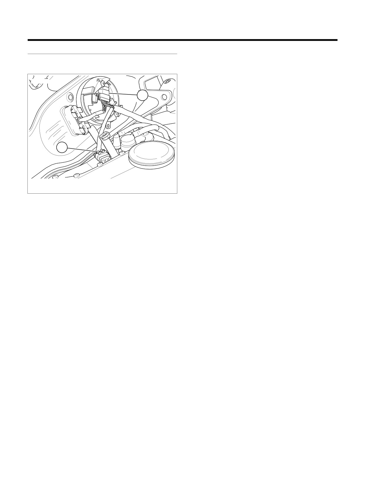
1. Speedometer [39]
2. Fuel pump [141]
Figure 6-59. Under Console: FXDB/BP/FXDL
6-92 2013 Softail Diagnostics: Engine Management
HOME
em01349
BCM
Main
R
Harness
1
F4
J3
[242A]
Battery
F4
J3
[242B]
15A
2
[64B]
BE
Main Harness
[20A] [20B]
Fuel Pump
BK
8
8
BK
[141B] [141A]
And
Sender
R/BN
7
7
R/BN
R/O
6
6
R/O
R/BN
A
A
Fuel Pump Power
W/Y
4
4
W/Y
W/Y
B
B
Fuel Level Sender
BK/GN
2
2
BK/GN
BK/GN
C
C
Sender Ground
BK
D
D
Pump Ground
[39B] [39A]
R/O
5
5
Battery Fuse
BK/GN
9
9
Fuel Level
W/Y
7
7
Ground
Speedometer
[117B] [117A]
Fuel
Gauge
BE
1
1
O
Running Light Power
W/Y
2
2
Y
Fuel Level Sender
BK/GN
4
4
BK
Ground
GND 2
GND 1
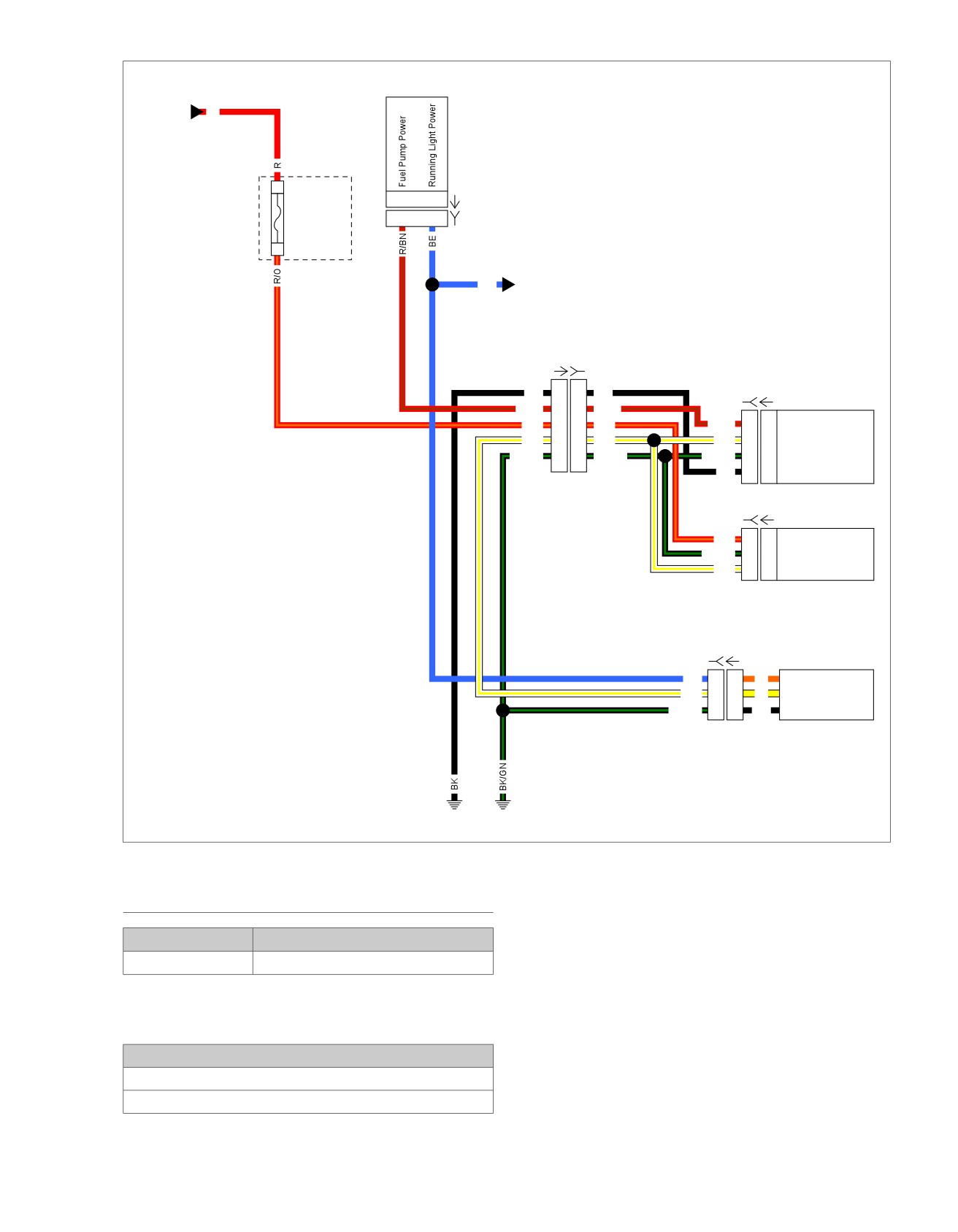
Figure 6-60. Fuel Sensor Circuit
HESITATION, LOSS OF POWER TEST
1. Preliminary Engine Tests
1. Verify battery connections are in good condition.
PART NUMBER
TOOL NAME
2. Verify there are no blown fuses.
HD-26792
SPARK TESTER
3. Verify fuel in the tank is fresh and not contaminated.
4. Verify spark plug wires are firmly connected the coil and
Table 6-77. Hesitation, Loss of Power Test Diagnostic
plugs.
Faults
5. Verify fuel injectors are not clogged.
POSSIBLE CAUSES
6. Check for DTCs. See 2.1 INITIAL DIAGNOSTICS, Odo-
Loss of engine compression
meter Self-Diagnostics. If DTCs are present, see the
Fuel system issues
appropriate DTC procedure.
2013 Softail Diagnostics: Engine Management 6-93
HOME
7. Verify battery condition. See 3.1 BATTERY TESTING.
3. Is spark present?
a. Yes. Go to Test 4.
8. Does battery pass tests?
a. Yes. Go to Test 2.
b. No. The spark plugs will not spark if there is low or
no compression. If spark is not present, test compres-
b. No. Charge or replace battery.
sion before troubleshooting ignition circuit. Once good
compression is confirmed, check condition of ignition
2. Vacuum Leak Test
coils, coil primary wiring and spark plug boots. See
1. Start the motorcycle and check for vacuum leaks.
6.12 DTC P0371, P0372, P0374 or 6.20 DTC P1353,
P1356.
2. Were any leaks found?
a. Yes. Repair the vacuum leak.
4. Compression Test
b. No. Go to Test 3.
1. Perform compression test.
2. Does engine pass compression test?
3. Spark Present Test
a. Yes. Go to Test 5.
1. Check spark plug condition and replace if fouled.
b. No. Repair engine loss of compression.
2. Using SPARK TESTER (Part No. HD-26792), check spark
at both plugs while cranking engine.
5. Fuel System Test
1. Check fuel system and perform fuel pressure test.
2. Does fuel pressure meet specification?
a. Yes. Inspect and clean throttle body and repair as
needed.
b. No. Inspect fuel inlet sock and fuel filter for obstruc-
tion. Inspect internal fuel hose for leaks. If no issues
are found, replace fuel pump assembly.
6-94 2013 Softail Diagnostics: Engine Management
HOME
STARTS, THEN STALLS
6.28
DESCRIPTION AND OPERATION
Diagnostic Tips
The starts, then stalls condition may be created by the fuel
•
The vehicle will stall if the jiffy stand is extended when the
system, the idle air control system or an ECM failure.
transmission is in gear.
There may be DTCs set causing this condition. Solve the
•
If this condition is fuel related, perform fuel pressure test.
problems with the DTCs before performing the tests in this
Connector Information
section. The DTCs that may be involved with starts, then stalls
are:
For additional information about the connectors in the following
diagram(s) and diagnostic procedure(s), including the color of
•
Fuel injectors: DTCs P0261, P0262, P0263 and P0264
the harness test kit terminal probes, see B.1 CONNECTORS.
•
Password problem: DTC P1009
•
TPS: DTCs P0122 and P0123
•
ECM errors: DTCs P0603 and P0605
•
IAC errors: DTCs P0506 and P0507
2013 Softail Diagnostics: Engine Management 6-95
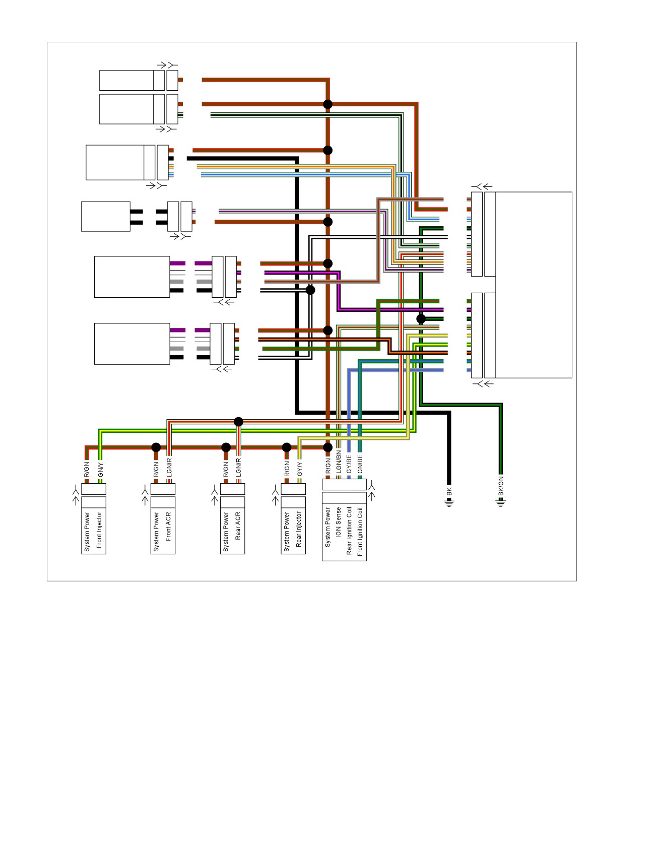
HOME
em00997
[242A] [242B]
BCM
System Power
L3
L3
R/GN
Purge
System Power
A
A
R/GN
Solenoid
Purge Solenoid
B
B
LGN/BK
[95A] [95B]
System Power
1
1
R/GN
Active
Ground
2
2
BK
Exhaust
Exhaust Actuator
3
3
LGN/O
Exhaust Feedback
4
4
LGN/BE
[78B-2] [78A-2]
ECM
[179A] [179B]
GY/BN
17
17
Rear HO2 Sensor
Active
Active Intake
BK
2
2
LGN/V
R/GN
16
16
System Power
Intake
LGN/BE
14
14
Exhaust Feedback
System Power
BK
1
1
R/GN
BK/GN
10
10
Ground
BK/W
7
7
5V Sensor Ground
[178A] [178B]
LGN/BK
5
5
Purge Solenoid
LGN/R
4
4
ACR Enable
System Power
V
1
1
R/GN
LGN/O
3
3
Exhaust Actuator
Rear HO2
Rear O2 Heater Ground
W
2
2
BK/PK
LGN/V
2
2
Active Intake
Sensor
Rear O2 Sensor
GY
3
3
GY/BN
5V Sensor Ground
BK
4
4
BK/W
LGN/BN
17
17
Front HO2 Sensor
[138B] [138A]
BK/PK
15
15
Rear HO2 Heater Sensor
BK/GN
10
10
Ground
LGN/BN
9
9
ION Sense
System Power
V
1
1
R/GN
GY/Y
6
6
Rear Fuel Injector
Front HO2
Front O2 Heater Ground
W
2
2
BK/O
GN/Y
5
5
Front Fuel Injector
Sensor
Front O2 Sensor
GY
3
3
GN/BN
BK/O
3
3
Front HO2 Heater Ground
5V Sensor Ground
BK
4
4
BK/W
GN/BE
2
2
Front Ignition Coil
GY/BE
1
1
Rear Ignition Coil
[138B] [138A]
[78B-1] [78A-1]
A B C D
[83B]
[84B]
A B
[203FB]
A B
[203RB]
A B
[85B]
A B
A B C D
[83A]
[84A]
A B
[203FA]
A B
[203RA]
A B
[85A]
A B
GND 2
GND 1
Front Fuel
Front ACR
Rear ACR
Rear Fuel
Injector
Injector
Ignition Coil
Figure 6-61. System Power Circuit
6-96 2013 Softail Diagnostics: Engine Management
HOME
2. Is fuel pressure normal?
STARTS, THEN STALLS
a. Yes. If fuel injectors are okay, then continue with
PART NUMBER
TOOL NAME
tests. Go to Test 3.
HD-41404
HARNESS CONNECTOR TEST KIT
b. No. Repair fuel pressure problem.
HD-50390-1
BREAKOUT BOX
3. System Power Test
HD-50390-4
ECM CABLE
1. Turn IGN OFF.
HD-50390-4-P
ECM OVERLAY
2. Connect BREAKOUT BOX (Part No. HD-50390-1) and
ECM CABLE (Part No. HD-50390-4) to wiring harness
Table 6-78. Starts, Then Stalls Diagnostic Faults
[78B-1] and [78B-2], leaving ECM [78A-1] and [78A-2]
disconnected. See 1.2 DIAGNOSTIC TOOLS.
POSSIBLE CAUSES
3. Verify ECM OVERLAY (Part No. HD-50390-4-P) is in
Fuel system malfunction
position on BOB.
Idle air control system malfunction
4. Turn IGN ON.
1. Throttle Test
5. Using HARNESS CONNECTOR TEST KIT (Part No. HD-
1. Will engine start with the throttle partially opened and then
41404), test voltage between BOB [78-2] terminal 16 and
stall when closed?
ground.
a. Yes. See 6.15 DTC P0506, P0507 and perform IAC
6. Is voltage present?
diagnostic procedure.
a. Yes. Inspect connections at ECM. See 1.3 DIA-
b. No. Go to Test 2.
GNOSTICS AND TROUBLESHOOTING, Wiggle Test.
If connections are good and wiggle test does not find
2. Fuel System Test
intermittent, replace the ECM.
1. Perform fuel pressure test.
b. No. Repair open in (R/GN) wire.
2013 Softail Diagnostics: Engine Management 6-97
HOME
MISFIRE AT IDLE OR UNDER LOAD
6.29
DESCRIPTION AND OPERATION
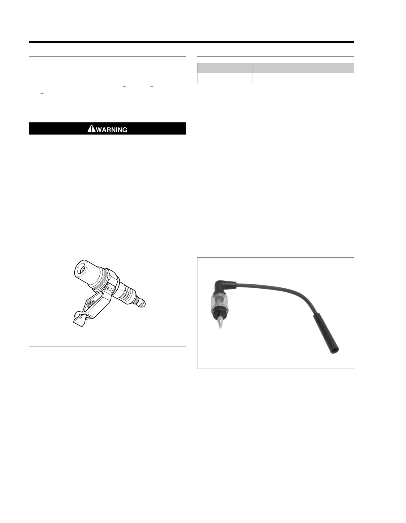
IN-LINE SPARK TESTER
Misfire conditions may be caused by:
PART NUMBER
TOOL NAME
•
Battery condition and connections.
YA840
SNAP-ON IN-LINE SPARK TESTER
•
Fuel system problems. Refer to Table 6-1, Table 6-2 and
Table 6-3.
See Figure 6-63. Using a SNAP-ON IN-LINE SPARK TESTER
(Part No. YA840) or equivalent can help determine whether a
•
Ignition system faults.
problem exists in the ignition or fuel systems.
Diagnostic Tips
•
If the test light flashes without interruption on both cylinders
during the misfire event, verify spark plug condition and
gap and inspect the fuel system for proper operation.
Wipe up spilled fuel and dispose of rags in a suitable
•
If the test light does not flash or the flash is interrupted
manner. An open spark around gasoline could cause a
during the misfire event, the problem is ignition related.
fire or explosion, resulting in death or serious injury.
1. Turn IGN OFF.
(00518b)
2. Remove front spark plug wire and install SNAP-ON IN-
•
When performing the steps in the diagnostic tests, use a
LINE SPARK TESTER (Part No. YA840) between spark
known good part to verify whether a suspected part is
plug wire and spark plug.
faulty.
3. Start engine and inspect tester light. The light will flash on
•
The ignition coil does not require full installation to be
each spark event if power is transmitted to the plug.
functional.
4. Install and repeat procedure on rear cylinder.
•
Verify faulty ignition coil by performing resistance test. See
6.20 DTC P1353, P1356.
NOTE
Use a SNAP-ON IN-LINE SPARK TESTER (Part No. YA840)
ed02012
and a load applying dynamometer to diagnose misfire under
load.
ed01780
Figure 6-62. Spark Tester
Figure 6-63. In-line Spark Tester
Connector Information
For additional information about the connectors in the following
diagram(s) and diagnostic procedure(s), including the color of
the harness test kit terminal probes, see B.1 CONNECTORS.
6-98 2013 Softail Diagnostics: Engine Management
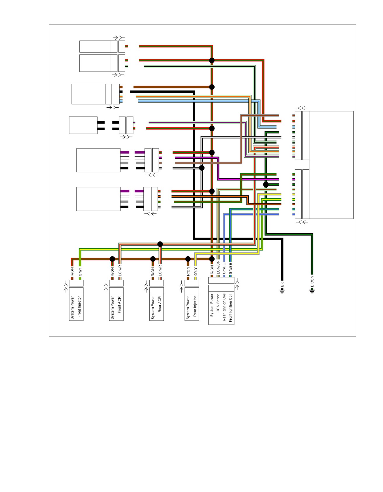
HOME
em00997
[242A] [242B]
BCM
System Power
L3
L3
R/GN
Purge
System Power
A
A
R/GN
Solenoid
Purge Solenoid
B
B
LGN/BK
[95A] [95B]
System Power
1
1
R/GN
Active
Ground
2
2
BK
Exhaust
Exhaust Actuator
3
3
LGN/O
Exhaust Feedback
4
4
LGN/BE
[78B-2] [78A-2]
ECM
[179A] [179B]
GY/BN
17
17
Rear HO2 Sensor
Active
Active Intake
BK
2
2
LGN/V
R/GN
16
16
System Power
Intake
LGN/BE
14
14
Exhaust Feedback
System Power
BK
1
1
R/GN
BK/GN
10
10
Ground
BK/W
7
7
5V Sensor Ground
[178A] [178B]
LGN/BK
5
5
Purge Solenoid
LGN/R
4
4
ACR Enable
System Power
V
1
1
R/GN
LGN/O
3
3
Exhaust Actuator
Rear HO2
Rear O2 Heater Ground
W
2
2
BK/PK
LGN/V
2
2
Active Intake
Sensor
Rear O2 Sensor
GY
3
3
GY/BN
5V Sensor Ground
BK
4
4
BK/W
LGN/BN
17
17
Front HO2 Sensor
[138B] [138A]
BK/PK
15
15
Rear HO2 Heater Sensor
BK/GN
10
10
Ground
LGN/BN
9
9
ION Sense
System Power
V
1
1
R/GN
GY/Y
6
6
Rear Fuel Injector
Front HO2
Front O2 Heater Ground
W
2
2
BK/O
GN/Y
5
5
Front Fuel Injector
Sensor
Front O2 Sensor
GY
3
3
GN/BN
BK/O
3
3
Front HO2 Heater Ground
5V Sensor Ground
BK
4
4
BK/W
GN/BE
2
2
Front Ignition Coil
GY/BE
1
1
Rear Ignition Coil
[138B] [138A]
[78B-1] [78A-1]
A B C D
[83B]
[84B]
A B
[203FB]
A B
[203RB]
A B
[85B]
A B
A B C D
[83A]
[84A]
A B
[203FA]
A B
[203RA]
A B
[85A]
A B
GND 2
GND 1
Front Fuel
Front ACR
Rear ACR
Rear Fuel
Injector
Injector
Ignition Coil
Figure 6-64. System Power Circuit
2013 Softail Diagnostics: Engine Management 6-99
HOME
4. Did spark jump gap on both cables?
MISFIRE AT IDLE OR UNDER LOAD
a. Yes. Check for faulty, worn or cracked spark plugs,
PART NUMBER
TOOL NAME
plug fouling due to mechanical problems or faulty
connection at plug or coils. Repair as required.
HD-26792
SPARK TESTER
b. No. Go to Test 3.
HD-41404
HARNESS CONNECTOR TEST KIT
HD-50390-1
BREAKOUT BOX
3. Spark Plug Wire Test
HD-50390-4
ECM CABLE
1. Turn IGN OFF.
HD-50390-4-P
ECM OVERLAY
2. Disconnect spark plug cables.
3. Test resistance of both spark plug cables.
Table 6-79. Misfire At Idle or Under Load Diagnostic Faults
4. Is resistance within specifications? Refer to Table 1-5.
POSSIBLE CAUSES
a. Yes. Go to Test 4.
Ignition system malfunction
b. No. Replace out of range spark plug cable.
Fuel system malfunction
4. Carbon Tracking Inspection Test
IAC malfunction
Electrical system malfunction
1. Inspect top of ignition coils for carbon tracking.
2. Is carbon tracking present?
1. Power Ground Continuity Test
a. Yes. Replace ignition coil.
1. Turn IGN OFF.
b. No. Switch ignition coil with known good unit and
2. Connect BREAKOUT BOX (Part No. HD-50390-1) and
perform previous test. If spark jumps gap, replace
ECM CABLE (Part No. HD-50390-4) between wiring har-
ignition coil. If not, then continue with tests. Go to
ness [78B-1], [78B-2] and to ECM [78A-1] and [78A-2].
Test 5.
See 1.2 DIAGNOSTIC TOOLS.
3. Verify ECM OVERLAY (Part No. HD-50390-4-P) is in
5. Ignition Coil Primary Wire Continuity Test
position on BOB.
1. Disconnect ignition coil [83].
4. Using HARNESS CONNECTOR TEST KIT (Part No. HD-
2. Disconnect BCM [242].
41404), test continuity between BOB [78-1] terminal 10
3. Test resistance between [242B] terminal L3 and [83B]
and then [78-2] terminal 10 to ground.
terminal A (R/GN) wire. Wiggle connectors while meas-
5. Is continuity present?
uring.
a. Yes. Go to Test 2.
4. Is resistance continuously less than 0.5 Ohms?
b. No. Repair open on (BK/GN) wire.
a. Yes. Go to Test 6.
b. No. Repair intermittent on (R/GN) wire.
2. Spark Test
1. Connect SPARK TESTER (Part No. HD-26792) between
6. Battery to Main Fuse Block Voltage Drop
front spark plug cable and ground. See 1.2 DIAGNOSTIC
Test
TOOLS.
1. Start engine.
2. Crank engine for a few seconds.
2. Measure voltage drop between battery (+) and main fuse
3. Remove tester from front spark plug cable. Connect rear
[64B] terminal A (R) wire.
spark plug cable and ground.
3. Is voltage drop more than 1.0V?
a. Yes. Repair (R) wire between terminal A of [64B] and
connection at battery including connections at starter.
b. No. Check for corrosion or damage at BCM [259].
6-100 2013 Softail Diagnostics: Engine Management
TABLE OF CONTENTS
SUBJECT
PAGE NO.
7.1 ANTI-LOCK BRAKE SYSTEM (ABS) GENERAL INFORMATION
7-1
7.2 DTC C1018, C1041, C1042, C1044, C1224, C1225
7-4
7.3 DTC C1021, C1023
7-9
7.4 DTC C1025, C1032, C1206
7-12
7.5 DTC C1027, C1034, C1208
7-15
7.6 DTC C1052, C1102
7-19
7.7 DTC C1055
7-22
7.8 DTC C1094
7-25
7.9 DTC C1151, C1153
7-28
7.10 DTC C1158, C1178, C1184
7-30
7.11 DTC C1192, C1193
7-32
7.12 DTC C1212
7-35
7.13 DTC C1561, C1562, C1563, C1564, C1565
7-38
7.14 DTC C1567, C1568, C1571, C1572, C1573
7-41
7.15 ABS INDICATOR ALWAYS ON OR INOPERATIVE
7-45
NOTES
HOME
ANTI-LOCK BRAKE SYSTEM (ABS) GENERAL
INFORMATION
7.1
DESCRIPTION AND OPERATION
ed03311
PART NUMBER
TOOL NAME
1
HD-48650
DIGITAL TECHNICIAN II
The ABS module Electronic Control Unit (ECU) controls brake
application under extreme stopping conditions.The ABS system
is activated when wheel slip is detected. When wheel slip is
not detected, brake operation is no different than non-ABS
systems.
4
2
The ABS consists of the following components:
3
•
See Figure 7-1 and Figure 7-6. The ABS ECU module.
•
See Figure 7-2. The front HCU which contains a pump,
accumulator, solenoids, apply and release valves.
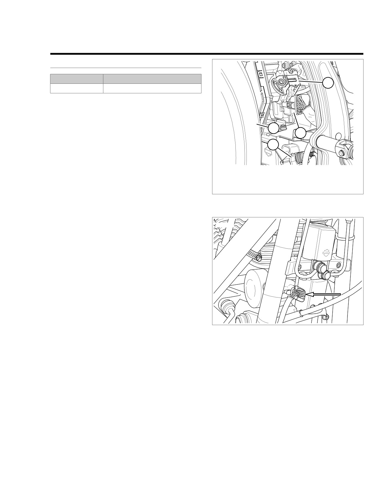
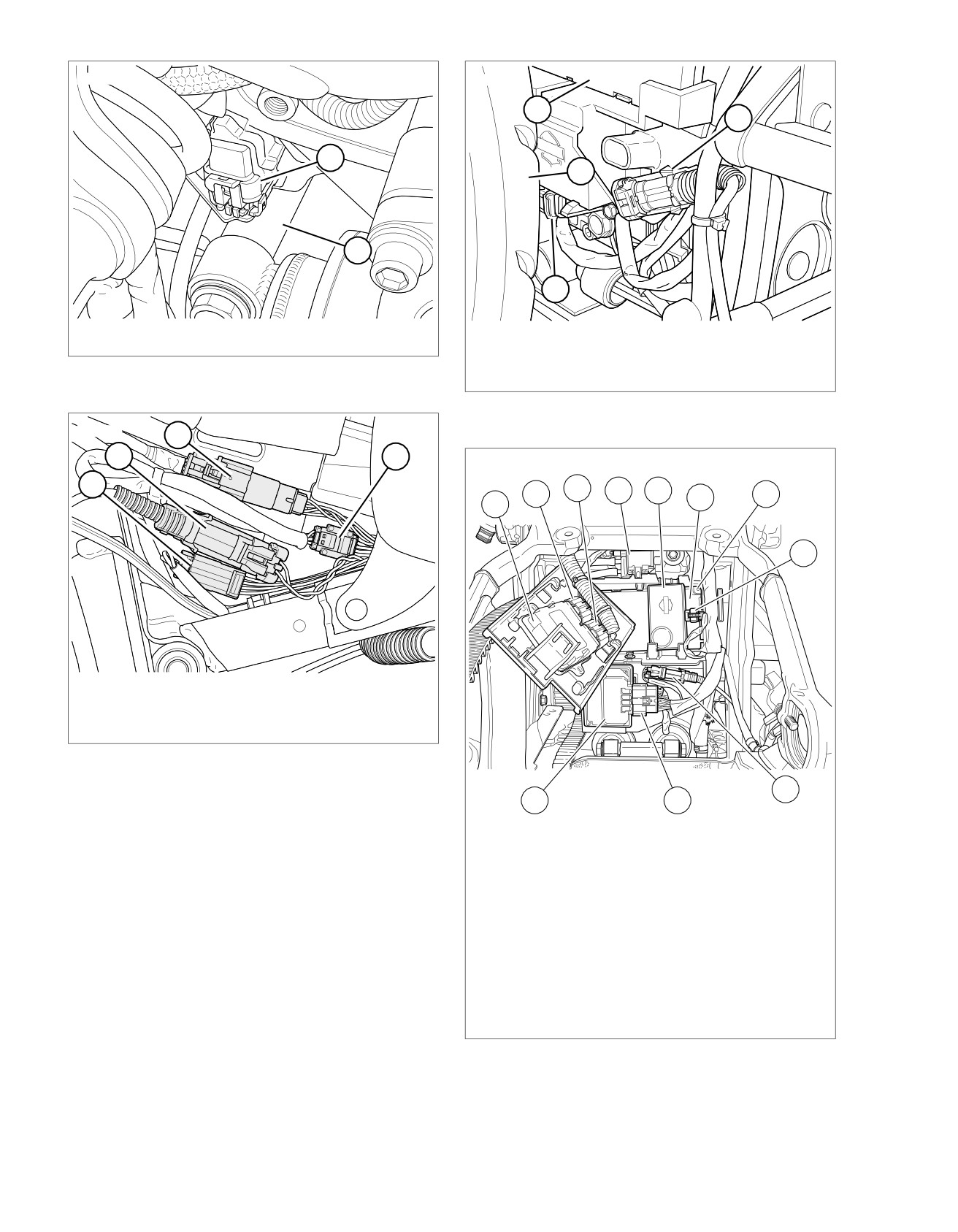
1. BCM [242]
•
See Figure 7-3. The rear HCU which contains a pump,
2. ABS ECU [166]
accumulator, solenoids, apply and release valves.
3. Rear WSS [168]
4. Rear tire
•
See Figure 7-4. Front WSS.
Figure 7-1. ABS [166]: Except FXSB
•
See Figure 7-5 and Figure 7-6. Rear WSS.
The ABS ECU responds to WSS inputs. The ABS ECU then
controls the two HCUs. When one or both of the HCU units
ed03291
are activated, the solenoid valves decrease, hold or increase
hydraulic fluid pressure to control the individual calipers of each
wheel to prevent wheel slipping. However, the HCUs cannot
increase hydraulic pressure beyond the pressure or force being
applied to the brake pedal or lever by the rider.
ABS CAN Communication Functionality
The Right Hand Control Module (RHCM) has a front brake
switch that supplies an applied signal on the CAN bus. This
CAN communication signal is sent to the ABS ECU to indicate
that the front brake is applied. The rear brake switch supplies
a ground input to the BCM. The BCM sends a rear brake
applied CAN communication signal to the ABS ECU.
Normal operation of the ABS system:
•
A series of rapid HCU solenoid valve pulsations may be
Figure 7-2. Front HCU [254]
felt in either the front brake lever or rear brake pedal but
only during initialization and anti-lock braking.
•
A ticking or popping noise may be heard as the HCU
solenoid valves cycle rapidly.
•
During anti-lock braking on dry pavement, intermittent
chirping noises may be heard as the tires approach slip-
ping.
•
A normal ABS event must also see a front or rear brake
switch or front brake switch CAN communication input to
maximize performance, but an ABS event can still occur
if no brake switch input is received based on WSS inputs.
Program replaced ABS ECUs with DIGITAL TECHNICIAN II
(Part No. HD-48650).
2013 Softail Diagnostics: ABS 7-1
HOME
ed03306
ed03309
1
2
1
4
2
3
1. Rear HCU [255]
1. BCM
2. Rear fork
2. Rear WSS [168]
3. Security siren [142]
Figure 7-3. Rear HCU [255]
4. Rear tire
Figure 7-5. BCM: Except FXSB
ed03294
3
2
4
ed03462
1
3
2
4
5
7
6
1
8
1. Head lamp [38]
2. Front WSS [167]
3. Instruments [20]
4. Left hand control [24]
Figure 7-4. Under Fuel Tank Left Side
9
11
10
1. ECM
2. ECM [78-2]
3. ECM [78-1]
4. Purge solenoid [95] (back side of purge
solenoid)
5. Security siren
6. BCM
7. BCM [242] (back side of BCM)
8. Security siren [142]
9. Rear WSS [168]
10. ABS [166]
11. ABS ECU
Figure 7-6. Electrical Panel: FXSB
7-2 2013 Softail Diagnostics: ABS
HOME
Pressure Hold
ABS Indicator
The ABS ECU commands the appropriate HCU release and
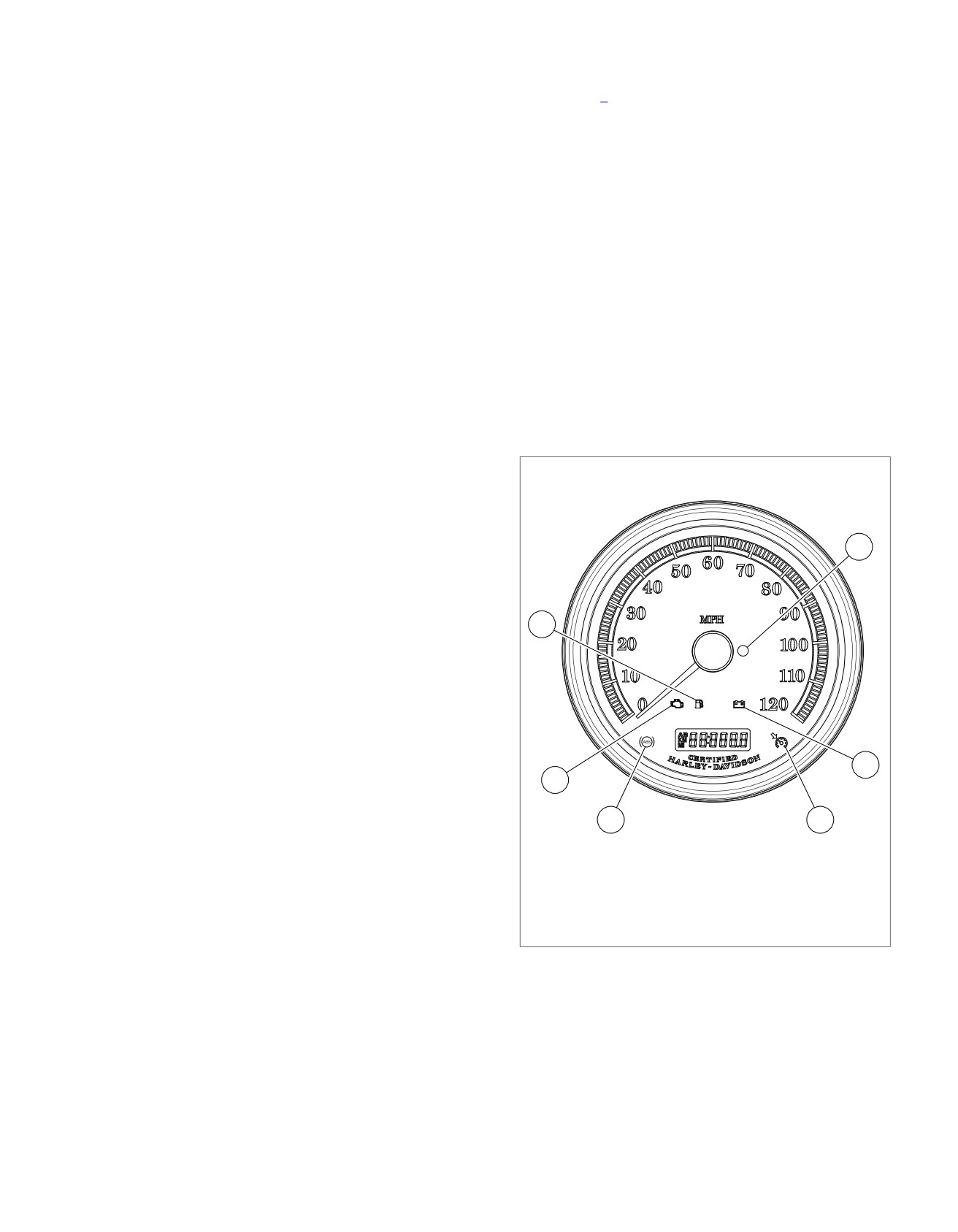
See Figure 7-7. The speedometer illuminates the ABS indicator
apply circuits to close the HCU valves. This holds the same
when the following occurs.
constant pressure on the appropriate caliper as long as the
•
The ABS ECU detects an ABS disabling malfunction. The
current hydraulic pressure is the most effective pressure to
ABS ECU sends a serial data message to the instrument
stop the vehicle in the shortest amount of time without wheel
requesting illumination.
slip.
•
The speedometer performs a bulb check.
Pressure Decrease
•
The speedometer detects a loss of communication with
Sometimes the pressure being applied to the caliper is high
the ABS ECU.
enough for the ABS ECU to detect wheel slip. To control the
wheel slip, the ABS ECU commands the appropriate HCU
•
The ABS light may flash when the IGN is turned on. This
release circuit to open the release valve and the apply circuit
will continue until the vehicle is driven to verify WSS
to close the apply valve. This releases pressure on the appro-
operation.
priate caliper until wheel slip is no longer detected. The excess
The ABS ECU sends a message to the instrument when a
fluid is stored in the accumulator, until the pump can return the
malfunction that disables ABS operation is detected. Depending
fluid to the master cylinder or fluid reservoir.
on the fault, the ABS indicator may stay on even after the
malfunction is corrected. The indicator will not go off until the
Pressure Increase
vehicle is operated at speeds greater than 10 mph (16 km/h).
After the wheel slip is corrected during an ABS event, a pres-
It is important to verify that this is not the cause of an ABS
sure increase occurs.The ABS ECU commands the appropriate
indicator, which is illuminated when no DTCs are set, before
HCU release circuit to close the release valve and the apply
attempting to diagnose other possible causes.
circuit to open the apply valve. This increases the pressure
applied to the caliper during deceleration in order to reduce
ed03268
the speed of the wheel. The increased pressure will not exceed
the pressure being applied to the master cylinder by the rider.
Initialization Self-Test
4
The ABS ECU module performs one initialization test each
ignition cycle. An ignition cycle consists of starting the vehicle
after a complete shutdown with no CAN bus communication
for more than 30 seconds. Clearing the DTCs will also reset
the ignition cycle. The ABS ECU verifies CAN communication,
3
internal circuitry and the WSS circuits.
As part of the initialization self-test, the ABS module also does
a modulator test. This test consists of energizing the actuators
and commanding the motor and solenoids on and off. The ABS
ECU will run this test the first time the vehicle speed exceeds
5 mph (8 km/h) in an ignition cycle, or when all the following
conditions are met for the first time in an ignition cycle:
5
•
Brake is not applied.
2
•
Engine is above 1000 rpm.
•
No ABS event present.
1
6
•
The ABS ECU is enabled.
1.
ABS lamp (if equipped)
•
The ABS system is not communicating with DIGITAL
2.
Check engine lamp
TECHNICIAN II (Part No. HD-48650).
3.
Low fuel lamp
4.
Security lamp
5.
Battery
6.
Cruise enabled lamp (not used)
Figure 7-7. Indicator Lamps
2013 Softail Diagnostics: ABS 7-3
HOME
DTC
C1018, C1041, C1042, C1044, C1224, C1225
7.2
DESCRIPTION AND OPERATION
ed03462
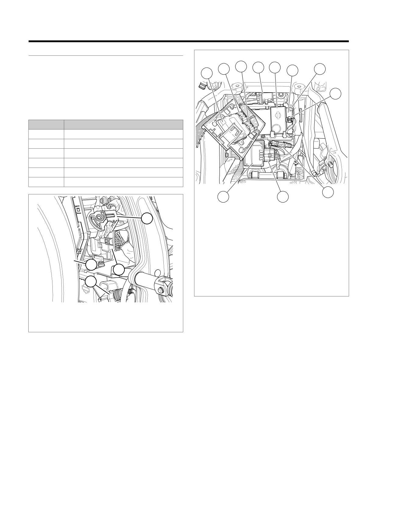
See Figure 7-8, Figure 7-9, Figure 7-10 and Figure 7-11. The
3
4
5
ABS ECU monitors the power and ground circuits of the front
2
6
7
1
and rear HCU through terminals B and D. These circuits supply
the power and ground to the pump motor in the HCU. The ABS
ECU controls the pump by turning on and off the power circuit
8
to the pump motor.
Table 7-1. Code Description
DTC
DESCRIPTION
C1018
Front actuator circuit low/open
C1041
Rear actuator circuit low/open
C1042
Front actuator circuit open
C1044
Rear actuator circuit open
C1224
Front HCU power shorted high
C1225
Rear HCU power shorted high
9
11
10
ed03311
1.
ECM
1
2.
ECM [78-2]
3.
ECM [78-1]
4.
Purge solenoid [95] (back side of purge
solenoid)
5.
Security siren
6.
BCM
4
7.
BCM [242] (back side of BCM)
2
8.
Security siren [142]
9.
Rear WSS [168]
3
10. ABS [166]
11. ABS ECU
Figure 7-9. Electrical Panel: FXSB
1. BCM [242]
2. ABS ECU [166]
3. Rear WSS [168]
Conditions for Setting the DTC
4. Rear tire
These DTCs can set if one of the following conditions exists
Figure 7-8. ABS [166]: Except FXSB
in the HCU power or ground circuit:
•
Open or high resistance on the HCU ground circuit.
•
HCU fault or malfunction.
•
ABS ECU fault or malfunction.
•
Open or high resistance on the HCU power circuit.
7-4 2013 Softail Diagnostics: ABS
HOME
ed03291
ed03306
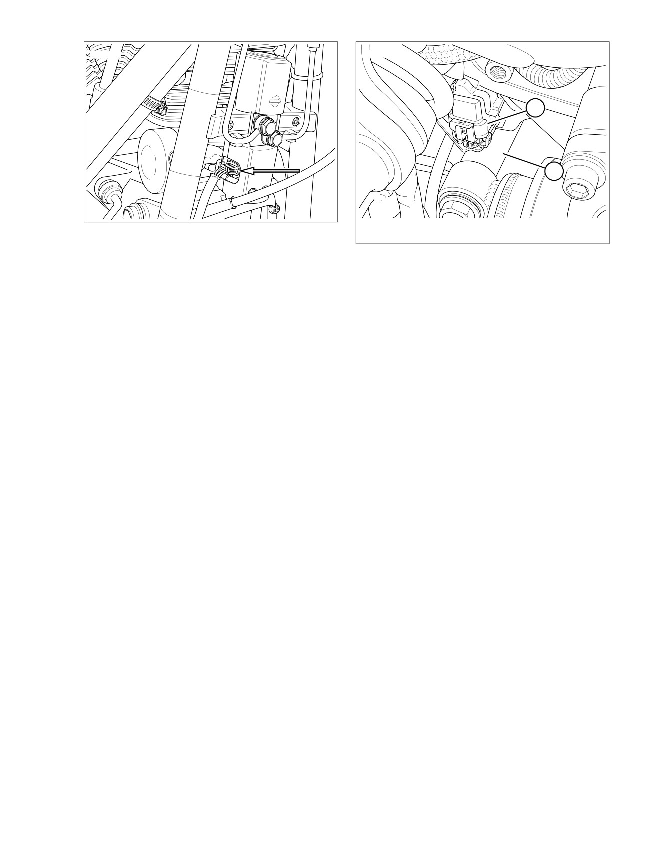
1
2
1. Rear HCU [255]
Figure 7-10. Front HCU [254]
2. Rear fork
Figure 7-11. Rear HCU [255]
Action Taken When the DTC Sets
•
ABS is disabled.
•
The ABS indicator is illuminated.
Diagnostic Tips
These DTCs are related to terminals B and D of the HCU,
either internally in the ABS ECU or HCU or externally in the
wiring or connectors. If a DTC is intermittent, it may be a con-
nection problem at the HCU, the ABS ECU or GND 2.
Connector Information
For additional information about the connectors in the following
diagram(s) and diagnostic procedure(s), including the color of
the harness test kit terminal probes, see B.1 CONNECTORS.
2013 Softail Diagnostics: ABS 7-5