Harley Davidson Softail Delux FLSTN BIKE 2011-2015. Electrical Diagnostics - page 14
HOME
2. Is resistance less than 0.5 Ohm?
5. Output Test
a. Yes. Go to Test 4.
1. Connect CKP sensor [79].
b. No. Repair open on (BK) wire.
2. Test AC voltage between BOB [78-1] terminals 16 and
18.
4. Signal Wire Shorted to CKP Ground Wire
3. Crank engine for 5 seconds while observing multimeter.
Test
4. Is AC voltage greater than 2V?
1. Test continuity between BOB [78-1] terminals 16 and 18.
a. Yes. See diagnostic tips. If MAP and IAT sensors are
2. Is continuity present?
good, replace the ECM.
a. Yes. Repair short between [79B] terminals 1 (R) and
b. No. Replace CKP sensor.
2 (BK).
b. No. Go to Test 5.
6-48 2013 Softail Diagnostics: Engine Management
HOME
DTC P0444,
P0445
6.13
DESCRIPTION AND OPERATION
ed03462
Purge Solenoid (CA and Select Foreign
3
4
5
2
6
7
Market Models Only)
1
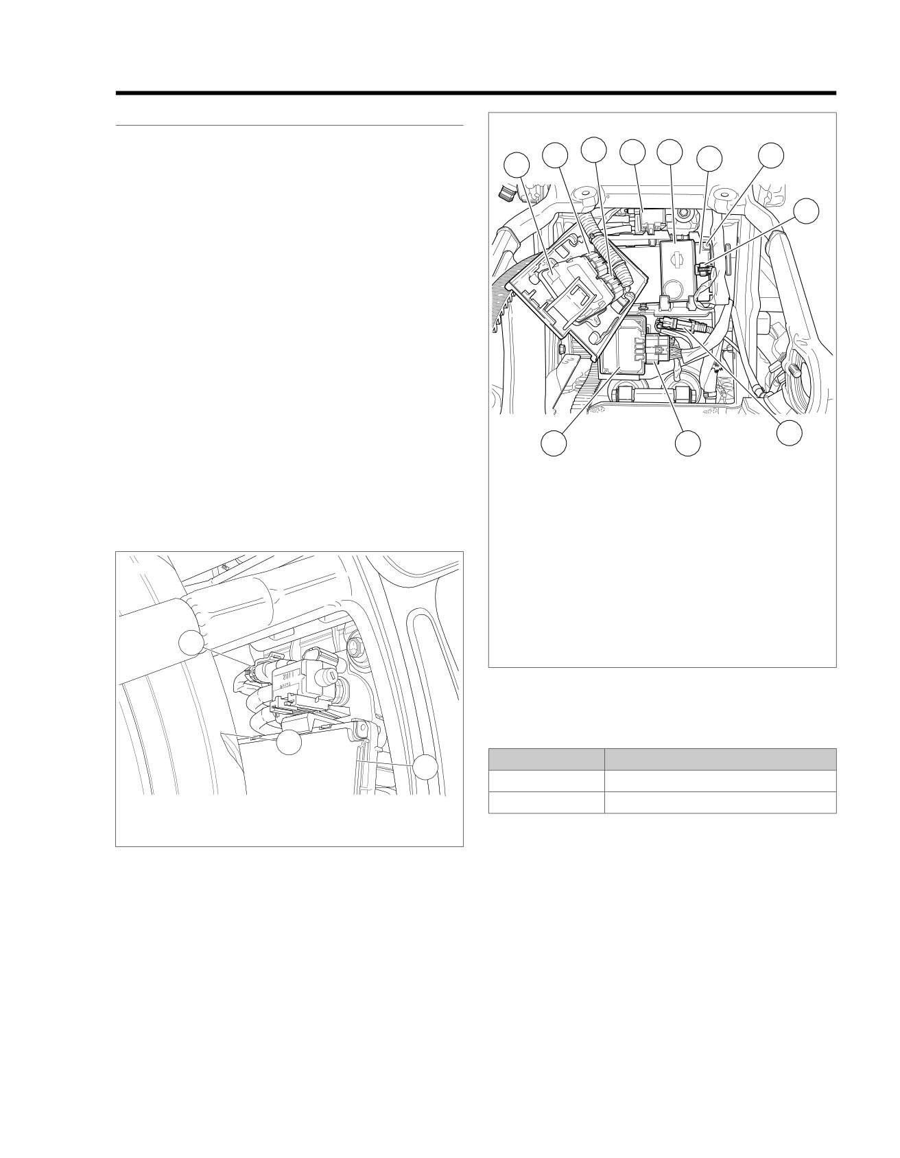
See Figure 6-24 and Figure 6-25. The purge solenoid is
mounted in front of the rear tire above the BCM. The solenoid
8
connects to a fuel tank vent line and a vent canister.
A return line from the canister reconnects to the air intake
manifold allowing vented fumes to be recirculated, for emission
efficiency. The purge solenoid is timed to the throttle position
and is disabled during startup, low engine temperature, low
engine speed or low vehicle speed.
Power for the purge solenoid is supplied by the BCM. The BCM
also provides power for the VSS, fuel injectors, active exhaust,
active intake, ECM and the ignition coil.
The ECM provides a path to ground to trigger the purge
solenoid.
NOTES
9
•
BCM or wiring harness problems will cause 12V power to
11
10
be lost to the VSS, fuel injectors, active exhaust, active
intake, ECM, ignition coil and purge solenoid.
1.
ECM
•
Purge solenoid is not installed on non-emission vehicles
2.
ECM [78-2]
and DTCs P0444 and P0445 are not available. If these
3.
ECM [78-1]
DTCs appear, the ECM should be reprogrammed.
4.
Purge solenoid [95] (back side of purge
solenoid)
ed03308
5.
Security siren
6.
BCM
7.
BCM [242] (back side of BCM)
8.
Security siren [142]
9.
Rear WSS [168]
1
10. ABS [166]
11. ABS ECU
Figure 6-25. Electrical Panel: FXSB
Table 6-41. Code Description
3
DTC
DESCRIPTION
2
P0444
Purge solenoid low/open
P0445
Purge solenoid shorted high
1. Purge valve [95]
2. BCM
Diagnostic Tips
3. Rear tire
When disconnecting any connectors always inspect connector
Figure 6-24. Purge Valve [95]: Except FXSB
for corrosion or backed out terminals and repair as required.
Connector Information
For additional information about the connectors in the following
diagram(s) and diagnostic procedure(s), including the color of
the harness test kit terminal probes, see B.1 CONNECTORS.
2013 Softail Diagnostics: Engine Management 6-49
HOME
em00997
[242A] [242B]
BCM
System Power
L3
L3
R/GN
Purge
System Power
A
A
R/GN
Solenoid
Purge Solenoid
B
B
LGN/BK
[95A] [95B]
System Power
1
1
R/GN
Active
Ground
2
2
BK
Exhaust
Exhaust Actuator
3
3
LGN/O
Exhaust Feedback
4
4
LGN/BE
[78B-2] [78A-2]
ECM
[179A] [179B]
GY/BN
17
17
Rear HO2 Sensor
Active
Active Intake
BK
2
2
LGN/V
R/GN
16
16
System Power
Intake
LGN/BE
14
14
Exhaust Feedback
System Power
BK
1
1
R/GN
BK/GN
10
10
Ground
BK/W
7
7
5V Sensor Ground
[178A] [178B]
LGN/BK
5
5
Purge Solenoid
LGN/R
4
4
ACR Enable
System Power
V
1
1
R/GN
LGN/O
3
3
Exhaust Actuator
Rear HO2
Rear O2 Heater Ground
W
2
2
BK/PK
LGN/V
2
2
Active Intake
Sensor
Rear O2 Sensor
GY
3
3
GY/BN
5V Sensor Ground
BK
4
4
BK/W
LGN/BN
17
17
Front HO2 Sensor
[138B] [138A]
BK/PK
15
15
Rear HO2 Heater Sensor
BK/GN
10
10
Ground
LGN/BN
9
9
ION Sense
System Power
V
1
1
R/GN
GY/Y
6
6
Rear Fuel Injector
Front HO2
Front O2 Heater Ground
W
2
2
BK/O
GN/Y
5
5
Front Fuel Injector
Sensor
Front O2 Sensor
GY
3
3
GN/BN
BK/O
3
3
Front HO2 Heater Ground
5V Sensor Ground
BK
4
4
BK/W
GN/BE
2
2
Front Ignition Coil
GY/BE
1
1
Rear Ignition Coil
[138B] [138A]
[78B-1] [78A-1]
A B C D
[83B]
[84B]
A B
[203FB]
A B
[203RB]
A B
[85B]
A B
A B C D
[83A]
[84A]
A B
[203FA]
A B
[203RA]
A B
[85A]
A B
GND 2
GND 1
Front Fuel
Front ACR
Rear ACR
Rear Fuel
Injector
Injector
Ignition Coil
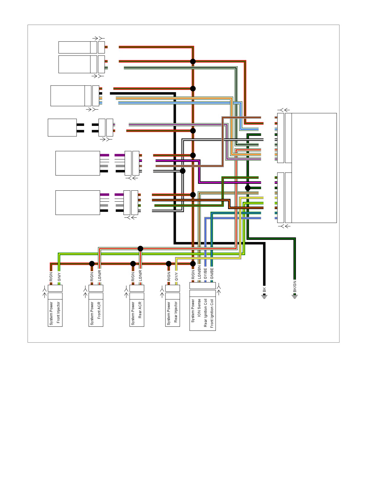
Figure 6-26. System Power Circuit
6-50 2013 Softail Diagnostics: Engine Management

HOME
2. Verify ECM OVERLAY (Part No. HD-50390-4-P) is in
DTC P0444
position on BOB.
PART NUMBER
TOOL NAME
3. Test continuity between [95B] terminal B (LGN/BK) wire
and BOB [78-2] terminal 5.
HD-41404
HARNESS CONNECTOR TEST KIT
HD-50390-1
BREAKOUT BOX
4. Is continuity present?
a. Yes. Replace ECM.
HD-50390-2-P
BCM OVERLAY
HD-50390-4
ECM CABLE
b. No. Repair open in (LGN/BK) wire.
HD-50390-4-P
ECM OVERLAY
5. Power Wire Open Test
1. Connect BREAKOUT BOX (Part No. HD-50390-1) and
Table 6-42. DTC P0444 Diagnostic Faults
ECM CABLE (Part No. HD-50390-4) to wiring harness
[78B-1] and [78B-2], leaving ECM [78A-1] and [78A-2]
POSSIBLE CAUSES
disconnected. See 1.2 DIAGNOSTIC TOOLS.
Purge solenoid malfunction
2. Verify BCM OVERLAY (Part No. HD-50390-2-P) is in
Short to ground in signal circuit
position on breakout box.
1. Purge Solenoid Test
3. Test continuity between [95B] terminal A (R/GN) wire and
BOB terminal 16.
1. Turn IGN OFF.
4. Is continuity present?
2. Disconnect purge solenoid [95].
a. Yes. Replace ECM.
3. Using HARNESS CONNECTOR TEST KIT (Part No. HD-
b. No. Repair open in (R/GN) wire.
41404), test resistance between [95A] terminals A (R/GN)
wire and B (LGN/BK) wire.
DTC P0445
4. Is resistance between 4-21 Ohms?
a. Yes. Go to Test 2.
PART NUMBER
TOOL NAME
b. No. Replace purge solenoid.
HD-41404
HARNESS CONNECTOR TEST KIT
2. Purge Solenoid Voltage Test
Table 6-43. DTC P0445 Diagnostic Faults
1. Test voltage between [95B] terminal A (R/GN) wire and
ground.
POSSIBLE CAUSES
2. Turn IGN ON.
Purge solenoid malfunction
Short to voltage in signal circuit
3. Is battery voltage present?
a. Yes. Go to Test 3.
1. Purge Solenoid Test
b. No. Go to Test 5.
1. Turn IGN OFF.
3. Control Wire Shorted to Ground Test
2. Disconnect purge solenoid [95].
1. Turn IGN OFF.
3. Using HARNESS CONNECTOR TEST KIT (Part No. HD-
41404), test resistance between [95A] terminals A (R/GN)
2. Disconnect ECM [78-1] and [78-2].
wire and B (LGN/BK) wire.
3. Test continuity between [95B] terminal B (LGN/BK) wire
4. Is resistance between 4-21 Ohms?
and ground.
a. Yes. Go to Test 2.
4. Is continuity present?
b. No. Replace purge solenoid.
a. Yes. Repair short to ground on (LGN/BK) wire.
b. No. Go to Test 4.
2. Purge Solenoid Short to Voltage Test
1. Turn IGN ON.
4. Control Wire Open Test
2. Test voltage between [95B] terminal B (LGN/BK) wire and
1. Connect BREAKOUT BOX (Part No. HD-50390-1) and
ground.
ECM CABLE (Part No. HD-50390-4) to wiring harness
[78B-1] and [78B-2], leaving ECM [78A-1] and [78A-2]
3. Is voltage greater than 5.0V?
disconnected. See 1.2 DIAGNOSTIC TOOLS.
a. Yes. Repair short to voltage on (LGN/BK) wire.
b. No. Replace ECM.
2013 Softail Diagnostics: Engine Management 6-51
HOME
DTC P0502,
P0503
6.14
DESCRIPTION AND OPERATION
ed03304
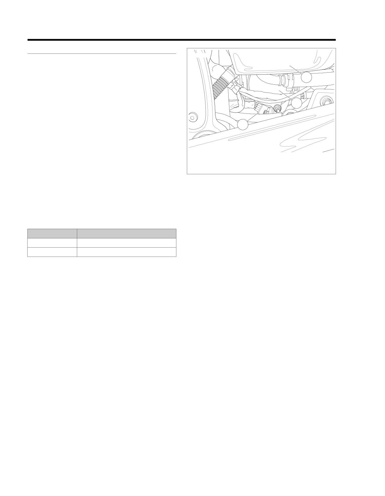
See Figure 6-27. The VSS is powered and monitored by the
ECM. The ECM processes the vehicle speed signal and
transmits this signal to the BCM and the speedometer through
2
the CAN bus circuit.
NOTES
•
The ECM uses VSS input to calculate idle air control
3
position. Therefore problems with the vehicle speed signal
can lead to improper operation of the idle air control.
•
The MAP, JSS, TPS and VSS sensors are connected to
1
the same reference line (+5V REF). If the reference line
goes to ground or open, multiple codes will be set (DTC
P0107, P0108, P0122, P0123, P0502, P0503, P1501,
P1502). Start with the trouble code having the lowest
ranking value.
1. VSS
2. Oil tank
•
A faulty sensor can negatively affect the signal voltage of
3. Starter
the other sensors sharing the same 5V reference. If the
wiring passes the following tests, disconnect one sensor
Figure 6-27. VSS
at a time on the 5V reference and verify the DTC is still
present. Additional DTCs will be set as each sensor is
disconnected, clear DTCs after this test. Be sure to per-
Diagnostic Tips
form this test before replacing a component.
When disconnecting any connectors always inspect connector
for corrosion or backed out terminals and repair as required.
Table 6-44. Code Description
Connector Information
DTC
DESCRIPTION
For additional information about the connectors in the following
P0502
VSS failed low
diagram(s) and diagnostic procedure(s), including the color of
the harness test kit terminal probes, see B.1 CONNECTORS.
P0503
VSS failed high
6-52 2013 Softail Diagnostics: Engine Management
HOME
em00996
5V Sensor Power
A
A
R/W
VSS
VSS Input
B
B
LGN/Y
Ground
C
C
BK/GN
[65A] [65B]
5V Sensor Ground
A
A
BK/W
MAP
MAP Input
B
B
GY
Sensor
5V Sensor Power
C
C
R/W
To BCM
[80A] [80B]
5V Sensor Power
1
1
R/W
TPS
5V Sensor Ground
2
2
BK/W
TPS
3
3
GN/V
[88A] [88B]
System Power
V
1
1
R/GN
Rear HO2
Rear O2 Heater Ground
W
2
2
BK/PK
Sensor
Rear O2 Sensor
GY
3
3
GY/BN
5V Sensor Ground
BK
4
4
BK/W
[138B] [138A]
5V Sensor Ground
R
1
1
R/W
JSS
JSS Signal
BK
2
2
LGN/GY
(HDI)
Sensor Ground
W
3
3
BK/GN
[133A] [133B]
System Power
V
1
1
R/GN
Front HO2
Front O2 Heater Ground
W
2
2
BK/O
Sensor
Front O2 Sensor
GY
3
3
GN/BN
5V Sensor Ground
BK
4
4
BK/W
[138B] [138A]
IAT
1
1
GN/GY
IAT
Sensor
5V Sensor Ground
2
2
BK/W
[89A] [89B]
ET Sensor
A
A
GN
ET
Sensor
5V Sensor Ground
B
B
BK/W
[90A] [90B]
GND 1
[78B-1]
3
4
7
8
10
15
17
6
7
8
9
10
15
16
17
[78B-2]
[78A-1]
3
4
7
8
10
15
17
6
7
8
9
10
15
16
17
[78A-2]
ECM
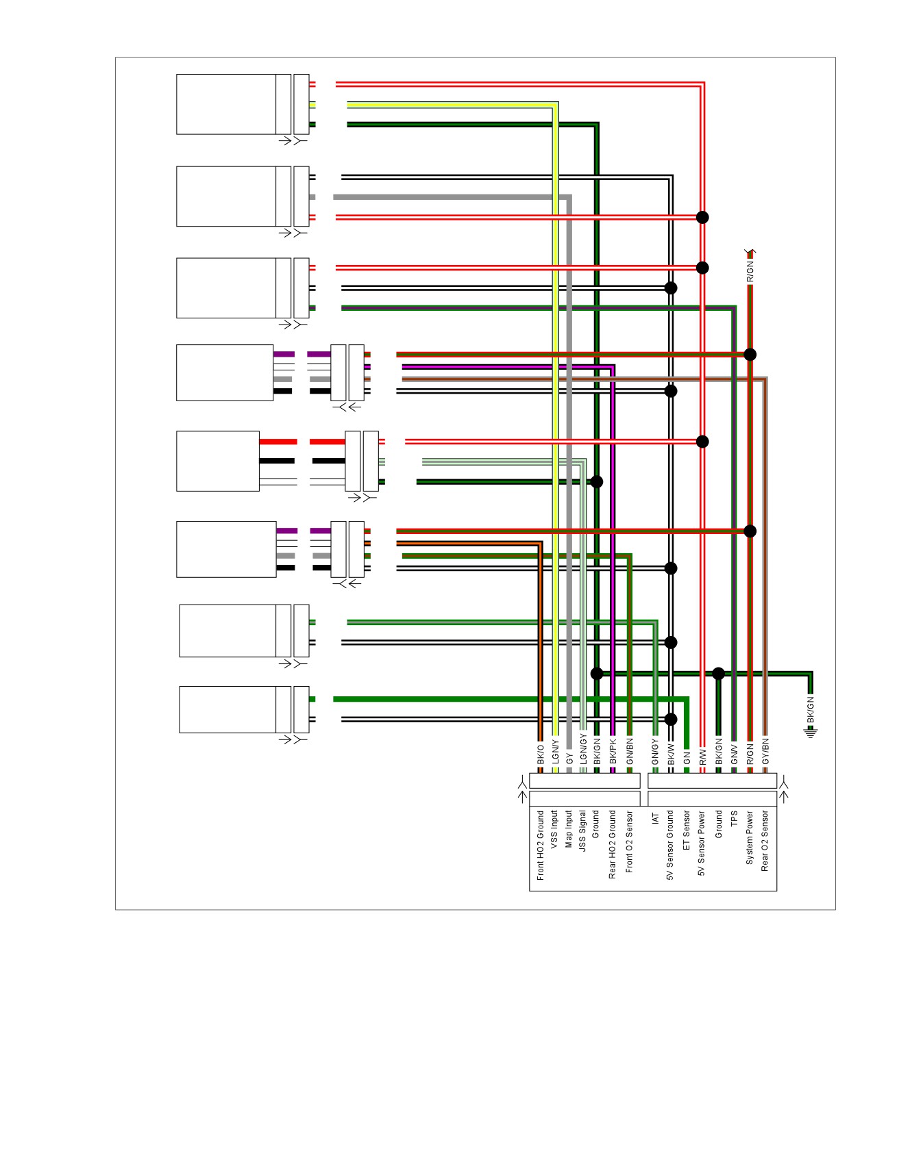
Figure 6-28. Sensor Circuit
2013 Softail Diagnostics: Engine Management 6-53

HOME
3. Is debris present?
DTC P0502
a. Yes. Clean debris from VSS and install.
PART NUMBER
TOOL NAME
b. No. Replace VSS.
HD-41404
HARNESS CONNECTOR TEST KIT
DTC P0503
HD-50390-1
BREAKOUT BOX
HD-50390-4
ECM CABLE
PART NUMBER
TOOL NAME
HD-50390-4-P
ECM OVERLAY
HD-41404
HARNESS CONNECTOR TEST KIT
HD-50390-1
BREAKOUT BOX
Table 6-45. DTC P0502 Diagnostic Faults
HD-50390-4
ECM CABLE
POSSIBLE CAUSES
HD-50390-4-P
ECM OVERLAY
VSS malfunction
Open or short to ground in signal circuit
Table 6-46. DTC P0503 Diagnostic Faults
Open or short to ground in 5V reference circuit
POSSIBLE CAUSES
1. VSS Connections Test
VSS malfunction
1. Turn IGN OFF.
Short to voltage in signal circuit
Open ground
2. Disconnect VSS [65].
5V reference shorted to battery voltage
3. Turn IGN ON.
4. Using HARNESS CONNECTOR TEST KIT (Part No. HD-
1. VSS Sensor Power Shorted to Voltage
41404), test voltage between [65B] terminal A (R/W) wire
Test
and ground.
1. Turn IGN OFF.
5. Is voltage approximately 5.0V?
2. Disconnect VSS [65].
a. Yes. Go to Test 2.
3. Turn IGN ON.
b. No. Repair open on (R/W) wire.
4. Using HARNESS CONNECTOR TEST KIT (Part No. HD-
2. Signal Wire Short to Ground Test
41404), test voltage between [65B] terminals A (R/W) wire
and C (BK/GN) wire.
1. Turn IGN OFF.
5. Is voltage greater than 6.0V?
2. Connect BREAKOUT BOX (Part No. HD-50390-1) and
a. Yes. Repair short to voltage on (R/W) wire.
ECM CABLE (Part No. HD-50390-4) to wiring harness
[78B-1] and [78B-2], leaving ECM [78A-1] and [78A-2]
b. No. Go to Test 2.
disconnected. See 1.2 DIAGNOSTIC TOOLS.
2. Signal Wire Short to Voltage Test
3. Verify ECM OVERLAY (Part No. HD-50390-4-P) is in
position on BOB.
1. Test voltage between [65B] terminal B (LGN/Y) wire and
ground.
4. Test continuity between BOB [78-1] terminals 4 and 10.
2. Is voltage above 6.0V?
5. Is continuity present?
a. Yes. Repair short to voltage on (LGN/Y) wire.
a. Yes. Repair short to ground on (LGN/Y) wire.
b. No. Go to Test 3.
b. No. Go to Test 3.
3. VSS Ground Wire Open Test
3. Signal Wire Open Test
1. Connect BREAKOUT BOX (Part No. HD-50390-1) and
1. Test continuity between BOB [78-1] terminal 4 and [65B]
ECM CABLE (Part No. HD-50390-4) to wiring harness
terminal B (LGN/Y) wire.
[78B-1] and [78B-2], leaving ECM [78A-1] and [78A-2]
2. Is continuity present?
disconnected. See 1.2 DIAGNOSTIC TOOLS.
a. Yes. Go to Test 4.
2. Verify ECM OVERLAY (Part No. HD-50390-4-P) is in
b. No. Repair open on (LGN/Y) wire.
position on BOB.
3. Test continuity between BOB [78-1] terminal 10 and [65B]
4. Dirty or Damaged Test
terminal C (BK/GN) wire.
1. Remove VSS.
4. Is continuity present?
2. Check for debris on sensor tip.
a. Yes. Go to Test 4.
b. No. Repair open on (BK/GN) wire.
6-54 2013 Softail Diagnostics: Engine Management
HOME
4. Signal Wire Shorted to Sensor Power Test
5. VSS Test
1. Test continuity between BOB [78-1] terminal 4 and [78-2]
1. Connect [78A-1] and [78A-2] to breakout box.
terminal 9.
2. Clear DTC.
2. Is continuity present?
3. Did DTC reset?
a. Yes. Repair short between (LGN/Y) and (R/W) wires.
a. Yes. Replace ECM.
b. No. Go to Test 5.
b. No. Replace VSS.
2013 Softail Diagnostics: Engine Management 6-55
HOME
DTC P0506,
P0507
6.15
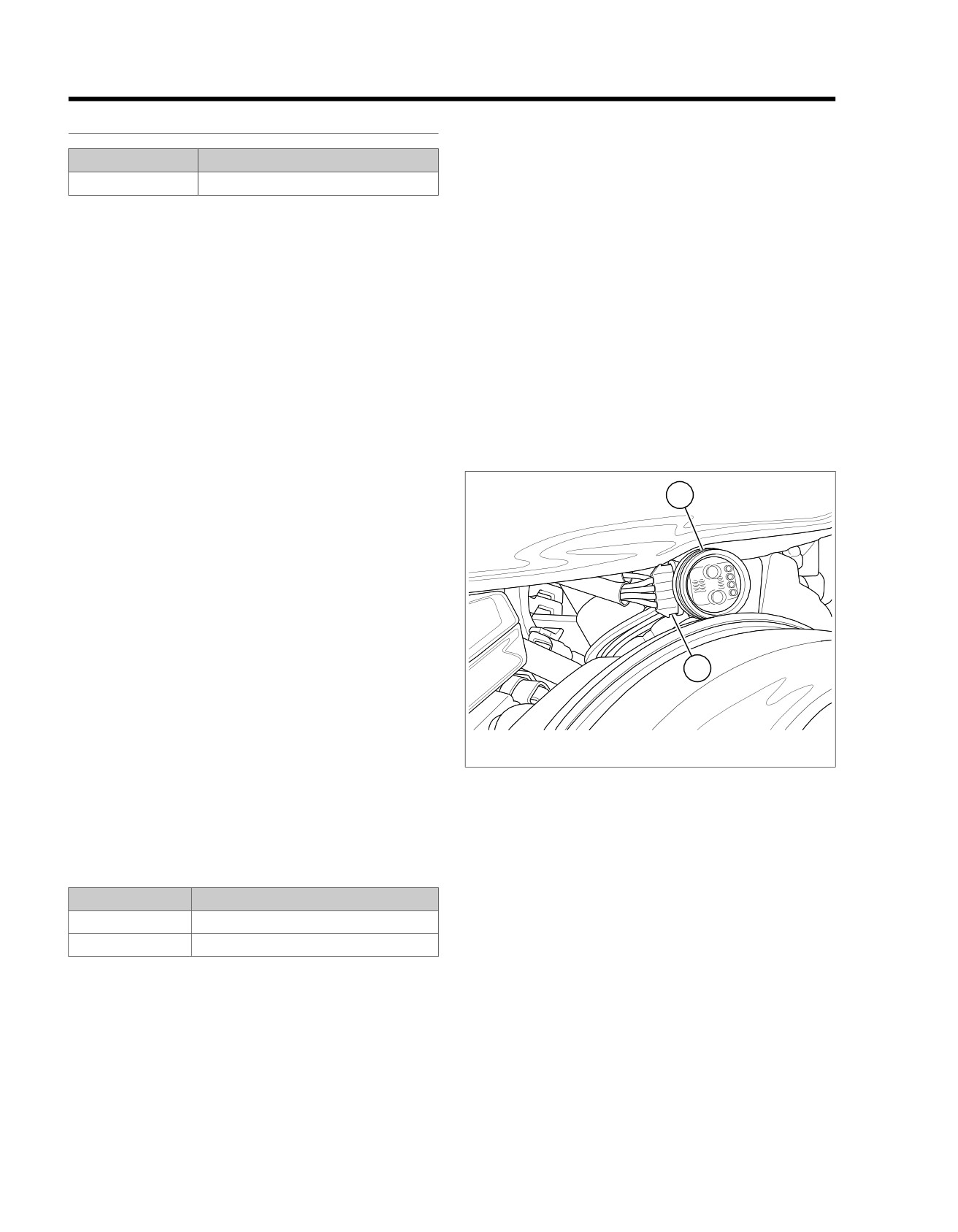
number of conditions such as an intake air leak, improperly
DESCRIPTION AND OPERATION
adjusted throttle stop or a misfiring cylinder.
PART NUMBER
TOOL NAME
•
A non-OE engine configuration can lead to idle instability
and could generate a DTC.
HD-48650
DIGITAL TECHNICIAN II
•
Leaking injectors will cause fuel imbalance and poor idle
The ECM controls engine idle speed by moving the IAC to
quality due to different air/fuel ratios in each cylinder. To
open or close a passage around the throttle plates. It does this
check for leaky injectors, first remove the air box and air
by sending voltage pulses to the proper motor winding of the
filter. Then, with the throttle wide open, turn IGN ON for 2
IAC. This causes the pintle to move in or out of the IAC a given
seconds and then OFF for 2 seconds five consecutive
distance for each pulse received.
times. Replace the fuel injector if there is any evidence of
raw fuel in the bores.
•
To increase idle speed, the ECM retracts the pintle,
allowing more air to flow through the throttle body.
•
Intake leaks.
•
To decrease idle speed, the ECM extends the pintle,
•
Contaminated fuel.
allowing less air to flow through the throttle body. The IAC
•
TPS reading of greater than 1% (possible throttle cable
position can be measured in steps. This can only be done
misadjustment) or battery voltage reading of less than 9V
with DIGITAL TECHNICIAN II (Part No. HD-48650).
or a VSS greater than 0 will disable idle speed control.
•
A high number of steps represents a fully retracted pintle
When disconnecting any connectors always inspect connector
and open passage around throttle plate. This correlates
for corrosion or backed out terminals and repair as required.
with an increase in the amount of air flowing through the
throttle body.
ed03346
1
•
Zero steps represents a fully extended pintle. A zero
reading indicates an abnormal condition in which the pintle
has been fully extended and has consequently closed the
passage around throttle plate. Each time the ignition is
turned OFF, the ECM resets the IAC by sending enough
pulses to extend the pintle and effectively close the throttle
body. The fully extended value is the ECM reference point.
A given number of steps are then calculated by the ECM
for use in setting the proper idle speed and IAC position
for the next start event.
2
NOTE
Idle speed is controlled by the ECM and cannot be adjusted.
Loss of idle speed control will result if the idle rpm is ±200 from
1.
IAC test light
preset idle speed and IAC motor is at zero or maximum for
2.
IAC [87]
greater than 5 seconds. These DTCs may occur with others
for a multiple code situation. Resolve the other codes first to
Figure 6-29. IAC Test Light
correct. A misfire condition or similar symptom affecting idle
can cause P0506 to set. Inspect for these conditions before
diagnosing DTCs.
Table 6-47. Code Description
DTC
DESCRIPTION
P0506
Idle speed control - rpm too low
P0507
Idle speed control - rpm too high
Diagnostic Tips
The following items may impact engine idle speed:
•
A loss of idle speed control does not necessarily imply the
IAC actuator or wiring has failed. It can be caused by a
6-56 2013 Softail Diagnostics: Engine Management
HOME
Connector Information
ed03338
2
3
1
For additional information about the connectors in the following
diagram(s) and diagnostic procedure(s), including the color of
the harness test kit terminal probes, see B.1 CONNECTORS.
7
6
5
4
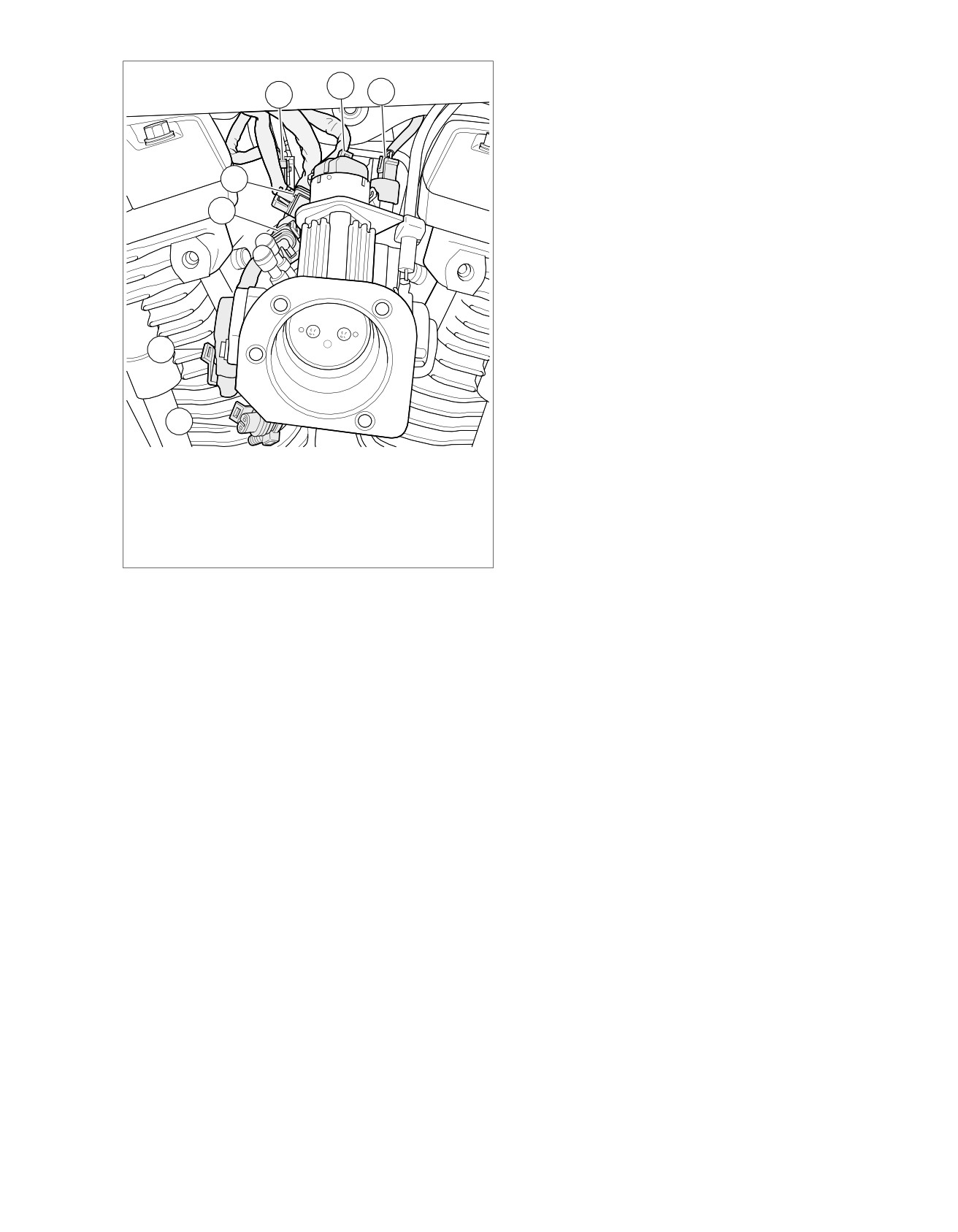
1. Rear fuel injector [85]
2. IAC [87]
3. Front fuel injector [84]
4. Active intake solenoid [178]
5. TPS [88]
6. IAT sensor [89]
7. MAP sensor [80]
Figure 6-30. Between Cylinders Right Side
2013 Softail Diagnostics: Engine Management 6-57
HOME
em00995
[78A-1] [78B-1]
ECM
CKP Sensor Low
18
18
BK
BK
2
2
Sensor Low
CKP
CKP Sensor High
16
16
R
R
1
1
Sensor High
Ground
10
10
BK/GN
[79B] [79A]
Main
R/GN
L3
L3
System Power
BCM
Harness
[242B] [242A]
[179B] [179A]
System Power
16
16
R/GN
CKP Sensor Low
14
14
LGN/BE
LGN/BE
4
4
Feedback
CKP Sensor High
13
13
GY/W
LGN/O
3
3
Actuator
Exhaust
Actuator
IAC A High
12
12
GN/W
BK
2
2
Ground
(HDI)
IAC B Low
11
11
GY/O
R/GN
1
1
System Power
IAC A Low
10
10
BK/GN
GND 2
IAC B High
3
3
LGN/O
Ground
2
2
LGN/V
LGN/V
2
2
Active Intake
AIS
(HDI)
Ground
1
1
GN/O
R/GN
1
1
System Power
[178B] [178A]
[78A-2] [78B-2]
GY/W
A
A
B Low
GN/W
B
B
B High
IAC
GND 1
GY/O
C
C
A Low
GN/O
D
D
A High
[87B] [87A]
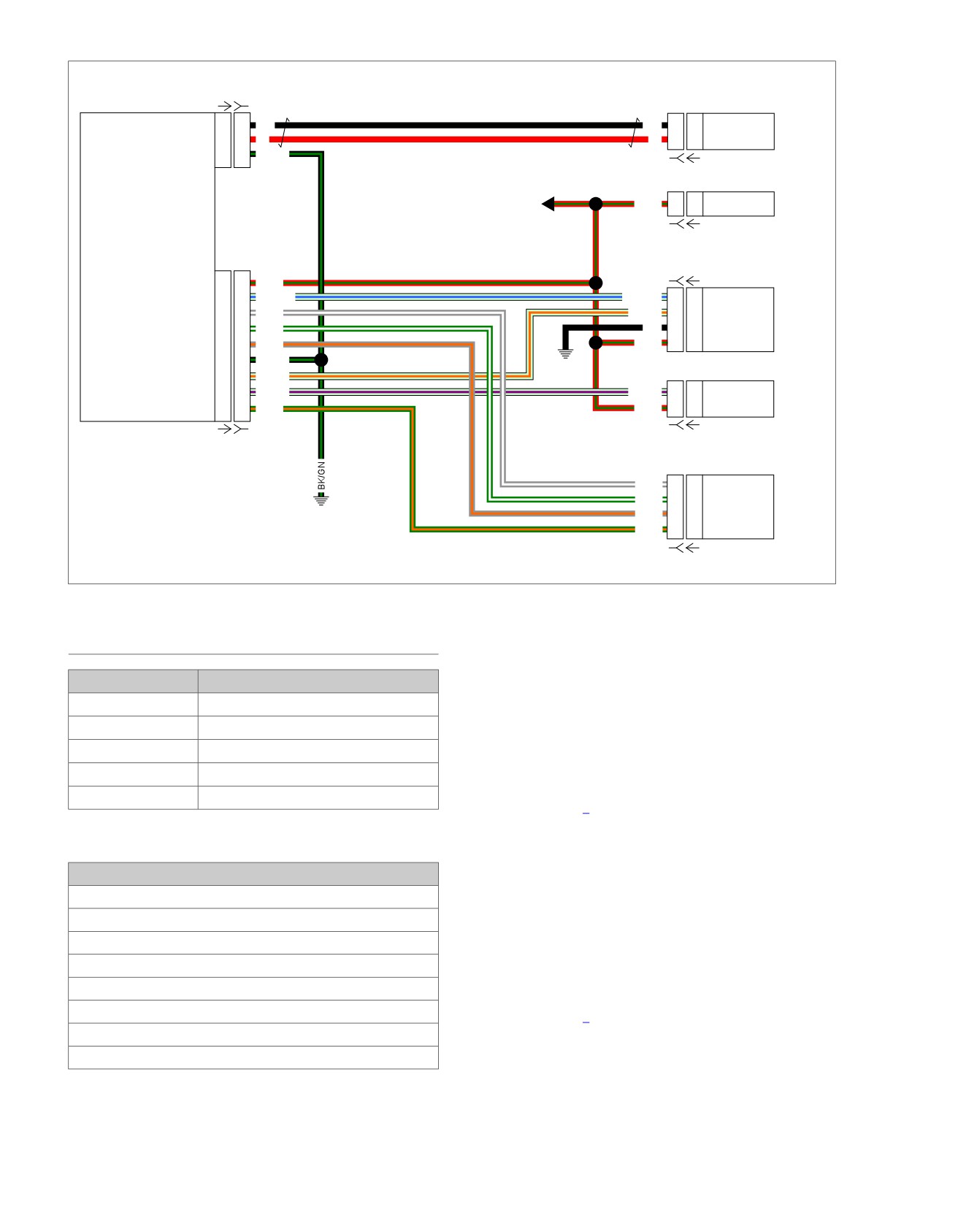
Figure 6-31. Active Exhaust Actuator and AIS Circuit
DTC P0506, P0507
1. IAC Operational Test
1. While watching the IAC pintle for movement turn IGN OFF,
PART NUMBER
TOOL NAME
ON, then OFF.
HD-41199-3
IAC TEST LIGHT
2. Did pintle move?
HD-41404
HARNESS CONNECTOR TEST KIT
a. Yes. IAC system operating properly. Check for
HD-50390-1
BREAKOUT BOX
improperly adjusted throttle stop, vacuum leaks, cyl-
inder misfire, contaminated fuel, leaking injectors and
HD-50390-4
ECM CABLE
engine mechanical failure.
HD-50390-4-P
ECM OVERLAY
b. No. Go to Test 2.
Table 6-48. DTC P0506, P0507 Diagnostic Faults
2. Connector Test
1. Disconnect IAC [87].
POSSIBLE CAUSES
2. Connect IAC TEST LIGHT (Part No. HD-41199-3) to [87B].
IAC malfunction
Short to voltage in circuits
3. Turn IGN ON.
Short to ground in circuits
4. While observing test light, turn IGN OFF.
Open in system power circuit
5. Did both IAC test lights flash alternately?
Short between IAC circuits
a. Yes. Replace IAC.
Open circuits
b. No. Go to Test 3.
Vacuum/air leaks
Fuel system problems
6-58 2013 Softail Diagnostics: Engine Management
HOME
4. Circuits Shorted to Ground Test
Table 6-49. IAC, Wire Color, ECM
1. Test continuity on each IAC wire between BOB and
IAC [87B]
WIRE COLOR
ECM [78-2]
ground. Refer to Table 6-49.
A
GY/W
13
2. Is continuity present on any circuits?
B
GN/W
12
a. Yes. Repair short to ground on appropriate circuit.
C
GY/O
11
b. No. Go to Test 5.
D
GN/O
1
5. Circuits Short to Voltage Test
3. Circuits Open Test
1. Turn IGN ON.
1. Turn IGN OFF.
2. Test voltage between BOB and ground on each IAC wire.
2. Remove test light.
Refer to Table 6-49.
3. Connect BREAKOUT BOX (Part No. HD-50390-1) and
3. Is voltage present on any circuit?
ECM CABLE (Part No. HD-50390-4) to wiring harness
a. Yes. Repair short to voltage in appropriate circuit.
[78B-1] and [78B-2], leaving ECM [78A-1] and [78A-2]
disconnected. See 1.2 DIAGNOSTIC TOOLS.
b. No. Go to Test 6.
4. Verify ECM OVERLAY (Part No. HD-50390-4-P) is in
6. Short Between Circuits Test
position on BOB.
1. Turn IGN OFF.
5. Using HARNESS CONNECTOR TEST KIT (Part No. HD-
41404), test continuity on each IAC wire between BOB
2. Test continuity between each IAC circuit and the other
and [87B]. Refer to Table 6-49.
IAC circuits.
6. Is continuity present on all circuits?
3. Is continuity present between any two IAC circuits?
a. Yes. Go to Test 4.
a. Yes. Repair short between IAC circuits.
b. No. Repair open in appropriate circuit.
b. No. Replace ECM.
2013 Softail Diagnostics: Engine Management 6-59
HOME
DTC P0603,
P0605
6.16
DESCRIPTION AND OPERATION
ed03469
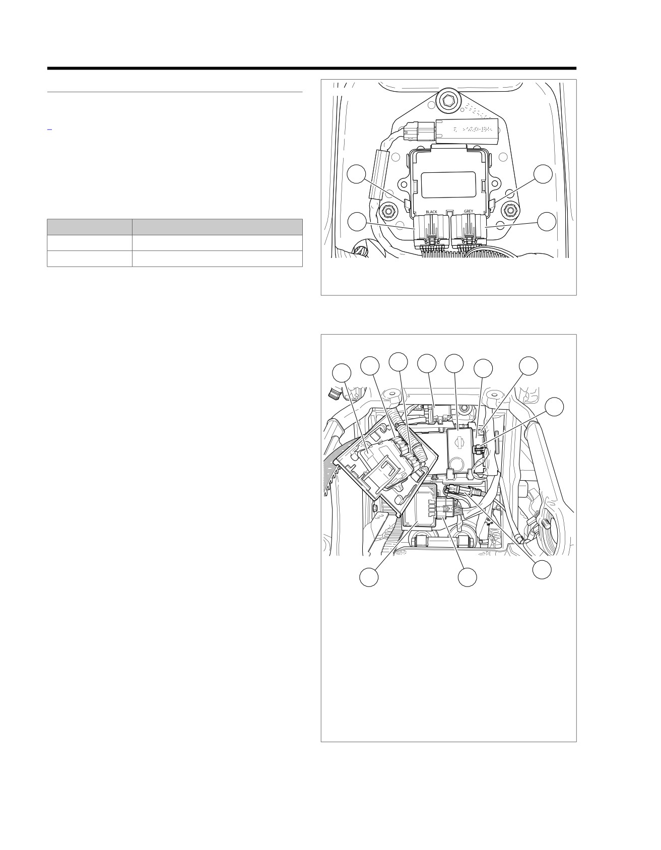
See Figure 6-32 and Figure 6-33. The DTCs listed indicate a
failure which requires replacement of the ECM. Refer to
Table 6-50.
NOTE
After replacing ECM, perform password learning procedure
and clear DTCs using odometer self-diagnostics. See 2.1 INI-
3
3
TIAL DIAGNOSTICS, Odometer Self-Diagnostics.
Table 6-50. Code Description
1
2
DTC
DESCRIPTION
P0603
ECM EEPROM memory error
P0605
ECM flash memory error
1. ECM [78-1]
2. ECM [78-2]
DTC P0603 Test
3. Retaining clips
1. Clear DTCs.
Figure 6-32. ECM [78-1] and [78-2]: Except FXSB
2. Turn IGN ON.
3. Check DTCs.
ed03462
4. Did DTC reset?
3
4
5
a. Yes. Replace ECM.
2
7
6
1
b. No. System operating properly.
DTC P0605 Test
8
1. Clear DTCs.
2. Attempt to program ECM using correct calibration.
3. Start engine.
4. Check DTCs.
5. Did DTC reset?
a. Yes. Replace ECM.
b. No. System operating properly.
9
11
10
1. ECM
2. ECM [78-2]
3. ECM [78-1]
4. Purge solenoid [95] (back side of purge
solenoid)
5. Security siren
6. BCM
7. BCM [242] (back side of BCM)
8. Security siren [142]
9. Rear WSS [168]
10. ABS [166]
11. ABS ECU
Figure 6-33. Electrical Panel: FXSB
6-60 2013 Softail Diagnostics: Engine Management
HOME
DTC P0641
6.17
DESCRIPTION AND OPERATION
Connector Information
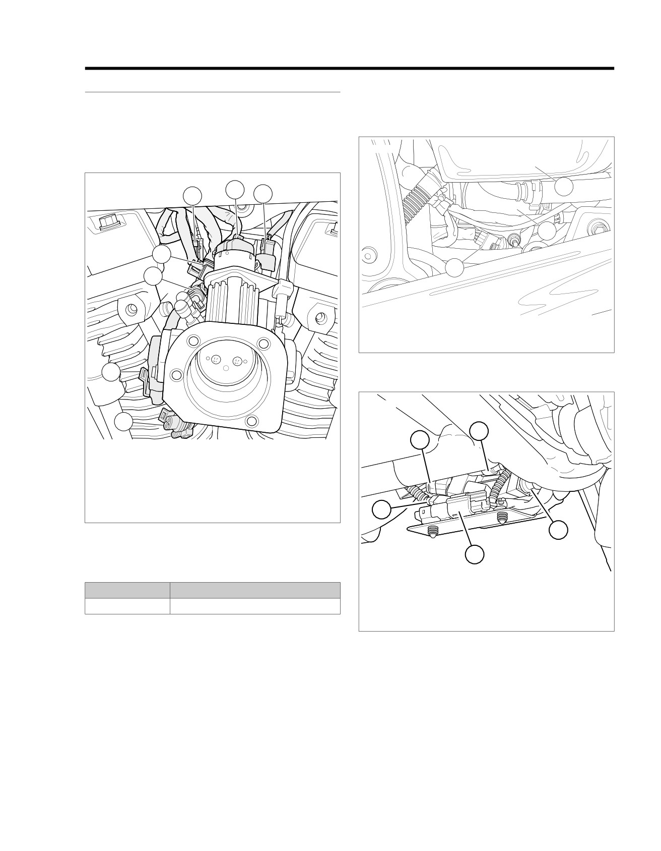
See Figure 6-34, Figure 6-35 and Figure 6-36. The ECM sup-
For additional information about the connectors in the following
plies 5V to the VSS, MAP, TPS and JSS from [78-2] terminal
diagram(s) and diagnostic procedure(s), including the color of
9. These sensors may have individual codes along with this
the harness test kit terminal probes, see B.1 CONNECTORS.
code since they all share the 5V ref circuit. If the ECM sees a
voltage of less than 4V or greater than 6V on the 5V ref circuit,
ed03304
P0641 will be set.
ed03338
2
2
1
3
3
7
1
6
1. VSS
2. Oil tank
3. Starter
Figure 6-35. VSS
5
ed03292
4
2
1
1. Rear fuel injector [85]
2. IAC [87]
3. Front fuel injector [84]
4. Active intake solenoid [178]
5. TPS [88]
6. IAT sensor [89]
5
7. MAP sensor [80]
3
Figure 6-34. Between Cylinders Right Side
4
Table 6-51. Code Description
1.
Voltage regulator to stator [47]
DTC
DESCRIPTION
2.
Front HO2 sensor [138]
3.
Voltage regulator [77]
P0641
5V Vref out of range
4.
JSS [133]
Any of these conditions will set a DTC P0641:
5.
CKP sensor [79]
•
Short to ground on the 5V sensor power circuit.
Figure 6-36. Under Voltage Regulator
•
Short to voltage on the 5V sensor power circuit.
•
VSS fault or malfunction.
•
MAP sensor fault or malfunction.
•
TPS fault or malfunction.
•
JSS (HDI) fault or malfunction.
•
ECM fault or malfunction.
2013 Softail Diagnostics: Engine Management 6-61
HOME
em00996
5V Sensor Power
A
A
R/W
VSS
VSS Input
B
B
LGN/Y
Ground
C
C
BK/GN
[65A] [65B]
5V Sensor Ground
A
A
BK/W
MAP
MAP Input
B
B
GY
Sensor
5V Sensor Power
C
C
R/W
To BCM
[80A] [80B]
5V Sensor Power
1
1
R/W
TPS
5V Sensor Ground
2
2
BK/W
TPS
3
3
GN/V
[88A] [88B]
System Power
V
1
1
R/GN
Rear HO2
Rear O2 Heater Ground
W
2
2
BK/PK
Sensor
Rear O2 Sensor
GY
3
3
GY/BN
5V Sensor Ground
BK
4
4
BK/W
[138B] [138A]
5V Sensor Ground
R
1
1
R/W
JSS
JSS Signal
BK
2
2
LGN/GY
(HDI)
Sensor Ground
W
3
3
BK/GN
[133A] [133B]
System Power
V
1
1
R/GN
Front HO2
Front O2 Heater Ground
W
2
2
BK/O
Sensor
Front O2 Sensor
GY
3
3
GN/BN
5V Sensor Ground
BK
4
4
BK/W
[138B] [138A]
IAT
1
1
GN/GY
IAT
Sensor
5V Sensor Ground
2
2
BK/W
[89A] [89B]
ET Sensor
A
A
GN
ET
Sensor
5V Sensor Ground
B
B
BK/W
[90A] [90B]
GND 1
[78B-1]
3
4
7
8
10
15
17
6
7
8
9
10
15
16
17
[78B-2]
[78A-1]
3
4
7
8
10
15
17
6
7
8
9
10
15
16
17
[78A-2]
ECM
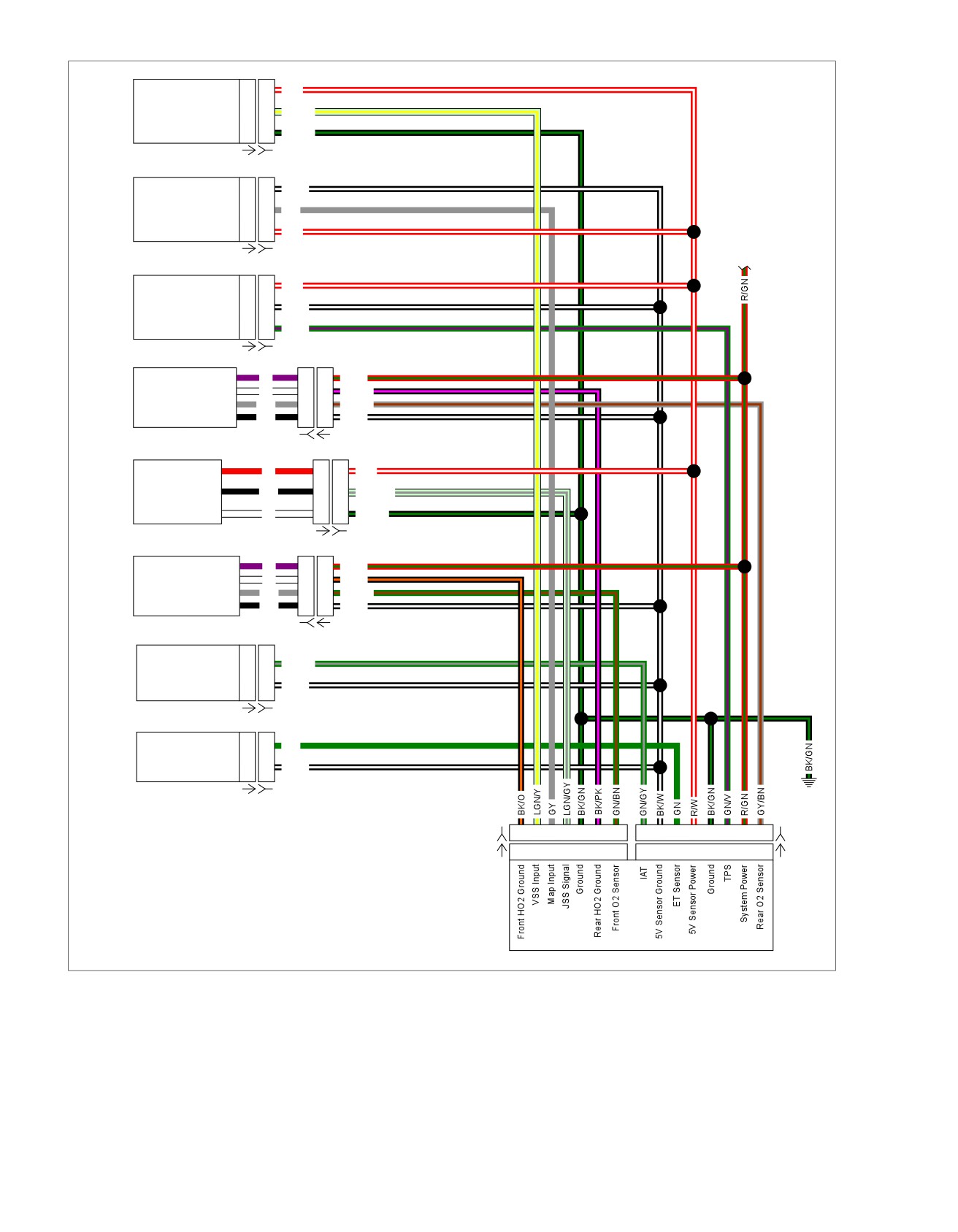
Figure 6-37. Sensor Circuit
6-62 2013 Softail Diagnostics: Engine Management

HOME
DTC P0641
3. MAP Power Circuit Below Range Test
1. Turn IGN OFF.
PART NUMBER
TOOL NAME
2. Disconnect MAP sensor [80].
HD-41404
HARNESS CONNECTOR TEST KIT
3. Turn IGN ON.
HD-50390-1
BREAKOUT BOX
4. Test voltage between BOB [78-2] terminals 9 and 10.
HD-50390-4
ECM CABLE
HD-50390-4-P
ECM OVERLAY
5. Is voltage less than 4V?
a. Yes. Go to Test 4.
Table 6-52. DTC P0641 Diagnostic Faults
b. No. Replace MAP sensor.
POSSIBLE CAUSES
4. VSS Circuit Below Range Test
Short to ground on the 5V sensor power circuit
1. Turn IGN OFF.
Short to voltage on the 5V sensor power circuit
2. Disconnect VSS [65].
VSS fault or malfunction
3. Turn IGN ON.
MAP sensor fault or malfunction
4. Test voltage between BOB [78-2] terminals 9 and 10.
TPS fault or malfunction
5. Is voltage less than 4V?
JSS (HDI) fault or malfunction
a. Yes, with JSS. Go to Test 5.
1. 5V Sensor Short to Voltage Test
b. Yes, without JSS. Go to Test 6.
1. Turn IGN OFF.
c. No. Replace VSS.
2. Connect BREAKOUT BOX (Part No. HD-50390-1) and
ECM CABLE (Part No. HD-50390-4) between wiring har-
5. JSS Circuit Below Range Test
ness [78B-1] and [78B-2] and ECM [78A-1] and [78A-2].
1. Turn IGN OFF.
See 1.2 DIAGNOSTIC TOOLS.
2. Disconnect JSS [133].
3. Verify ECM OVERLAY (Part No. HD-50390-4-P) is in
position on BOB.
3. Turn IGN ON.
4. Turn IGN ON.
4. Test voltage between BOB [78-2] terminals 9 and 10.
5. Using HARNESS CONNECTOR TEST KIT (Part No. HD-
5. Is voltage less than 4V?
41404), test voltage between BOB [78-2] terminal 9 and
a. Yes. Go to Test 6.
ground.
b. No. Replace JSS.
6. Is voltage between 4-6V?
a. Yes. Concern is intermittent. See 1.3 DIAGNOSTICS
6. Circuit Short to Ground Test
AND TROUBLESHOOTING, Wiggle Test.
1. Disconnect ECM from breakout box.
b. No. Greater than 6V. Repair short to voltage on
2. Test continuity between BOB [78-2] terminal 9 and ground.
(R/W) wire.
3. Is continuity present?
c. No. Less than 4V. Go to Test 2.
a. Yes. Repair short to ground in (R/W) wire.
2. TPS Circuit Below Range Test
b. No. Go to Test 7.
1. Turn IGN OFF.
7. Circuit Shorted to Sensor Ground Circuit
2. Disconnect TPS [88].
Test
3. Turn IGN ON.
1. Test continuity between BOB [78-2] terminals 9 and 7.
4. Test voltage between BOB [78-2] terminals 9 and 10.
2. Is continuity present?
5. Is voltage less than 4V?
a. Yes. Repair short between (R/W) and (BK/W) wires.
a. Yes. Go to Test 3.
b. No. Replace ECM.
b. No. Replace TPS.
2013 Softail Diagnostics: Engine Management 6-63
HOME
DTC P0661,
P0662
6.18
DESCRIPTION AND OPERATION
ed03354
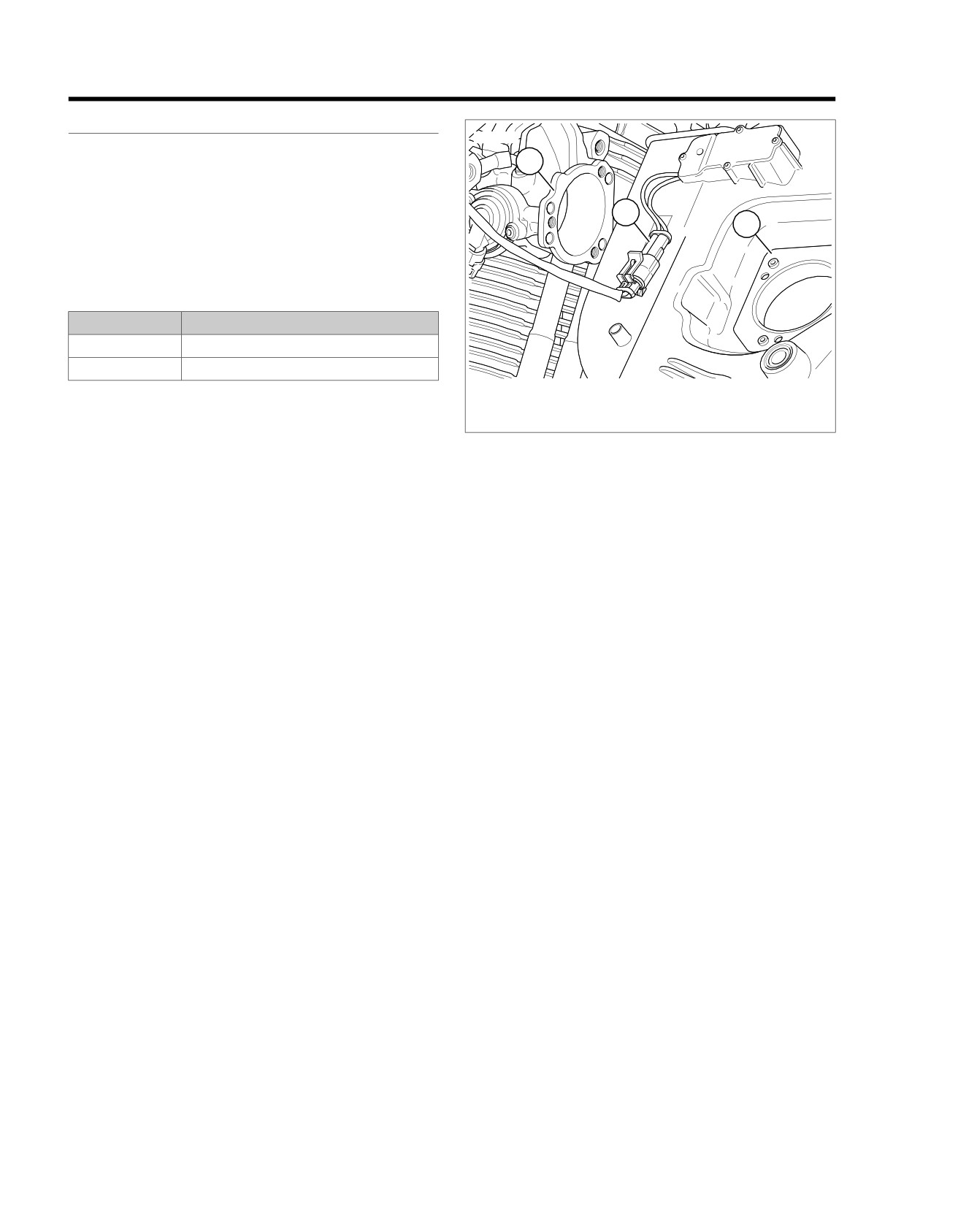
Active intake solenoid (AIS) is included on HDI vehicles only.
1
See Figure 6-39. The AIS regulates the amount of air entering
the air cleaner. The AIS opens when vehicle speed exceeds
45 mph (70 km/h) with 50% or greater throttle opening. Once
2
open, active intake will close when vehicle speed falls below
3
40 mph (65 km/h). The power for the AIS comes from the BCM.
The ECM provides the path to ground to trigger the AIS.
Table 6-53. Code Description
DTC
DESCRIPTION
P0661
AIS low/open
P0662
AIS shorted/high
1. Intake module
2. Intake solenoid connector [178]
3. Air cleaner backing plate
Figure 6-38. Intake Solenoid Connector Location
NOTE
The AIS and active exhaust actuator share the same power
source and function simultaneously.
Connector Information
For additional information about the connectors in the following
diagram(s) and diagnostic procedure(s), including the color of
the harness test kit terminal probes, see B.1 CONNECTORS.
6-64 2013 Softail Diagnostics: Engine Management
HOME
em00995
[78A-1] [78B-1]
ECM
CKP Sensor Low
18
18
BK
BK
2
2
Sensor Low
CKP
CKP Sensor High
16
16
R
R
1
1
Sensor High
Ground
10
10
BK/GN
[79B] [79A]
Main
R/GN
L3
L3
System Power
BCM
Harness
[242B] [242A]
[179B] [179A]
System Power
16
16
R/GN
CKP Sensor Low
14
14
LGN/BE
LGN/BE
4
4
Feedback
CKP Sensor High
13
13
GY/W
LGN/O
3
3
Actuator
Exhaust
Actuator
IAC A High
12
12
GN/W
BK
2
2
Ground
(HDI)
IAC B Low
11
11
GY/O
R/GN
1
1
System Power
IAC A Low
10
10
BK/GN
GND 2
IAC B High
3
3
LGN/O
Ground
2
2
LGN/V
LGN/V
2
2
Active Intake
AIS
(HDI)
Ground
1
1
GN/O
R/GN
1
1
System Power
[178B] [178A]
[78A-2] [78B-2]
GY/W
A
A
B Low
GN/W
B
B
B High
IAC
GND 1
GY/O
C
C
A Low
GN/O
D
D
A High
[87B] [87A]
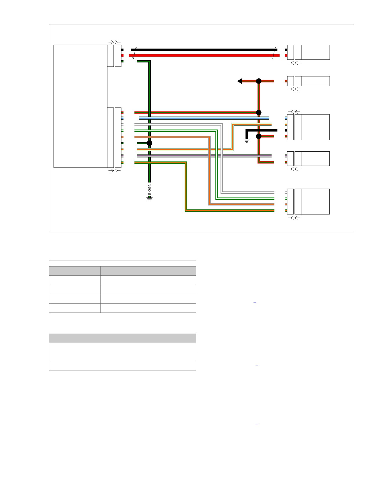
Figure 6-39. Active Exhaust Actuator and AIS Circuit
DTC P0661
4. Using HARNESS CONNECTOR TEST KIT (Part No. HD-
41404), jump BOB [78-2] terminals 2 to 10.
PART NUMBER
TOOL NAME
5. Turn IGN ON.
HD-41404
HARNESS CONNECTOR TEST KIT
6. Does AIS activate immediately?
HD-50390-1
BREAKOUT BOX
a. Yes. Replace ECM.
HD-50390-4
ECM CABLE
b. No. Go to Test 2.
HD-50390-4-P
ECM OVERLAY
2. Resistance Test
1. Turn IGN OFF.
Table 6-54. DTC P0661 Diagnostic Faults
2. Disconnect AIS [178].
POSSIBLE CAUSES
3. Test resistance between [178A] terminals 1 and 2.
AIS malfunction
4. Is resistance between 16-20 Ohms?
Active intake shorted low
a. Yes. Go to Test 3.
Open in circuit
b. No. Replace AIS.
1. AIS Test
1. Turn IGN OFF.
3. Open Ground Wire Test
1. Test continuity between BOB [78-2] terminal 2 to AIS
2. Connect BREAKOUT BOX (Part No. HD-50390-1) and
[178B] terminal 2 (LGN/V) wire.
ECM CABLE (Part No. HD-50390-4) to wiring harness
[78B-1] and [78B-2], leaving ECM [78A-1] and [78A-2]
2. Is continuity present?
disconnected. See 1.2 DIAGNOSTIC TOOLS.
a. Yes. Go to Test 4.
3. Verify ECM OVERLAY (Part No. HD-50390-4-P) is in
b. No. Repair open in (LGN/V) wire.
position on BOB.
2013 Softail Diagnostics: Engine Management 6-65
HOME
2. Disconnect AIS [178].
4. Low Short to Ground Test
1. Test continuity between BOB [78-2] terminal 2 and ground.
3. Using HARNESS CONNECTOR TEST KIT (Part No. HD-
41404), test resistance between [178A] terminals 1 and
2. Is continuity present?
2.
a. Yes. Repair short to ground on (LGN/V) wire.
4. Is resistance between 16-20 Ohms?
b. No. Go to Test 5.
a. Yes. Go to Test 2.
5. Open Supply Wire Test
b. No. Replace AIS.
1. Test continuity between [78B-2] terminal 2 and [178B]
2. Short to Voltage Test
terminal 1 (R/GN) wire.
1. Turn IGN ON.
2. Is continuity present?
2. Test voltage between [178B] terminal 2 and ground.
a. Yes. Replace ECM.
3. Is voltage greater than 5.0V?
b. No. Repair open in (R/GN) wire.
a. Yes. Repair short to voltage on (LGN/V) wire
DTC P0662
b. No. Replace ECM.
PART NUMBER
TOOL NAME
HD-41404
HARNESS CONNECTOR TEST KIT
Table 6-55. DTC P0662 Diagnostic Faults
POSSIBLE CAUSES
Active intake shorted high
1. AIS Resistance Test
1. Turn IGN OFF.
6-66 2013 Softail Diagnostics: Engine Management
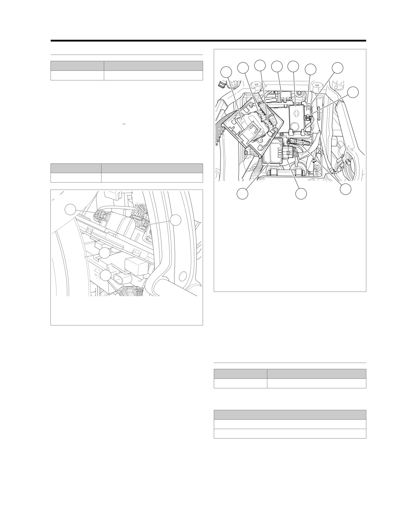
HOME
DTC P1009
6.19
GENERAL
ed03462
PART NUMBER
TOOL NAME
3
2
4
5
7
6
1
HD-48650
DIGITAL TECHNICIAN II
Password Problem
8
The ECM and BCM exchange passwords during operation. An
incorrect password will set a DTC. If any U-codes exist,
troubleshoot the higher priority codes prior to performing the
tests in this section. Refer to Table 2-1.
NOTE
Vehicle will not start if BCM is disconnected.
Table 6-56. Code Description
DTC
DESCRIPTION
P1009
Incorrect password
9
11
10
ed03310
1
1.
ECM
2
2.
ECM [78-2]
3.
ECM [78-1]
4.
Purge solenoid [95] (back side of purge
solenoid)
5.
Security siren
4
6.
BCM
7.
BCM [242] (back side of BCM)
8.
Security siren [142]
9.
Rear WSS [168]
3
10. ABS [166]
11. ABS ECU
Figure 6-41. Electrical Panel: FXSB
1.
BCM battery power [259]
2.
BCM [242]
3.
Rear WSS [168]
Diagnostic Tips
4.
Rear tire
This code will usually appear after replacing the ECM or BCM.
Figure 6-40. BCM [242]: Except FXSB
New modules must be programmed using DIGITAL TECHNI-
CIAN II (Part No. HD-48650). After parts are programmed and
matched correctly for specific vehicle, clear codes.
DTC P1009
PART NUMBER
TOOL NAME
HD-48650
DIGITAL TECHNICIAN II
Table 6-57. DTC P1009 Diagnostic Faults
POSSIBLE CAUSES
ECM malfunction
BCM malfunction
2013 Softail Diagnostics: Engine Management 6-67