Harley Davidson Softail Delux FLSTN BIKE 2011-2015. Electrical Diagnostics - page 13
HOME
2. Is continuity present?
2. Test continuity between BOB [78-2] terminals 8 and 7.
a. Yes. Repair short between (GN) and (R/W) wires.
3. Is continuity present?
b. No. Go to Test 5.
a. Yes. Replace ECM.
b. No. Replace ET sensor.
5. ET Sensor Test
1. Connect [90].
6-28 2013 Softail Diagnostics: Engine Management
HOME
DTC P0122,
P0123
6.9
DESCRIPTION AND OPERATION
NOTE
The ECM supplies a 5V signal on [78-2] terminal 9 to terminal
The MAP, JSS (HDI), VSS and TPSs are connected to the
1 of the TPS. The TPS sends a signal back to the ECM on [78-
same reference line (+5V REF). If the line goes to ground or
2] terminal 15. The returned signal varies in voltage according
open, multiple trouble codes will be set (DTCs P0107, P0108
to throttle position.
and P0122, P0123, P1501 or P1502). Start with the DTC having
the lowest ranking value.
•
At idle (closed throttle), the signal is typically in the range
of 0.2-0.8V.
Check for the following conditions:
•
At wide open throttle, the signal is normally 4.0-4.9V.
•
Poor connection: Inspect ECM harness connector [78B-
1] and [78B-2] for backed out terminals, improper mating,
DTC P0122 or P0123 will set if the TPS voltage signal does
inoperative locks, improperly formed or damaged ter-
not fall within the acceptable range.
minals, poor terminal-to-wire connection and damaged
harness.
Table 6-20. Code Description
•
Perform 1.3 DIAGNOSTICS AND TROUBLESHOOTING,
DTC
DESCRIPTION
Wiggle Test to locate intermittents: If connections and
harness check out OK, monitor TPS voltage using a mul-
P0122
TPS low/open
timeter while moving related connectors and wiring har-
P0123
TPS high
ness. A TPS voltage change when a part is moved indic-
ates an intermittent.
Diagnostic Tips
•
TPS scaling: Observe the TPS voltage display while
The multimeter reads throttle position in Volts. Voltage should
opening the throttle with engine stopped and ignition switch
increase at a steady rate as the throttle is moved from idle to
ON. Display should vary from closed throttle TPS voltage
wide open. A short to ground or open on the (GN/V) or (R/W)
(when throttle is closed) to greater than 4.0V (when throttle
wires also will result in a DTC P0122. A short to ground or open
is held wide open). As the throttle is slowly moved, the
on the (R/W) wire (+5V REF) sets multiple codes.
voltage should change gradually without spikes or low
voltages being observed.
ed03338
2
1
3
Connector Information
For additional information about the connectors in the following
diagram(s) and diagnostic procedure(s), including the color of
the harness test kit terminal probes, see B.1 CONNECTORS.
7
6
5
4
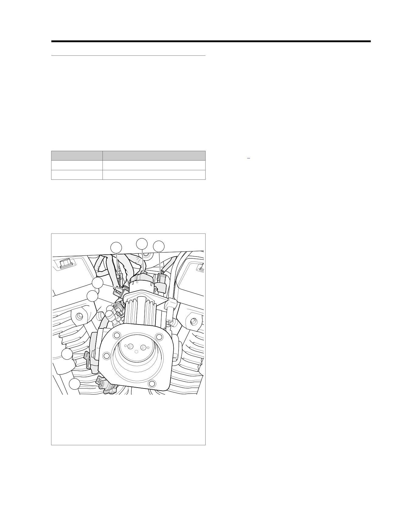
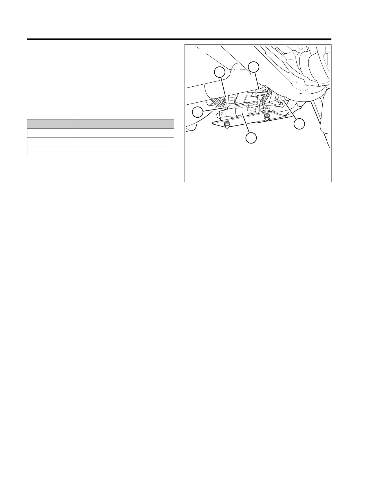
1. Rear fuel injector [85]
2. IAC [87]
3. Front fuel injector [84]
4. Active intake solenoid [178]
5. TPS [88]
6. IAT sensor [89]
7. MAP sensor [80]
Figure 6-17. Between Cylinders Right Side
2013 Softail Diagnostics: Engine Management 6-29
HOME
em00996
5V Sensor Power
A
A
R/W
VSS
VSS Input
B
B
LGN/Y
Ground
C
C
BK/GN
[65A] [65B]
5V Sensor Ground
A
A
BK/W
MAP
MAP Input
B
B
GY
Sensor
5V Sensor Power
C
C
R/W
To BCM
[80A] [80B]
5V Sensor Power
1
1
R/W
TPS
5V Sensor Ground
2
2
BK/W
TPS
3
3
GN/V
[88A] [88B]
System Power
V
1
1
R/GN
Rear HO2
Rear O2 Heater Ground
W
2
2
BK/PK
Sensor
Rear O2 Sensor
GY
3
3
GY/BN
5V Sensor Ground
BK
4
4
BK/W
[138B] [138A]
5V Sensor Ground
R
1
1
R/W
JSS
JSS Signal
BK
2
2
LGN/GY
(HDI)
Sensor Ground
W
3
3
BK/GN
[133A] [133B]
System Power
V
1
1
R/GN
Front HO2
Front O2 Heater Ground
W
2
2
BK/O
Sensor
Front O2 Sensor
GY
3
3
GN/BN
5V Sensor Ground
BK
4
4
BK/W
[138B] [138A]
IAT
1
1
GN/GY
IAT
Sensor
5V Sensor Ground
2
2
BK/W
[89A] [89B]
ET Sensor
A
A
GN
ET
Sensor
5V Sensor Ground
B
B
BK/W
[90A] [90B]
GND 1
[78B-1]
3
4
7
8
10
15
17
6
7
8
9
10
15
16
17
[78B-2]
[78A-1]
3
4
7
8
10
15
17
6
7
8
9
10
15
16
17
[78A-2]
ECM
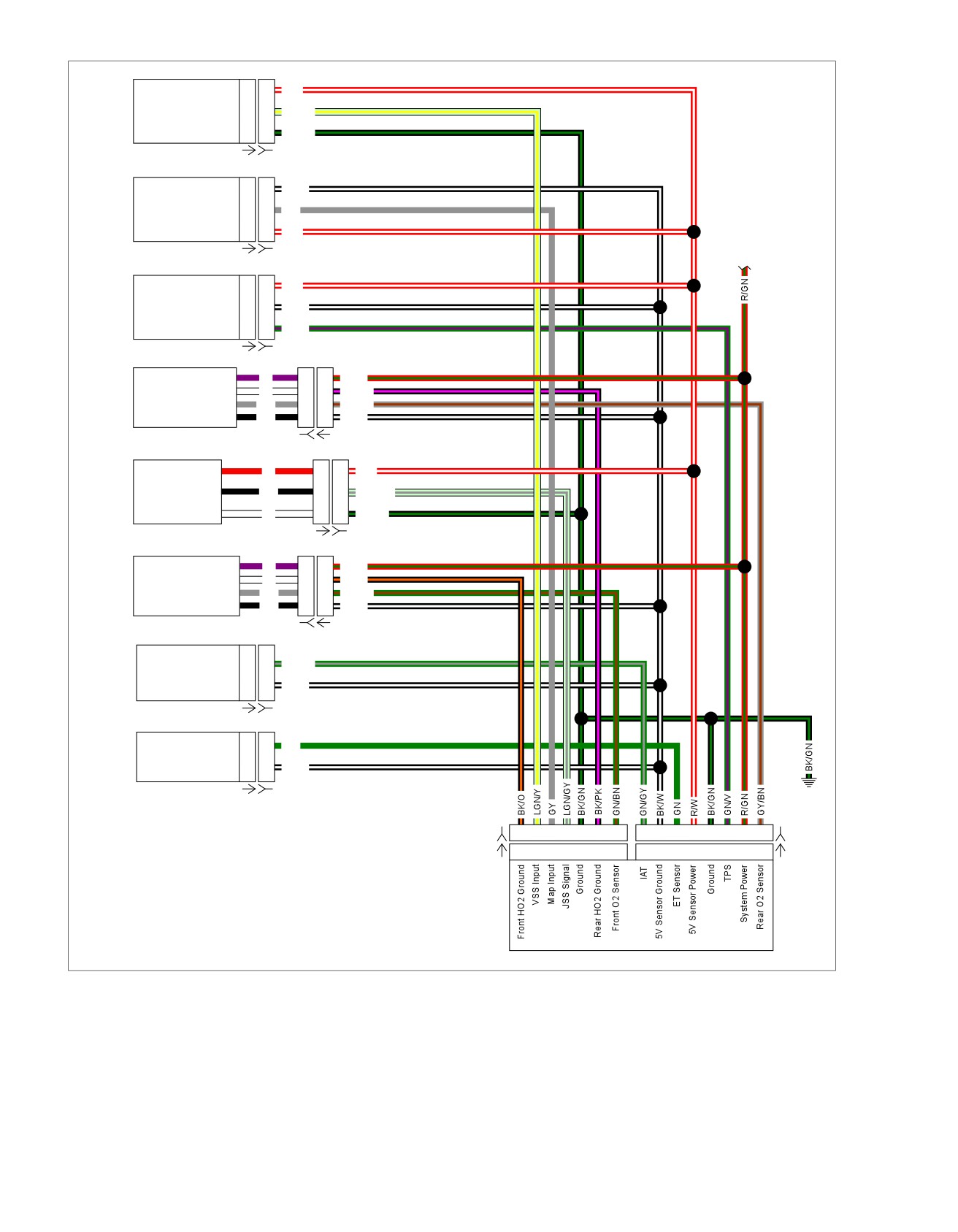
Figure 6-18. Sensor Circuit
6-30 2013 Softail Diagnostics: Engine Management
HOME
5. Is continuity present?
DTC P0122
a. Yes. Go to Test 4.
PART NUMBER
TOOL NAME
b. No. Repair open in (GN/V) wire.
HD-41404
HARNESS CONNECTOR TEST KIT
4. Signal Wire Shorted to Ground Test
HD-50390-1
BREAKOUT BOX
1. Test continuity between BOB [78-2] terminal
15 and
HD-50390-4
ECM CABLE
ground.
HD-50390-4-P
ECM OVERLAY
2. Is continuity present?
a. Yes. Repair short to ground in (GN/V) wire.
Table 6-21. DTC P0122 Diagnostic Faults
b. No. Go to Test 5.
POSSIBLE CAUSES
5. Signal Wire Shorted to Sensor Ground
TPS malfunction
Test
Open or short to ground in 5V reference circuit
1. Test continuity between BOB [78-2] terminals 15 and 7.
Short to ground in signal circuit
Open in TPS sensor wire
2. Is continuity present?
a. Yes. Repair short between (GN/V) and (BK/W) wires.
1. TPS Circuit Test
b. No. Replace ECM.
1. Turn IGN OFF.
2. Disconnect TPS [88].
6. 5V Sensor Power Open Wire Test
3. Using HARNESS CONNECTOR TEST KIT (Part No. HD-
1. Turn IGN OFF.
41404), connect a test wire across [88B] terminals 1(R/W)
2. Connect BREAKOUT BOX (Part No. HD-50390-1) and
wire and 3 (GN/V) wire.
ECM CABLE (Part No. HD-50390-4) to wiring harness
4. Clear DTCs.
[78B-1] and [78B-2], leaving ECM [78A-1] and [78A-2]
disconnected. See 1.2 DIAGNOSTIC TOOLS.
5. Turn IGN OFF and ON.
3. Verify ECM OVERLAY (Part No. HD-50390-4-P) is in
6. Check DTCs.
position on BOB.
7. Did DTC reset?
4. Test continuity between [88B] terminal 1 (R/W) wire and
a. Yes. Go to Test 2.
BOB [78-2] terminal 9.
b. No. Replace TPS.
5. Is continuity present?
a. Yes. Replace ECM.
2. Signal Voltage Test
b. No. Repair open in (R/W) wire.
1. Turn IGN OFF.
DTC P0123
2. Remove test wire.
3. Turn IGN ON.
PART NUMBER
TOOL NAME
4. Test voltage between [88B] terminal 1 (R/W) wire and
HD-41404
HARNESS CONNECTOR TEST KIT
ground.
HD-50390-1
BREAKOUT BOX
5. Is voltage approximately 5V?
HD-50390-4
ECM CABLE
a. Yes. Go to Test 3.
HD-50390-4-P
ECM OVERLAY
b. No. Go to Test 6.
3. Signal Wire Continuity Test
Table 6-22. DTC P0123 Diagnostic Faults
1. Turn IGN OFF.
POSSIBLE CAUSES
2. Connect BREAKOUT BOX (Part No. HD-50390-1) and
TPS malfunction
ECM CABLE (Part No. HD-50390-4) to wiring harness
Short to voltage in 5V reference circuit
[78B-1] and [78B-2], leaving ECM [78A-1] and [78A-2]
Open sensor ground
disconnected. See 1.2 DIAGNOSTIC TOOLS.
3. Verify ECM OVERLAY (Part No. HD-50390-4-P) is in
1. TPS Test
position on BOB.
1. Turn IGN OFF.
4. Test continuity between [88B] terminal 3 (GN/V) wire and
2. Disconnect TPS [88].
BOB [78-2] terminal 15.
2013 Softail Diagnostics: Engine Management 6-31
HOME
3. Clear DTCs.
3. Is voltage present?
a. Yes. Repair short to voltage in (GN/V) wire.
4. Turn IGN OFF and ON.
b. No. Replace ECM.
5. Check DTCs.
6. Did DTC reset?
4. 5V Shorted to Battery Voltage Test
a. Yes. Go to Test 2.
1. Using the HARNESS CONNECTOR TEST KIT (Part
b. No. Go to Test 4.
No. HD-41404), test voltage between [88B] terminal 1
(R/W) wire and ground.
2. Signal Wire Short to 5V Test
2. Is voltage greater than 5.25V?
1. Turn IGN OFF.
a. Yes. Repair short to voltage in (R/W) wire.
2. Disconnect ECM [78-1] and [78-2].
b. No. Go to Test 5.
3. Using HARNESS CONNECTOR TEST KIT (Part No. HD-
5. Ground Wire Open Test
41404), test continuity between [88B] terminals 1 (R/W)
wire and 3 (GN/V) wire.
1. Turn IGN OFF.
4. Is continuity present?
2. Connect BREAKOUT BOX (Part No. HD-50390-1) and
a. Yes. Repair short between (R/W) and (GN/V) wires.
ECM CABLE (Part No. HD-50390-4) to wiring harness
[78B-1] and [78B-2], leaving ECM [78A-1] and [78A-2]
b. No. Go to Test 3.
disconnected. See 1.2 DIAGNOSTIC TOOLS.
3. Signal Wire Short to Voltage Test
3. Verify ECM OVERLAY (Part No. HD-50390-4-P) is in
position on BOB.
1. Turn IGN ON.
4. Test continuity between [88B] terminal 2 (BK/W) wire and
2. Test voltage between [88B] terminal 3 (GN/V) wire and
BOB [78-2] terminal 7.
ground.
5. Is continuity present?
a. Yes. Replace TPS.
b. No. Repair open in (BK/W) wire.
6-32 2013 Softail Diagnostics: Engine Management
HOME
DTC P0031, P0032, P0051, P0052, P0131, P0132,
P0134, P0151, P0152, P0154
6.10
DESCRIPTION AND OPERATION
Diagnostic Tips
The HO2S DTCs will not illuminate the check engine lamp for
PART NUMBER
TOOL NAME
current or historic codes and will only be indicated by DIGITAL
HD-48650
DIGITAL TECHNICIAN II
TECHNICIAN II (Part No. HD-48650) or odometer self-dia-
gnostics. All historic HO2S DTCs are to be ignored and cleared.
The multimeter displays the signal from the HO2S in Volts.
The HO2S provides a signal to the ECM which indicates
This voltage will have an average value tending towards lean,
whether the engine is running rich or lean.
rich or ideal value depending on operating temperature of the
•
A P0131 (front) or P0151 (rear) is set when the ECM
engine, engine speed and throttle position. An open/short to
detects an excessively lean condition for a specified length
voltage or short to ground in the (PK/O) wire (front) and
of time. DTCs may also set if HO2S fails.
(PK/GN) wire (rear) will cause the engine to run rich (short to
ground) or lean (short to voltage) until fault is detected. Once
•
A P0132 (front) or P0152 (rear) is set when the ECM
fault is detected, vehicle will run in open loop.
detects an excessively rich condition for a specified length
of time. This can be caused by oil contamination or fuel
Check for the following conditions:
injector malfunctions. DTCs may also set if HO2S fails.
•
Poor connection: Inspect the ECM [78-1] and [78-2], fuel
•
A P0134 is set when the front O2 sensor circuit is open
injector
[84, 85] and HO2S [137, 138] connectors for
or sensor is too cold to respond. A P0154 is set when the
backed out terminals, improper mating, inoperative locks,
rear O2 sensor circuit is open or sensor is too cold to
improperly formed or damaged terminals, poor terminal-
respond. Excessive oil usage may also cause these codes
to-wire connection and damaged harnesses.
to set.
•
Dirty/stuck open injectors: The vehicle may run lean
•
When the air/fuel mixture is ideal, approximately 14.6 parts
(dirty/clogged injectors) or rich (stuck open injectors) if
air to 1 part fuel, the voltage will be approximately 0.45V
there are injector problems. This could also cause poor
when measuring across the sensor. If the voltage is
fuel economy and performance.
measured from the sensor (terminals 46 or 66) to ground,
•
Leaking injectors: This causes fuel imbalance and poor
the voltage will read approximately 1.2V. This difference
idle quality due to different air/fuel ratios in each cylinder.
is due to an internal bias in the ECM. When using DIGITAL
To check for leaky injectors, first remove the air box and
TECHNICIAN II (Part No. HD-48650), the O2 voltage
air filter. Then, with the throttle wide open, turn IGN ON
reading is displayed in the higher range 0.7-1.7V.
for 2 seconds and then OFF for 2 seconds five consecutive
times. Replace the fuel injector if there is any evidence of
Table 6-23. Code Description
raw fuel in the bores. See Fuel Injectors in the service
manual.
DTC
DESCRIPTION
P0031
Front O2 heater open/low
•
Loose HO2S: If an HO2S is loose, engine performance
may be affected. This could also show up as a slow
P0032
Front O2 heater shorted/high
changing HO2S voltage.
P0051
Rear O2 heater open/low
•
Loose/leaking exhaust: This can cause a poor ground
P0052
Rear O2 heater shorted/high
connection for the sensor or allow fresh air into the exhaust
P0131
Front O2 sensor low or engine running lean
system. If fresh air enters exhaust system, the HO2S will
read a lean condition, causing the system to go rich.
P0132
Engine front O2 running rich
•
Engine misfire: See 6.29 MISFIRE AT IDLE OR UNDER
P0134
Front O2 sensor open/not responding/high
LOAD.
P0151
Rear O2 sensor low or engine running lean
•
Intake leaks: See the service manual.
P0152
Engine rear O2 running rich
Connector Information
P0154
Rear O2 sensor open/not responding/high
For additional information about the connectors in the following
The heater portion of the HO2S is powered through the system
diagram(s) and diagnostic procedure(s), including the color of
relay. The front and rear HO2S heaters share a common
the harness test kit terminal probes, see B.1 CONNECTORS.
ground through terminal 31 of the ECM. If the ECM recognizes
an open or short in the heater circuit, it will set either DTC
P0031 or P0032.
2013 Softail Diagnostics: Engine Management 6-33
HOME
em00996
5V Sensor Power
A
A
R/W
VSS
VSS Input
B
B
LGN/Y
Ground
C
C
BK/GN
[65A] [65B]
5V Sensor Ground
A
A
BK/W
MAP
MAP Input
B
B
GY
Sensor
5V Sensor Power
C
C
R/W
To BCM
[80A] [80B]
5V Sensor Power
1
1
R/W
TPS
5V Sensor Ground
2
2
BK/W
TPS
3
3
GN/V
[88A] [88B]
System Power
V
1
1
R/GN
Rear HO2
Rear O2 Heater Ground
W
2
2
BK/PK
Sensor
Rear O2 Sensor
GY
3
3
GY/BN
5V Sensor Ground
BK
4
4
BK/W
[138B] [138A]
5V Sensor Ground
R
1
1
R/W
JSS
JSS Signal
BK
2
2
LGN/GY
(HDI)
Sensor Ground
W
3
3
BK/GN
[133A] [133B]
System Power
V
1
1
R/GN
Front HO2
Front O2 Heater Ground
W
2
2
BK/O
Sensor
Front O2 Sensor
GY
3
3
GN/BN
5V Sensor Ground
BK
4
4
BK/W
[138B] [138A]
IAT
1
1
GN/GY
IAT
Sensor
5V Sensor Ground
2
2
BK/W
[89A] [89B]
ET Sensor
A
A
GN
ET
Sensor
5V Sensor Ground
B
B
BK/W
[90A] [90B]
GND 1
[78B-1]
3
4
7
8
10
15
17
6
7
8
9
10
15
16
17
[78B-2]
[78A-1]
3
4
7
8
10
15
17
6
7
8
9
10
15
16
17
[78A-2]
ECM
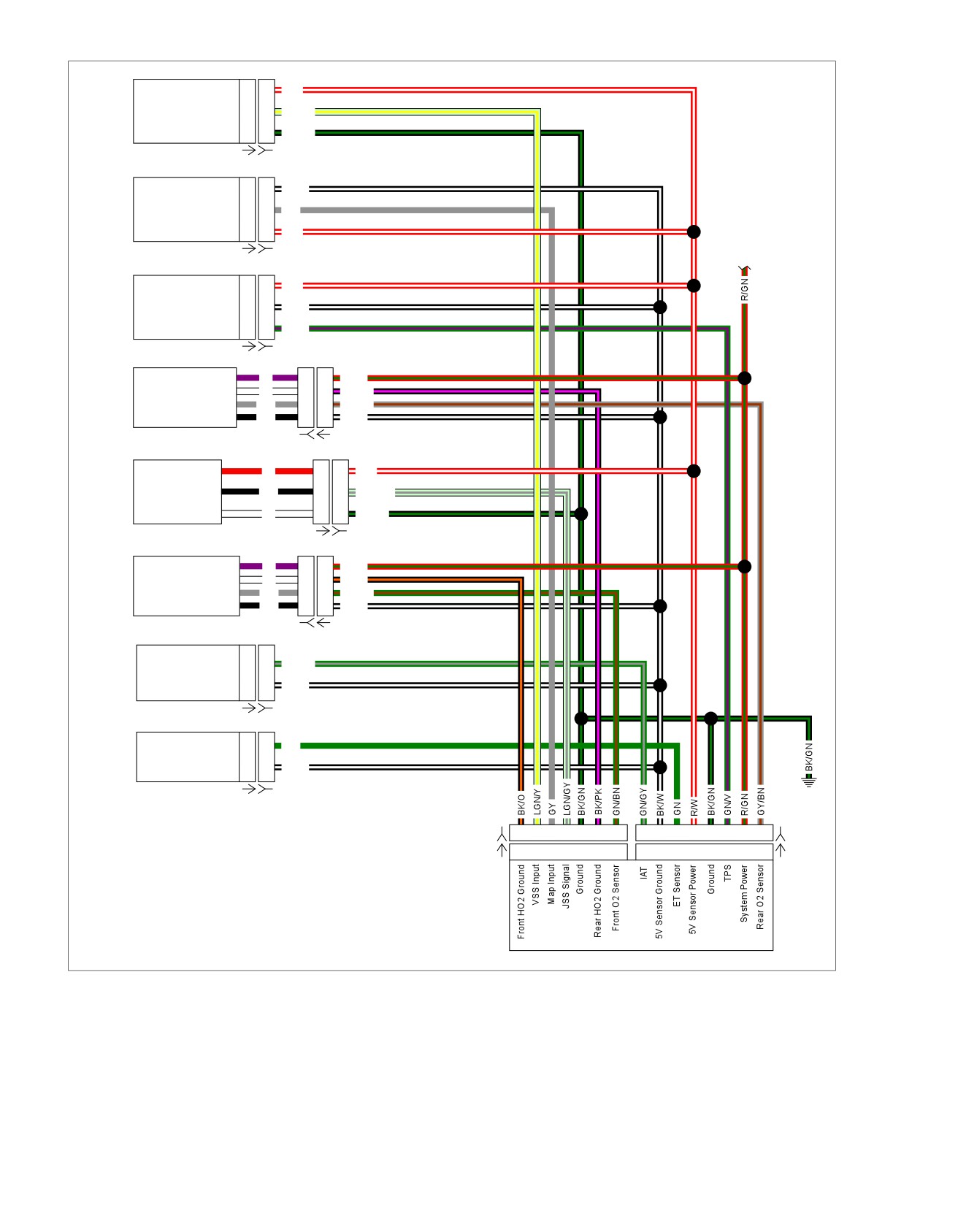
Figure 6-19. Sensor Circuit
6-34 2013 Softail Diagnostics: Engine Management
HOME
2. Is resistance between 13.5-23.5 Ohms?
DTC P0031
a. Yes. Replace ECM.
PART NUMBER
TOOL NAME
b. No. Replace front HO2S.
HD-41404
HARNESS CONNECTOR TEST KIT
DTC P0032
HD-50390-1
BREAKOUT BOX
HD-50390-4
ECM CABLE
PART NUMBER
TOOL NAME
HD-50390-4-P
ECM OVERLAY
HD-50390-1
BREAKOUT BOX
HD-50390-4
ECM CABLE
Table 6-24. DTC P0031 Diagnostic Faults
HD-50390-4-P
ECM OVERLAY
POSSIBLE CAUSES
Open or short to ground on front HO2 circuit
Table 6-25. DTC P0032 Diagnostic Faults
HO2 malfunction
POSSIBLE CAUSES
Open in sensor power circuit
Front HO2 circuit shorted to 12V
1. Front HO2S Voltage Test
HO2 malfunction
1. Turn IGN OFF.
1. Front HO2S Shorted to Voltage Test
2. Disconnect front HO2S [138].
1. Turn IGN OFF.
3. Turn IGN ON.
2. Connect BREAKOUT BOX (Part No. HD-50390-1) and
4. Using HARNESS CONNECTOR TEST KIT (Part No. HD-
ECM CABLE (Part No. HD-50390-4) to wiring harness
41404), test voltage between [138A] terminal 1 (R/GN)
[78B-1] and [78B-2], leaving ECM [78A-1] and [78A-2]
wire and ground.
disconnected. See 1.2 DIAGNOSTIC TOOLS.
5. Is battery voltage present?
3. Verify ECM OVERLAY (Part No. HD-50390-4-P) is in
position on BOB.
a. Yes. Go to Test 2.
4. Test voltage between BOB [78-1] terminal 3 and ground.
b. No. Repair open in (R/GN) wire.
5. Is voltage present?
2. Open Ground Test
a. Yes. Repair short to voltage on (BK/O) wire.
1. Turn IGN OFF.
b. No. Go to Test 2.
2. Connect BREAKOUT BOX (Part No. HD-50390-1) and
ECM CABLE (Part No. HD-50390-4) to wiring harness
2. Resistance Test
[78B-1] and [78B-2], leaving ECM [78A-1] and [78A-2]
1. Turn IGN OFF.
disconnected. See 1.2 DIAGNOSTIC TOOLS.
2. Disconnect front HO2S [138].
3. Verify ECM OVERLAY (Part No. HD-50390-4-P) is in
position on BOB.
3. Test resistance between [138B] terminals 1 (R/GN) wire
and 2 (BK/O) wire.
4. Test continuity between BOB [78-1] terminal 3 and [138A]
terminal 2 (BK/O) wire.
4. Is resistance between 13.5-23.5 Ohms?
a. Yes. Replace ECM.
5. Is continuity present?
a. Yes. Go to Test 3.
b. No. Replace front HO2S.
b. No. Repair open in (BK/O) wire.
3. Short to Ground Test
1. Test for continuity between BOB [78-1] terminal 3 and
ground.
2. Is continuity present?
a. Yes. Repair short to ground in (BK/O) wire.
b. No. Go to Test 4.
4. Resistance Test
1. Test resistance between [138B] terminals 1 (R/GN) wire
and 2 (BK/O) wire.
2013 Softail Diagnostics: Engine Management 6-35
HOME
2. Is resistance between 13.5-23.5 Ohms?
DTC P0051
a. Yes. Replace ECM.
PART NUMBER
TOOL NAME
b. No. Replace rear HO2S.
HD-41404
HARNESS CONNECTOR TEST KIT
DTC P0052
HD-50390-1
BREAKOUT BOX
HD-50390-4
ECM CABLE
PART NUMBER
TOOL NAME
HD-50390-4-P
ECM OVERLAY
HD-41404
HARNESS CONNECTOR TEST KIT
HD-50390-1
BREAKOUT BOX
Table 6-26. DTC P0051 Diagnostic Faults
HD-50390-4
ECM CABLE
POSSIBLE CAUSES
HD-50390-4-P
ECM OVERLAY
Open or short to ground on rear HO2 circuit
HO2 malfunction
Table 6-27. DTC P0052 Diagnostic Faults
Open in sensor power circuit
POSSIBLE CAUSES
1. Rear HO2S Voltage Test
Rear HO2 circuit shorted to voltage
1. Turn IGN OFF.
Rear HO2 malfunction
2. Disconnect rear HO2S [137].
1. Rear HO2S Shorted to Voltage Test
3. Turn IGN ON.
1. Turn IGN OFF.
4. Using HARNESS CONNECTOR TEST KIT (Part No. HD-
2. Connect BREAKOUT BOX (Part No. HD-50390-1) and
41404), test voltage between [137A] terminal 1 (R/GN)
ECM CABLE (Part No. HD-50390-4) to wiring harness
wire and ground.
[78B-1] and [78B-2], leaving ECM [78A-1] and [78A-2]
disconnected. See 1.2 DIAGNOSTIC TOOLS.
5. Is battery voltage present?
a. Yes. Go to Test 2.
3. Verify ECM OVERLAY (Part No. HD-50390-4-P) is in
position on BOB.
b. No. Repair open in (R/GN) wire.
4. Turn IGN ON.
2. Open Ground Test
5. Using HARNESS CONNECTOR TEST KIT (Part No. HD-
1. Turn IGN OFF.
41404), test voltage between BOB [78-1] terminal 15 and
ground.
2. Connect BREAKOUT BOX (Part No. HD-50390-1) and
ECM CABLE (Part No. HD-50390-4) to wiring harness
6. Is voltage present?
[78B-1] and [78B-2], leaving ECM [78A-1] and [78A-2]
a. Yes. Repair short to voltage on (BK/PK) wire.
disconnected. See 1.2 DIAGNOSTIC TOOLS.
b. No.
3. Verify ECM OVERLAY (Part No. HD-50390-4-P) is in
position on BOB.
2. Resistance Test
4. Test continuity between BOB [78-1] terminal 15 and [137A]
1. Turn IGN OFF.
terminal 2 (BK/PK) wire.
2. Test resistance between [137B] terminals 1 (R/GN) wire
5. Is continuity present?
and 2 (BK/PK) wire.
a. Yes. Go to Test 3.
3. Is resistance between 13.5-23.5 Ohms?
b. No. Repair open in (BK/PK) wire.
a. Yes. Replace ECM.
b. No. Replace front HO2S.
3. Short to Ground Test
1. Test continuity between BOB [78-1] terminal
15 and
ground.
2. Is continuity present?
a. Yes. Repair short to ground in (BK/PK) wire.
b. No. Go to Test 4.
4. Resistance Test
1. Test resistance between [137B] terminals 1 (R/GN) wire
and 2 (BK/PK) wire.
6-36 2013 Softail Diagnostics: Engine Management

HOME
2. Is continuity present?
DTC P0131
a. Yes. Repair short between (GN/BN) wire and ground.
PART NUMBER
TOOL NAME
b. No. Replace ECM.
HD-41404
HARNESS CONNECTOR TEST KIT
5. Operation Test
HD-50390-1
BREAKOUT BOX
1. Connect BREAKOUT BOX (Part No. HD-50390-1) and
HD-50390-4
ECM CABLE
ECM CABLE (Part No. HD-50390-4) between wiring har-
HD-50390-4-P
ECM OVERLAY
ness [78B-1] and [78B-2] and ECM [78A-1] and [78A-2].
See 1.2 DIAGNOSTIC TOOLS.
Table 6-28. DTC P0131 Diagnostic Faults
2. Verify ECM OVERLAY (Part No. HD-50390-4-P) is in
position on BOB.
POSSIBLE CAUSES
3. Connect [138].
Front HO2S malfunction
4. Start engine and allow it to reach operating temperature.
Short to ground in signal circuit
Fuel system malfunction
5. With engine speed at a steady rpm, test voltage between
BOB [78-1] terminal 17 and [78-2] terminal 7.
NOTE
6. Is voltage approximately 0.45V?
Vehicle and sensor must be at ambient room temperature
a. Yes. Replace ECM.
before starting diagnostic test.
b. No. (0.0-0.4V). Perform fuel pressure test. Look for
1. Front HO2S Voltage Test
incorrect ECM calibration, low fuel pressure, air leaks
and dirty injectors. If no issues are found, replace
1. Turn IGN OFF.
HO2S.
2. Disconnect front HO2S [138].
DTC P0132
3. Turn IGN ON.
4. Using HARNESS CONNECTOR TEST KIT (Part No. HD-
PART NUMBER
TOOL NAME
41404), test voltage between [138A] terminal 3 (GN/BN)
HD-41404
HARNESS CONNECTOR TEST KIT
wire, to ground.
HD-50390-1
BREAKOUT BOX
5. Is voltage approximately 5V?
HD-50390-4
ECM CABLE
a. Yes. Go to Test 5.
HD-50390-4-P
ECM OVERLAY
b. No. Go to Test 2.
2. HO2S Test
Table 6-29. DTC P0132 Diagnostic Faults
1. Test continuity between [138B] terminal 3 (GY) wire and
POSSIBLE CAUSES
ground.
Front HO2S malfunction
2. Is continuity present?
Fuel system malfunction
a. Yes. Replace HO2S.
1. Front HO2S Operation Test
b. No. Go to Test 3.
1. Turn IGN OFF.
3. Signal Wire Shorted to Sensor Ground
2. Connect BREAKOUT BOX (Part No. HD-50390-1) and
Test
ECM CABLE (Part No. HD-50390-4) between wiring har-
1. Turn IGN OFF.
ness [78B-1] and [78B-2] and ECM [78A-1] and [78A-2].
See 1.2 DIAGNOSTIC TOOLS.
2. Disconnect ECM [78-1] and [78-2].
3. Verify ECM OVERLAY (Part No. HD-50390-4-P) is in
3. Test continuity between [138A] terminals 3 (GN/BN) wire
position on BOB.
and 4 (BK/W) wire.
4. Start engine and allow it to reach operating temperature.
4. Is continuity present?
5. With engine speed at a steady rpm, using HARNESS
a. Yes. Repair short between (GN/BN) and (BK/W)
CONNECTOR TEST KIT (Part No. HD-41404), test voltage
wires.
between BOB [78-1] terminal 17 and [78-2] terminal 7.
b. No. Go to Test 4.
4. Signal Wire Shorted to Ground Test
1. Test continuity between [138A] terminal 3 (GN/BN) wire
and ground.
2013 Softail Diagnostics: Engine Management 6-37
HOME
6. Is voltage approximately 0.45V?
3. Signal Wire Open Test
a. Yes. Replace ECM.
1. Test continuity between [138A] terminal 3 (GN/BN) wire
b. No. (0.6-1.0V) Perform fuel pressure test. Look for
and BOB [78-1] terminal 17.
incorrect ECM calibration, high fuel pressure, stuck
2. Is continuity present?
open or leaking injectors. If no issues are found,
a. Yes. Replace ECM.
replace the HO2S.
b. No. Repair open in (GN/BN) wire.
DTC P0134
DTC P0151
PART NUMBER
TOOL NAME
HD-41404
HARNESS CONNECTOR TEST KIT
PART NUMBER
TOOL NAME
HD-50390-1
BREAKOUT BOX
HD-41404
HARNESS CONNECTOR TEST KIT
HD-50390-4
ECM CABLE
HD-50390-1
BREAKOUT BOX
HD-50390-4-P
ECM OVERLAY
HD-50390-4
ECM CABLE
HD-50390-4-P
ECM OVERLAY
Table 6-30. DTC P0134 Diagnostic Faults
Table 6-31. DTC P0151 Diagnostic Faults
POSSIBLE CAUSES
Front O2 sensor malfunction
POSSIBLE CAUSES
Open or short to voltage in signal circuit
Rear O2 sensor malfunction
Open sensor ground
Short to ground in signal circuit
Fuel system malfunction
1. Front HO2S Signal Wire Short Circuit
Voltage Test
NOTE
1. Turn IGN OFF.
Vehicle and sensor must be at ambient room temperature
before starting diagnostic test.
2. Disconnect front HO2S [138].
1. Rear HO2S Test
3. Turn IGN ON.
1. Turn IGN OFF.
4. Using HARNESS CONNECTOR TEST KIT (Part No. HD-
41404), test voltage between [138A] terminal 3 (GN/BN)
2. Disconnect rear HO2S [137].
wire to ground.
3. Turn IGN ON.
5. Is voltage greater than 5V?
4. Using HARNESS CONNECTOR TEST KIT (Part No. HD-
a. Yes. Repair short to voltage on (GN/BN) wire.
41404), test voltage between [137A] terminal 3 (GY/BN)
b. No. Greater than 4V. Go to Test 2.
wire to ground.
c. No. Less than 4V. Go to Test 3.
5. Is voltage approximately 5V?
a. Yes. Go to Test 5.
2. Open Sensor Ground Test
b. No. Go to Test 2.
1. Turn IGN OFF.
2. HO2S Test
2. Connect BREAKOUT BOX (Part No. HD-50390-1) and
ECM CABLE (Part No. HD-50390-4) to wiring harness
1. Test continuity between [138B] terminal 3 (GY) wire and
[78B-1] and [78B-2], leaving ECM [78A-1] and [78A-2]
ground.
disconnected. See 1.2 DIAGNOSTIC TOOLS.
2. Is continuity present?
3. Verify ECM OVERLAY (Part No. HD-50390-4-P) is in
a. Yes. Replace HO2S.
position on BOB.
b. No. Go to Test 3.
4. Test continuity between [138A] terminal 4 (BK/W) wire
and BOB [78-2] terminal 7.
3. Signal Wire Shorted to Sensor Ground
5. Is continuity present?
Test
a. Yes. Replace front O2 sensor.
1. Turn IGN OFF.
b. No. Repair open on (BK/W) wire.
2. Disconnect ECM [78-1] and [78-2].
3. Test continuity between [137A] terminals 3 (GY/BN) wire
and 4 (BK/W) wire.
6-38 2013 Softail Diagnostics: Engine Management
HOME
4. Is continuity present?
5. Using HARNESS CONNECTOR TEST KIT (Part No. HD-
41404), with engine speed at a steady rpm, test voltage
a. Yes. Repair short between (GY/BN) and (BK/W)
between BOB [78-2] terminal 17 and [78-2] terminal 7.
wires.
6. Is voltage approximately 0.45V?
b. No. Go to Test 4.
a. Yes. Replace ECM.
4. Signal Wire Shorted to Ground Test
b. No. (0.6-1.0V). Perform fuel pressure test. Look for
1. Test continuity between [137A] terminal 3 (GY/BN) wire
incorrect ECM calibration, high fuel pressure, stuck
and ground.
open or leaking injectors. If no issues are found,
replace the HO2S.
2. Is continuity present?
a. Yes. Repair short between (GY/BN) wire and ground.
DTC P0154
b. No. Replace ECM.
PART NUMBER
TOOL NAME
5. Operation Test
HD-41404
HARNESS CONNECTOR TEST KIT
1. Connect BREAKOUT BOX (Part No. HD-50390-1) and
HD-50390-1
BREAKOUT BOX
ECM CABLE (Part No. HD-50390-4) between wiring har-
HD-50390-4
ECM CABLE
ness [78B-1] and [78B-2] and ECM [78A-1] and [78A-2].
See 1.2 DIAGNOSTIC TOOLS.
HD-50390-4-P
ECM OVERLAY
2. Verify ECM OVERLAY (Part No. HD-50390-4-P) is in
position on BOB.
Table 6-33. DTC P0154 Diagnostic Faults
3. Start engine and allow it to reach operating temperature.
POSSIBLE CAUSES
4. With engine speed at a steady rpm, test voltage between
Rear O2 sensor malfunction
BOB [78-2] terminal 17 and [78-2] terminal 7.
Open or short voltage in signal circuit
5. Is voltage approximately 0.45V?
Open sensor ground
a. Yes. Replace ECM.
1. Rear HO2S Signal Wire Short Circuit
b. No. (0.0-0.4V). Perform fuel pressure test. Look for
incorrect ECM calibration, low fuel pressure, air leaks
Voltage Test
and dirty injectors. If no issues are found, replace
1. Turn IGN OFF.
HO2S.
2. Disconnect rear HO2S [137].
DTC P0152
3. Turn IGN ON.
PART NUMBER
TOOL NAME
4. Using HARNESS CONNECTOR TEST KIT (Part No. HD-
41404), test voltage between [137A] terminal 3 (GY/BN)
HD-41404
HARNESS CONNECTOR TEST KIT
wire to ground.
HD-50390-1
BREAKOUT BOX
5. Is voltage greater than 5V?
HD-50390-4
ECM CABLE
a. Yes. Repair short to voltage on (GY/BN) wire.
HD-50390-4-P
ECM OVERLAY
b. No. Greater than 4V. Go to Test 2.
c. No. Less than 4V. Go to Test 3.
Table 6-32. DTC P0152 Diagnostic Faults
2. Open Sensor Ground Test
POSSIBLE CAUSES
1. Turn IGN OFF.
Rear O2 sensor malfunction
Fuel system malfunction
2. Connect BREAKOUT BOX (Part No. HD-50390-1) and
ECM CABLE (Part No. HD-50390-4) to wiring harness
1. Rear HO2S Operation Test
[78B-1] and [78B-2], leaving ECM [78A-1] and [78A-2]
disconnected. See 1.2 DIAGNOSTIC TOOLS.
1. Turn IGN OFF.
3. Verify ECM OVERLAY (Part No. HD-50390-4-P) is in
2. Connect BREAKOUT BOX (Part No. HD-50390-1) and
position on BOB.
ECM CABLE (Part No. HD-50390-4) between wiring har-
ness [78B-1] and [78B-2] and ECM [78A-1] and [78A-2].
4. Test continuity between [137A] terminal 4 (BK/W) wire
See 1.2 DIAGNOSTIC TOOLS.
and BOB [78-2] terminal 7.
3. Verify ECM OVERLAY (Part No. HD-50390-4-P) is in
5. Is continuity present?
position on BOB.
a. Yes. Replace rear HO2S.
4. Start engine and allow it to reach operating temperature.
b. No. Repair open on (BK/W) wire.
2013 Softail Diagnostics: Engine Management 6-39
HOME
2. Is continuity present?
3. Signal Wire Open Test
a. Yes. Replace ECM.
1. Test continuity between [137A] terminal 3 (GY/BN) wire
and BOB [78-2] terminal 17.
b. No. Repair open in (GY/BN) wire.
6-40 2013 Softail Diagnostics: Engine Management
HOME
DTC P0261,
P0262, P0264, P0265
6.11
DESCRIPTION AND OPERATION
ed03338
2
The fuel injectors are solenoids that allow pressurized fuel into
1
3
the intake tract. The injectors are timed to the engine cycle and
triggered sequentially. The power for the injectors comes from
the BCM. The ECM provides the path to ground to trigger the
injectors.
7
NOTE
System power failures or wiring harness problems will cause
6
12V power to be lost to both injectors and the ignition coils.
Table 6-34. Code Description
DTC
DESCRIPTION
P0261
Fuel injector low/open (front)
P0262
Fuel injector high/shorted (front)
5
P0264
Fuel injector low/open (rear)
P0265
Fuel injector high/shorted (rear)
Diagnostic Tips
4
When disconnecting any connectors always inspect connector
for corrosion or backed out terminals and repair as required.
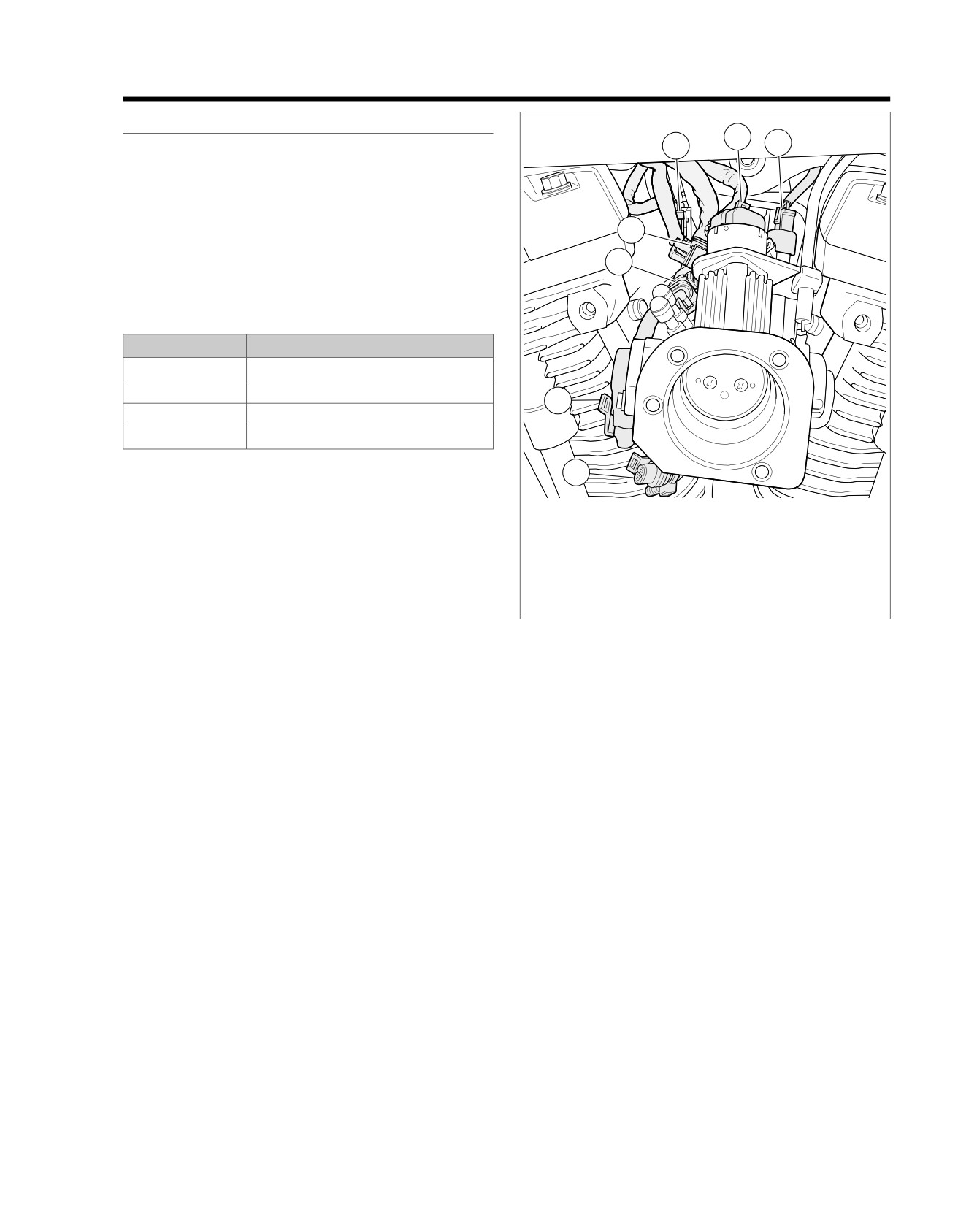
1. Rear fuel injector [85]
2. IAC [87]
Connector Information
3. Front fuel injector [84]
For additional information about the connectors in the following
4. Active intake solenoid [178]
diagram(s) and diagnostic procedure(s), including the color of
5. TPS [88]
the harness test kit terminal probes, see B.1 CONNECTORS.
6. IAT sensor [89]
7. MAP sensor [80]
Figure 6-20. Between Cylinders Right Side
2013 Softail Diagnostics: Engine Management 6-41
HOME
em00997
[242A] [242B]
BCM
System Power
L3
L3
R/GN
Purge
System Power
A
A
R/GN
Solenoid
Purge Solenoid
B
B
LGN/BK
[95A] [95B]
System Power
1
1
R/GN
Active
Ground
2
2
BK
Exhaust
Exhaust Actuator
3
3
LGN/O
Exhaust Feedback
4
4
LGN/BE
[78B-2] [78A-2]
ECM
[179A] [179B]
GY/BN
17
17
Rear HO2 Sensor
Active
Active Intake
BK
2
2
LGN/V
R/GN
16
16
System Power
Intake
LGN/BE
14
14
Exhaust Feedback
System Power
BK
1
1
R/GN
BK/GN
10
10
Ground
BK/W
7
7
5V Sensor Ground
[178A] [178B]
LGN/BK
5
5
Purge Solenoid
LGN/R
4
4
ACR Enable
System Power
V
1
1
R/GN
LGN/O
3
3
Exhaust Actuator
Rear HO2
Rear O2 Heater Ground
W
2
2
BK/PK
LGN/V
2
2
Active Intake
Sensor
Rear O2 Sensor
GY
3
3
GY/BN
5V Sensor Ground
BK
4
4
BK/W
LGN/BN
17
17
Front HO2 Sensor
[138B] [138A]
BK/PK
15
15
Rear HO2 Heater Sensor
BK/GN
10
10
Ground
LGN/BN
9
9
ION Sense
System Power
V
1
1
R/GN
GY/Y
6
6
Rear Fuel Injector
Front HO2
Front O2 Heater Ground
W
2
2
BK/O
GN/Y
5
5
Front Fuel Injector
Sensor
Front O2 Sensor
GY
3
3
GN/BN
BK/O
3
3
Front HO2 Heater Ground
5V Sensor Ground
BK
4
4
BK/W
GN/BE
2
2
Front Ignition Coil
GY/BE
1
1
Rear Ignition Coil
[138B] [138A]
[78B-1] [78A-1]
A B C D
[83B]
[84B]
A B
[203FB]
A B
[203RB]
A B
[85B]
A B
A B C D
[83A]
[84A]
A B
[203FA]
A B
[203RA]
A B
[85A]
A B
GND 2
GND 1
Front Fuel
Front ACR
Rear ACR
Rear Fuel
Injector
Injector
Ignition Coil
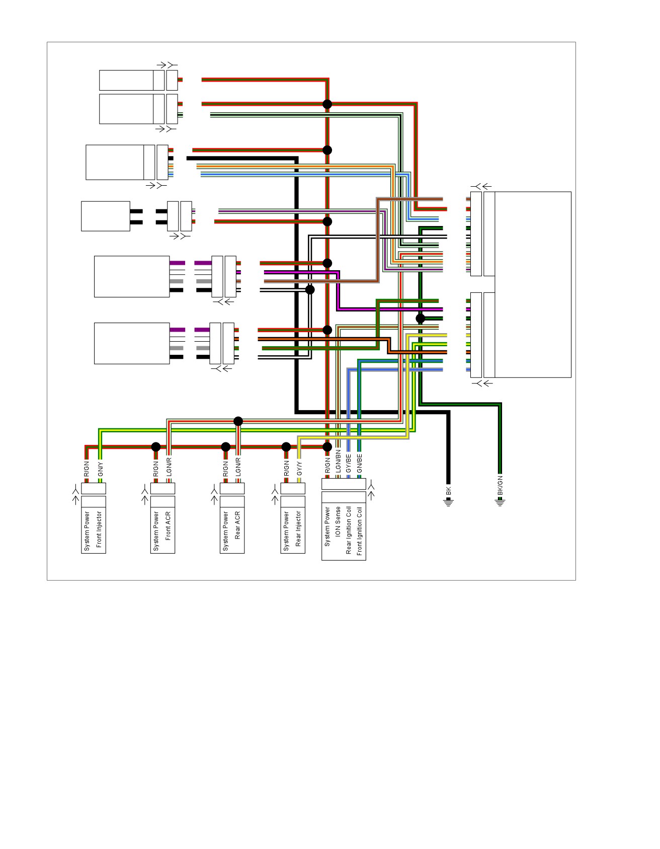
Figure 6-21. System Power Circuit
6-42 2013 Softail Diagnostics: Engine Management

HOME
DTC P0261
4. Injector Resistance Test
1. Using HARNESS CONNECTOR TEST KIT (Part No. HD-
PART NUMBER
TOOL NAME
41404), test resistance between [84A] terminals A (R/GN)
HD-34730-2E
FUEL INJECTOR TEST LIGHT
wire and B (GN/Y) wire.
HD-41404
HARNESS CONNECTOR TEST KIT
2. Is resistance between 10-20 Ohms?
HD-50390-1
BREAKOUT BOX
a. Yes. Replace ECM.
HD-50390-4
ECM CABLE
b. No. Replace front injector.
HD-50390-4-P
ECM OVERLAY
5. Driver Short to Ground Test
1. Remove fuel injector test light.
Table 6-35. DTC P0261 Diagnostic Faults
2. Using HARNESS CONNECTOR TEST KIT (Part No. HD-
POSSIBLE CAUSES
41404), test continuity between BOB [84A] terminal B and
ground.
Front fuel injector malfunction
Open signal circuit
3. Is continuity present?
Open power circuit
a. Yes. Repair short to ground on (GN/Y) wire.
b. No. Replace ECM.
1. Front Fuel Injector Test
1. Turn IGN OFF.
DTC P0262
2. Disconnect front fuel injector [84].
PART NUMBER
TOOL NAME
3. Connect FUEL INJECTOR TEST LIGHT (Part No. HD-
HD-41404
HARNESS CONNECTOR TEST KIT
34730-2E) to [84B].
4. Crank engine.
Table 6-36. DTC P0262 Diagnostic Faults
5. Does light flash when engine is cranking (or running)?
POSSIBLE CAUSES
a. Yes. Go to Test 4.
Front fuel injector malfunction
b. No, lamp does not illuminate. Go to Test 2.
Short to ground in signal circuit
c. No, lamp is on steady. Go to Test 5.
1. Front Fuel Injector Control Circuit Shorted
2. Power Circuit Open Test
to Voltage Test
1. Turn IGN OFF.
1. Turn IGN OFF.
2. Remove fuel injector test light.
2. Disconnect front injector [84].
3. Connect BREAKOUT BOX (Part No. HD-50390-1) and
3. Turn IGN ON.
ECM CABLE (Part No. HD-50390-4) to wiring harness
[78B-1] and [78B-2], leaving ECM [78A-1] and [78A-2]
4. Using HARNESS CONNECTOR TEST KIT (Part No. HD-
disconnected. See 1.2 DIAGNOSTIC TOOLS.
41404), test voltage between [84B] terminal B (GN/Y) wire
and ground.
4. Verify ECM OVERLAY (Part No. HD-50390-4-P) is in
position on BOB.
5. Is voltage less than 5.0V?
5. Using HARNESS CONNECTOR TEST KIT (Part No. HD-
a. Yes. Go to Test 3.
41404), test continuity between BOB [78-2] terminal 16
b. No. Go to Test 2.
and [84B] terminal A (R/GN) wire.
6. Is continuity present?
2. Control Circuit Shorted to System Test
a. Yes. Go to Test 3.
1. Turn IGN OFF.
b. No. Repair open in (R/GN) wire.
2. Test continuity between [84B] terminals A (R/GN) wire
and B (GN/Y) wire.
3. Control Circuit Open Test
3. Is continuity present?
1. Test continuity between BOB [78-1] terminal 5 and [84B]
a. Yes. Repair short between (R/GN) and (GN/Y) wires.
terminal B (GN/Y) wire.
b. No. Repair short to voltage on (GN/Y) wire.
2. Is continuity present?
a. Yes. Go to Test 4.
3. Injector Resistance Test
b. No. Repair open in (GN/Y) wire.
1. Test resistance between [84A] terminals A (R/GN) wire
and B (GN/Y) wire.
2013 Softail Diagnostics: Engine Management 6-43
HOME
2. Is resistance between 10-20 Ohms?
2. Is continuity present?
a. Yes. Replace ECM.
a. Yes. Go to Test 4.
b. No. Replace front injector.
b. No. Repair open in (GY/Y) wire.
DTC P0264
4. Injector Resistance Test
1. Using HARNESS CONNECTOR TEST KIT (Part No. HD-
PART NUMBER
TOOL NAME
41404), test resistance between [85A] terminal A and B
HD-34730-2E
FUEL INJECTOR TEST LIGHT
of injector [85A].
HD-41404
HARNESS CONNECTOR TEST KIT
2. Is resistance between 10-20 Ohms?
HD-50390-1
BREAKOUT BOX
a. Yes. Replace ECM.
HD-50390-4
ECM CABLE
b. No. Replace rear injector.
HD-50390-4-P
ECM OVERLAY
5. Driver Short to Ground Test
1. Remove fuel injector test light.
Table 6-37. DTC P0264 Diagnostic Faults
2. Using HARNESS CONNECTOR TEST KIT (Part No. HD-
POSSIBLE CAUSES
41404), test continuity between BOB [85B] terminal B and
ground.
Rear fuel injector malfunction
Open signal circuit
3. Is continuity present?
Open power circuit
a. Yes. Repair short to ground on (GY/Y) wire.
b. No. Replace ECM.
1. Rear Fuel Injector Test
1. Turn IGN OFF.
DTC P0265
2. Disconnect rear fuel injector [85].
PART NUMBER
TOOL NAME
3. Connect FUEL INJECTOR TEST LIGHT (Part No. HD-
HD-41404
HARNESS CONNECTOR TEST KIT
34730-2E) to [85B].
4. Crank engine.
Table 6-38. DTC P0265 Diagnostic Faults
5. Does lamp flash when engine is cranking (or running)?
POSSIBLE CAUSES
a. Yes. Go to Test 4.
Rear fuel injector malfunction
b. No, lamp does not illuminate. Go to Test 2.
Short to ground in signal circuit
c. No, lamp is on steady. Go to Test 5.
1. Rear Fuel Injector Control Circuit Shorted
2. Power Circuit Open Test
to Voltage Test
1. Turn IGN OFF.
1. Turn IGN OFF.
2. Remove fuel injector test light.
2. Disconnect rear injector [85].
3. Connect BREAKOUT BOX (Part No. HD-50390-1) and
3. Turn IGN ON.
ECM CABLE (Part No. HD-50390-4) to wiring harness
[78B-1] and [78B-2], leaving ECM [78A-1] and [78A-2]
4. Using HARNESS CONNECTOR TEST KIT (Part No. HD-
disconnected. See 1.2 DIAGNOSTIC TOOLS.
41404), test voltage between [85B] terminal B (GY/Y) wire
and ground.
4. Verify ECM OVERLAY (Part No. HD-50390-4-P) is in
position on BOB.
5. Is voltage less than 5.0V?
5. Using HARNESS CONNECTOR TEST KIT (Part No. HD-
a. Yes. Go to Test 3.
41404), test continuity between BOB [78-2] terminal 16
b. No. Go to Test 2.
and [85B] terminal A (R/GN) wire.
6. Is continuity present?
2. Control Circuit Shorted to System Test
a. Yes. Go to Test 3.
1. Turn IGN OFF.
b. No. Repair open in (R/GN) wire.
2. Test continuity between [85B] terminals A (R/GN) wire
and B (GY/Y) wire.
3. Control Circuit Open Test
3. Is continuity present?
1. Test continuity between BOB [78-1] terminal 6 and [85B]
a. Yes. Repair short between (R/GN) and (GY/Y) wires.
terminal B (GY/Y) wire.
b. No. Repair short to voltage on (GY/Y) wire.
6-44 2013 Softail Diagnostics: Engine Management
HOME
2. Is resistance between 10-20 Ohms?
3. Injector Resistance Test
a. Yes. Replace ECM.
1. Test resistance between [85A] terminals A (R/GN) wire
and B (GY/Y) wire.
b. No. Replace rear injector.
2013 Softail Diagnostics: Engine Management 6-45
HOME
DTC P0371,
P0372, P0374
6.12
DESCRIPTION AND OPERATION
ed03292
If the CKP sensor signal is weak or absent, DTCs P0371,
P0372 or P0374 will be set. DTC P0371 or P0372 is usually
2
set when several attempts to crank the engine have failed.
1
NOTE
If signal is not detected or cannot synchronize (DTC P0374),
engine will not start.
Table 6-39. Code Description
5
DTC
DESCRIPTION
3
P0371
Crank position sensor too many pulses
4
P0372
Crank position sensor too few pulses
P0374
Crank position sensor no pulses
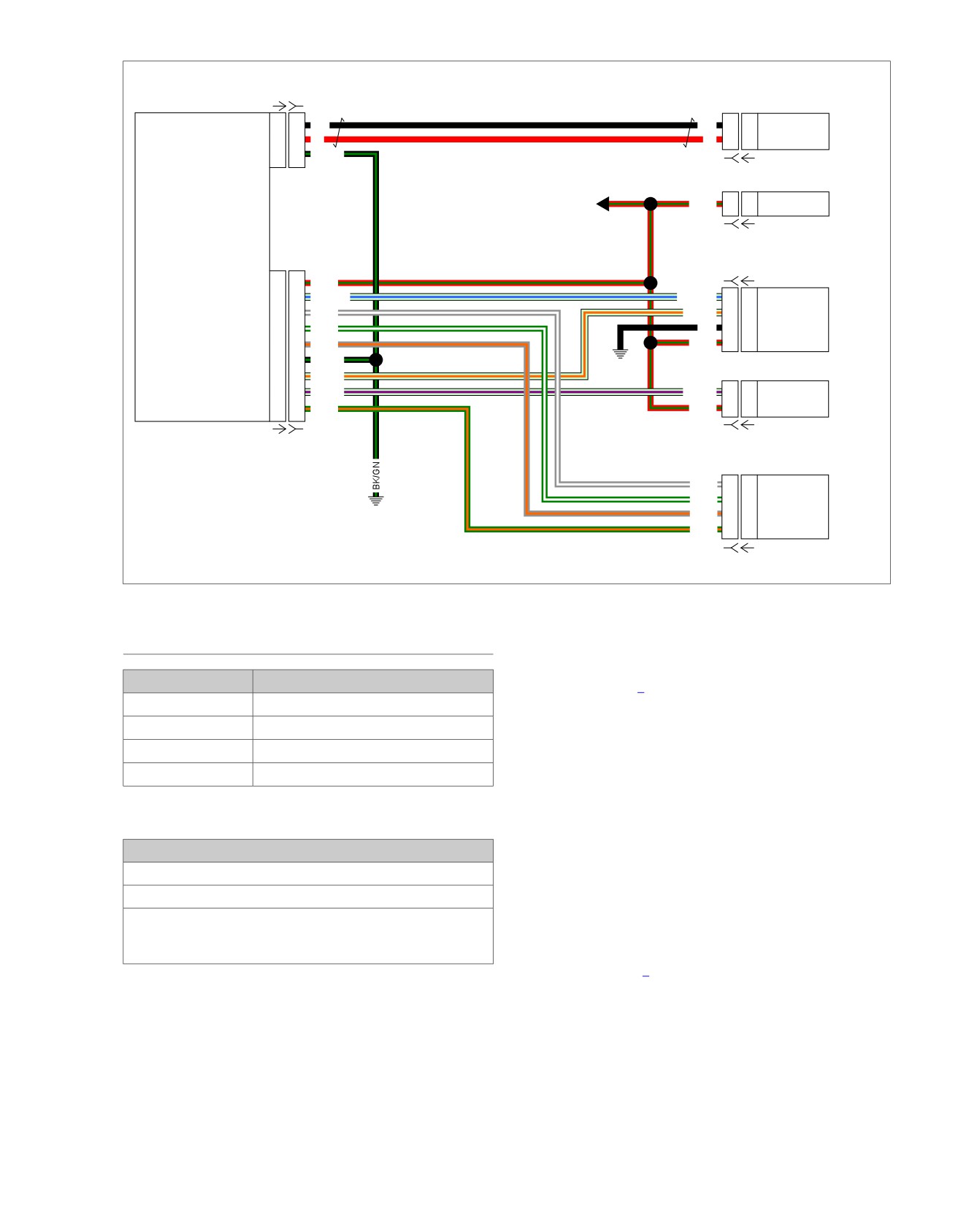
1. Voltage regulator to stator [47]
2. Front HO2 sensor [138]
Diagnostic Tips
3. Voltage regulator [77]
4. JSS [133]
Engine must be cranked for more than five seconds without
5. CKP sensor [79]
CKP signal to set P0374 code. Intermittent MAP or IAT wiring
or sensor issues may cause these codes to set prior to setting
Figure 6-22. Under Voltage Regulator
MAP or IAT codes. Verify MAP or IAT wiring and sensor prior
to replacing the ECM.
Connector Information
When disconnecting any connectors always inspect connector
for corrosion or backed out terminals and repair as required.
For additional information about the connectors in the following
diagram(s) and diagnostic procedure(s), including the color of
the harness test kit terminal probes, see B.1 CONNECTORS.
6-46 2013 Softail Diagnostics: Engine Management
HOME
em00995
[78A-1] [78B-1]
ECM
CKP Sensor Low
18
18
BK
BK
2
2
Sensor Low
CKP
CKP Sensor High
16
16
R
R
1
1
Sensor High
Ground
10
10
BK/GN
[79B] [79A]
Main
R/GN
L3
L3
System Power
BCM
Harness
[242B] [242A]
[179B] [179A]
System Power
16
16
R/GN
CKP Sensor Low
14
14
LGN/BE
LGN/BE
4
4
Feedback
CKP Sensor High
13
13
GY/W
LGN/O
3
3
Actuator
Exhaust
Actuator
IAC A High
12
12
GN/W
BK
2
2
Ground
(HDI)
IAC B Low
11
11
GY/O
R/GN
1
1
System Power
IAC A Low
10
10
BK/GN
GND 2
IAC B High
3
3
LGN/O
Ground
2
2
LGN/V
LGN/V
2
2
Active Intake
AIS
(HDI)
Ground
1
1
GN/O
R/GN
1
1
System Power
[178B] [178A]
[78A-2] [78B-2]
GY/W
A
A
B Low
GN/W
B
B
B High
IAC
GND 1
GY/O
C
C
A Low
GN/O
D
D
A High
[87B] [87A]
Figure 6-23. Active Exhaust Actuator and AIS Circuit
DTC P0371, P0372, P0374
4. Are terminal problems present?
a. Yes. Repair terminals as required.
PART NUMBER
TOOL NAME
b. No. Go to Test 2.
HD-41404
HARNESS CONNECTOR TEST KIT
2. Signal Wire Continuity Test
HD-50390-1
BREAKOUT BOX
1. Disconnect CKP sensor [79].
HD-50390-4
ECM CABLE
HD-50390-4-P
ECM OVERLAY
2. Connect BREAKOUT BOX (Part No. HD-50390-1) and
ECM CABLE (Part No. HD-50390-4) to wiring harness
[78B-1] and [78B-2], leaving ECM [78A-1] and [78A-2]
Table 6-40. DTC P0371, P0372, P0374 Diagnostic Faults
disconnected. See 1.2 DIAGNOSTIC TOOLS.
POSSIBLE CAUSES
3. Verify ECM OVERLAY (Part No. HD-50390-4-P) is in
position on BOB.
CKP sensor malfunction
4. Using HARNESS CONNECTOR TEST KIT (Part No. HD-
Open or short to ground in signal circuit
41404), test continuity between BOB [78-1] terminal 16 to
May be set if there are incorrect fluctuations from MAP that
[79B] terminal 1 (R) wire.
does not set MAP codes (examples - intermittent sensor or
wiring issue)
5. Is resistance less than 0.5 Ohm?
a. Yes. Go to Test 3.
1. CKP Sensor Connections Test
b. No. Repair open on (R) wire.
1. Turn IGN OFF.
2. Disconnect ECM [78-1] and [78-2].
3. Ground Wire Continuity Test
1. Test continuity between BOB [78-1] terminal 18 to [79B]
3. Inspect connection for corrosion or backed out terminals.
terminal 2 (BK) wire.
2013 Softail Diagnostics: Engine Management 6-47