Harley Davidson Softail Delux FLSTN BIKE 2011-2015. Electrical Diagnostics - page 11
HOME
ed03415
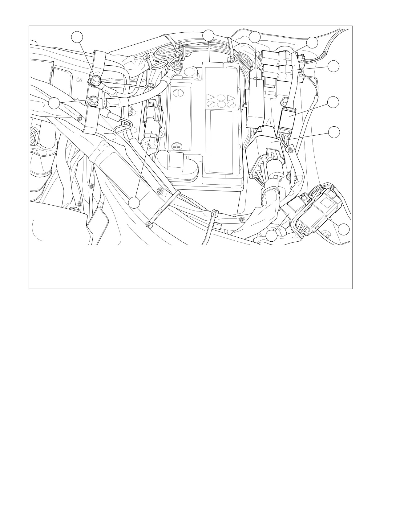
2
3
4
5
6
1
7
8
11
9
10
1. GND 1
7. Fuel pump/sender [13]
2. GND 2
8. Fuse block connector [64]
3. Resistor pack [200] (behind battery)
9. DLC [91]
4. Security antenna connector [209]
10. Left rear lighting [19]
5. Right rear lighting [18]
11. Rear HO2S [137]
6. Tail/LP lamp [45]
Figure 5-44. Under Seat: FXSB
5-66 2013 Softail Diagnostics: Accessories, Horn, Lighting and Security
HOME
ed03466
Table 5-58. Code Description
2
DTC
DESCRIPTION
B2176
Security antenna output open
B2177
Security antenna output shorted high
B2178
Security antenna output shorted low
Conditions for Setting
The BCM will recognize the faults with IGN ON.
Diagnostic Tips
•
Verify that cell phone is not within 3.0 in (80.0 mm) of key
fob.
1
•
Interference from physical surroundings impacts RF
transmission. Place fob next to vehicle or move vehicle to
a new location and retest.
•
See Figure 5-42. Verify that antenna is in OE location.
Make sure that seat has not been replaced with a metal
base seat.
•
Check for damage to antenna wire.
1.
Battery
2.
Fob serial number
•
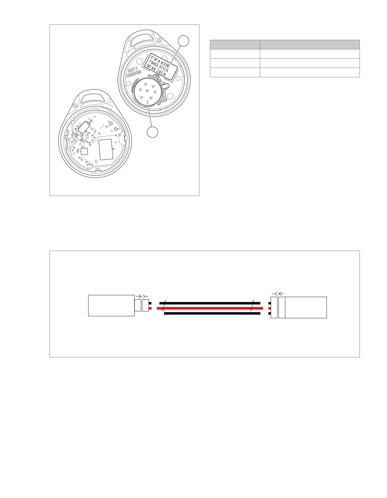
See Figure 5-45. Verify fob battery voltage is at least 2.9V.
Figure 5-45. Open Fob
•
Fob serial number is located inside fob. Twist thin blade
in thumbnail slot to open.
Connector Information
For additional information about the connectors in the following
diagram(s) and diagnostic procedure(s), including the color of
the harness test kit terminal probes, see B.1 CONNECTORS.
em00879
[208B] [208A]
[209A] [209B]
Security
Security Antenna Low
2
2
BK
BK
B2
B2
Security Antenna Low
Antenna
Security Antenna High
1
1
R
R
A2
A2
Security Antenna High
BCM
BK
A4
A4
Security RF Antenna
Figure 5-46. Antenna Circuit
2013 Softail Diagnostics: Accessories, Horn, Lighting and Security 5-67

HOME
DTC B2176
5. Antenna A Circuit Open Test
1. Test continuity between BOB terminal A2 and [209B] ter-
PART NUMBER
TOOL NAME
minal 1.
HD-41404
HARNESS CONNECTOR TEST KIT
2. Is continuity present?
HD-50390-1
BREAKOUT BOX
a. Yes. Go to Test 4.
HD-50390-2
BCM CABLE
b. No. Repair open in (R) wire.
HD-50390-2-P
BCM OVERLAY
6. DTC Test
1. Connect [242] and [209] (if needed).
Table 5-59. DTC B2176 Diagnostic Faults
2. Clear DTCs.
POSSIBLE CAUSES
3. Turn IGN ON.
Security antenna malfunction
Open antenna circuit
4. Check DTCs.
5. Did DTC reset?
1. Fob Test
a. Yes. Replace BCM.
1. Turn IGN OFF.
b. No. Concern is intermittent. See 1.3 DIAGNOSTICS
2. With fob present, turn IGN ON.
AND TROUBLESHOOTING, Wiggle Test.
3. Does odometer read ENTER PIN?
DTC B2177
a. Yes. Go to Test 2.
b. No. Go to Test 6.
PART NUMBER
TOOL NAME
HD-41404
HARNESS CONNECTOR TEST KIT
2. Security Antenna Visual Test
HD-50390-1
BREAKOUT BOX
1. Inspect the security antenna for damage.
HD-50390-2
BCM CABLE
2. Is the security antenna damaged?
HD-50390-2-P
BCM OVERLAY
a. Yes. Repair or replace security antenna as needed.
b. No. Go to Test 3.
Table 5-60. DTC B2177 Diagnostic Faults
3. Security Antenna Resistance Test
POSSIBLE CAUSES
1. Turn IGN OFF.
Security antenna malfunction
2. Disconnect antenna [209].
Short to voltage in antenna circuit
3. Using HARNESS CONNECTOR TEST KIT (Part No. HD-
1. Security Antenna Visual Test
41404), test resistance between terminals 1 and 2 of
[209A].
1. Inspect security antenna for damage.
4. Is resistance greater than 5700 Ohms?
2. Is the security antenna damaged?
a. Yes. Replace security antenna.
a. Yes. Repair or replace security antenna as needed.
b. No. Go to Test 2.
b. No. Go to Test 2.
4. Antenna B Circuit Open Test
2. Security Antenna High Circuit Short to
1. Connect BREAKOUT BOX (Part No. HD-50390-1) and
Voltage Test
BCM CABLE (Part No. HD-50390-2) to wire harness
1. Turn IGN OFF.
[242B], leaving
[242A] disconnected. See
1.2 DIA-
GNOSTIC TOOLS.
2. Connect BREAKOUT BOX (Part No. HD-50390-1) and
BCM CABLE (Part No. HD-50390-2) between wire harness
2. Verify BCM OVERLAY (Part No. HD-50390-2-P) is in
[242B] and [242A]. See 1.2 DIAGNOSTIC TOOLS.
position on BOB.
3. Verify BCM OVERLAY (Part No. HD-50390-2-P) is in
3. Test continuity between BOB terminal B2 and [209B] ter-
position on BOB.
minal 2.
4. Turn IGN ON.
4. Is continuity present?
5. Using HARNESS CONNECTOR TEST KIT (Part No. HD-
a. Yes. Go to Test 3.
41404), test voltage between BOB terminal A2 and ground.
b. No. Repair open in (BK) wire.
5-68 2013 Softail Diagnostics: Accessories, Horn, Lighting and Security

HOME
6. Is voltage greater than 0.6V?
3. Security Antenna Low Short to Ground
a. Yes. Repair short to voltage in (R) wire.
Test
b. No. Go to Test 3.
1. Test continuity between [209B] terminal 2 and ground.
2. Is continuity present?
3. Security Antenna Low Circuit Short to
a. Yes. Repair short to ground in (BK) wire.
Voltage Test
b. No. Go to Test 4.
1. Test voltage between BOB terminal B2 and ground.
2. Is voltage greater than 0.6V?
4. DTC Test
a. Yes. Repair short to voltage on (BK) wire.
1. Connect BCM [242] and [209].
b. No. Go to Test 4.
2. Clear DTC.
4. DTC Test
3. Turn IGN ON.
1. Clear DTCs.
4. Did the DTC return?
a. Yes. Replace BCM.
2. Turn IGN ON.
b. No. Concern is intermittent. See 1.3 DIAGNOSTICS
3. Check DTCs.
AND TROUBLESHOOTING, Wiggle Test.
4. Did DTC reset?
a. Yes. Replace BCM.
FAILS TO DISARM
b. No. Concern is intermittent. See 1.3 DIAGNOSTICS
PART NUMBER
TOOL NAME
AND TROUBLESHOOTING, Wiggle Test.
HD-41404
HARNESS CONNECTOR TEST KIT
DTC B2178
HD-50390-1
BREAKOUT BOX
HD-50390-2
BCM CABLE
PART NUMBER
TOOL NAME
HD-50390-2-P
BCM OVERLAY
HD-41404
HARNESS CONNECTOR TEST KIT
Table 5-62. Fails to Disarm Diagnostic Faults
Table 5-61. DTC B2178 Diagnostic Faults
POSSIBLE CAUSES
POSSIBLE CAUSES
Open antenna circuit
Security antenna malfunction
Short to ground in antenna circuit
Open antenna circuit
RF interference
1. Security Antenna Visual Test
Antenna malfunction
1. Inspect security antenna for damage.
Fob malfunction/dead battery
2. Is the security antenna damaged?
1. Non-Functional Fob Test
a. Yes. Repair or replace security antenna as needed.
1. Check battery on non-functional fob.
b. No. Go to Test 2.
2. Is battery voltage greater than 2.9V?
2. Security Antenna High Short to Ground
a. Yes. Go to Test 2.
Test
b. No. Replace battery. (6755)
1. Disconnect security antenna [209].
2. Interference Test
2. Turn IGN OFF.
1. Move vehicle away from any possible interference sources.
3. Disconnect BCM [242].
2. Place fob on seat.
4. Using HARNESS CONNECTOR TEST KIT (Part No. HD-
41404), test continuity between [209B] terminal 1 and
3. Will the security system disarm?
ground.
a. Yes. Inspect for electrical accessories or an after-
market seat that may be causing interference.
5. Is continuity present?
a. Yes. Repair short to ground in (R) wire.
b. No. Go to Test 3.
b. No. Go to Test 3.
3. Antenna Connection Test
1. Inspect antenna connection.
2013 Softail Diagnostics: Accessories, Horn, Lighting and Security 5-69
HOME
2. Is the antenna connection good?
2. Test continuity between BOB terminals A2 and B2.
a. Yes. Go to Test 4.
3. Is continuity present?
b. No. Repair connection.
a. Yes. Repair short between antenna circuits. (5041)
b. No. Go to Test 6.
4. Antenna Circuit Short to Ground Test
1. Turn IGN OFF.
6. Antenna Circuit Open Test
2. Connect the BREAKOUT BOX (Part No. HD-50390-1) and
1. Test continuity between BOB terminal A4 and end of (BK)
BCM CABLE (Part No. HD-50390-2) to wire harness
wire. Pull back conduit to expose unterminated end of
[242B], leaving BCM [242A] disconnected. See 1.2 DIA-
wire.
GNOSTIC TOOLS.
2. Is continuity present?
3. Verify BCM OVERLAY (Part No. HD-50390-2-P) is in
a. Yes. Go to Test 7.
position on BOB.
b. No. Repair open on (BK) wire. (5041)
4. Using HARNESS CONNECTOR TEST KIT (Part No. HD-
41404), test continuity between BOB terminal A4 and
7. Security System Antenna Test
ground.
1. Replace security antenna with a known good security
5. Is continuity present?
antenna.
a. Yes. Repair short to ground. (5041)
2. Does security system now disarm?
b. No. Go to Test 5.
a. Yes. Replace security antenna. (6878)
b. No. Replace BCM. (6757)
5. Antenna Circuits Shorted Together Test
1. Disconnect security antenna [209].
5-70 2013 Softail Diagnostics: Accessories, Horn, Lighting and Security
HOME
DTC B2183,
B2188, B2193, B2198
5.17
DESCRIPTION AND OPERATION
Conditions for Setting
These outputs are intended for future applications and are not
This output is shorted to ground in one of three areas:
used for this model.
•
Wire harness.
•
Device the output is connected to.
Table 5-63. Code Description
•
BCM.
DTC
DESCRIPTION
B2183
High side drive output #1 shorted low
Diagnostic Tips
B2188
High side drive output #2 shorted low
This circuit may be used for aftermarket accessories or sys-
tems. If a code is set and cannot be duplicated, check for
B2193
High side drive output #3 shorted low
aftermarket devices.
B2198
High side drive output #4 shorted low
Connector Information
For additional information about the connectors in the following
diagram(s) and diagnostic procedure(s), including the color of
the harness test kit terminal probes, see B.1 CONNECTORS.
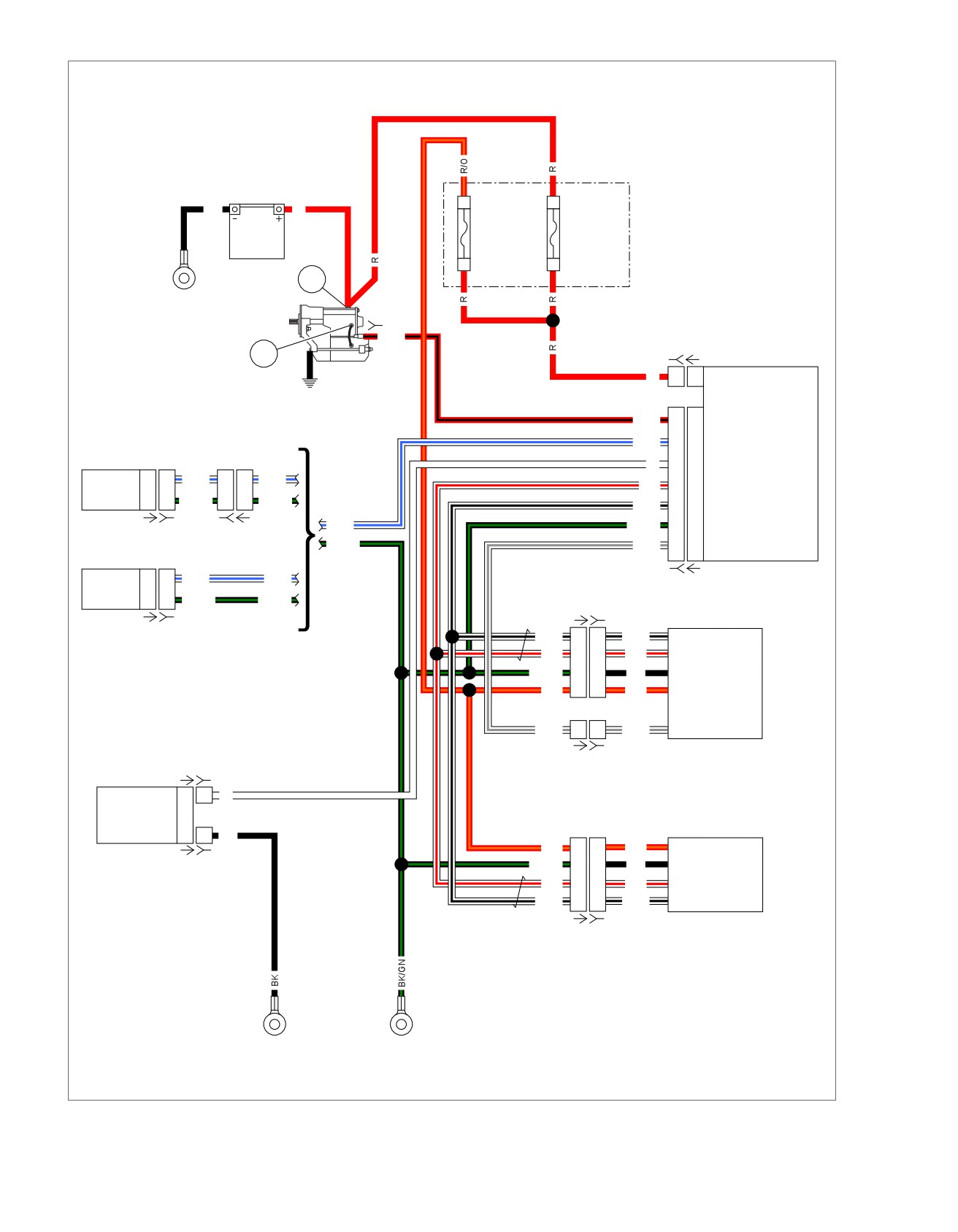
em01359
Fuse
B
Block
BK
R
Main
40A
A
Battery
[64B]
[128B]
GND 1
R/BK
[259B] [259A]
BCM
Starter
R
1
1
Battery Power
R/BK
L2
L2
Starter Solenoid Power
BK/GN
G4
G4
Ground
G2
G2
High Side Drive Output #1
G3
G3
High Side Drive Output #2
H4
H4
High Side Drive Output #3
H3
H3
High Side Drive Output #4
[242B] [242A]
GND 1
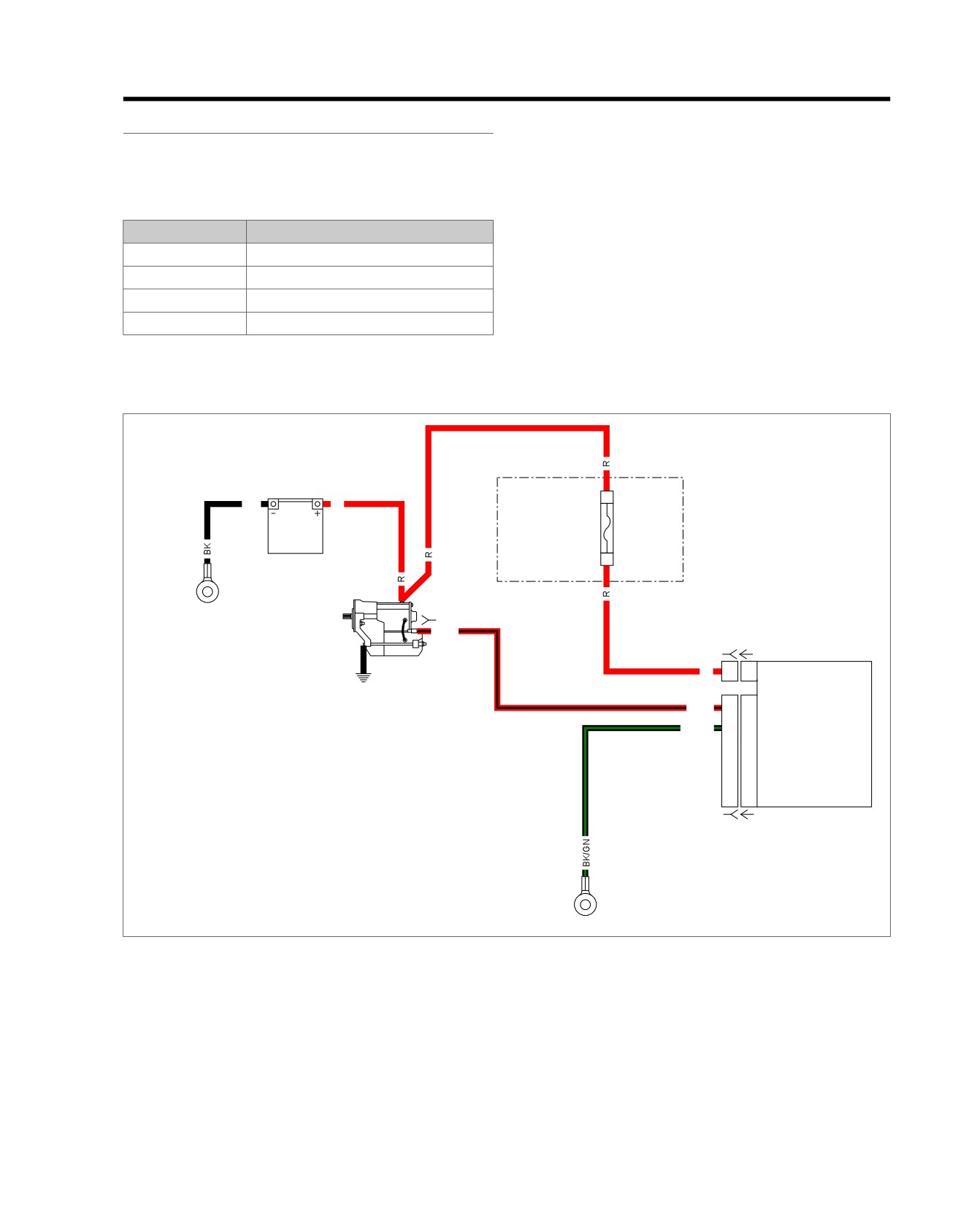
Figure 5-47. Spare Outputs
2013 Softail Diagnostics: Accessories, Horn, Lighting and Security 5-71
HOME
2. Are there wires plugged into any of the spare output ter-
DTC B2183, B2188, B2193, B2198
minals?
a. Yes. Problem may be caused by aftermarket devices.
Table 5-64. DTC B2183, B2188, B2193, B2198 Diagnostic
Refer to aftermarket manufacturer for repair.
Faults
b. No. Go to Test 2.
POSSIBLE CAUSES
Short to ground in spare output circuit
2. DTC Test
1. Clear DTCs.
1. Circuit Inspection Test
1. Visually inspect BCM harness [242].
2. Turn IGN ON.
3. Check DTCs.
4. Did DTC reset?
a. Yes. Replace BCM.
b. No. Concern is intermittent.
5-72 2013 Softail Diagnostics: Accessories, Horn, Lighting and Security
HOME
DTC B2218
5.18
DESCRIPTION AND OPERATION
ed03319
1
The BCM monitors the clutch and neutral switch circuits to
determine whether or not to let the vehicle start. No power will
be supplied to the starter solenoid unless either:
2
•
Clutch switch is closed (lever pulled in).
•
Neutral switch is closed (shifted to neutral).
Conditions for Setting
DTC B2218 will set when the neutral switch circuit is shorted
4
to ground at speeds greater than 5 mph (8 km/h) for more than
60 seconds.
3
Table 5-65. Code Description
DTC
DESCRIPTION
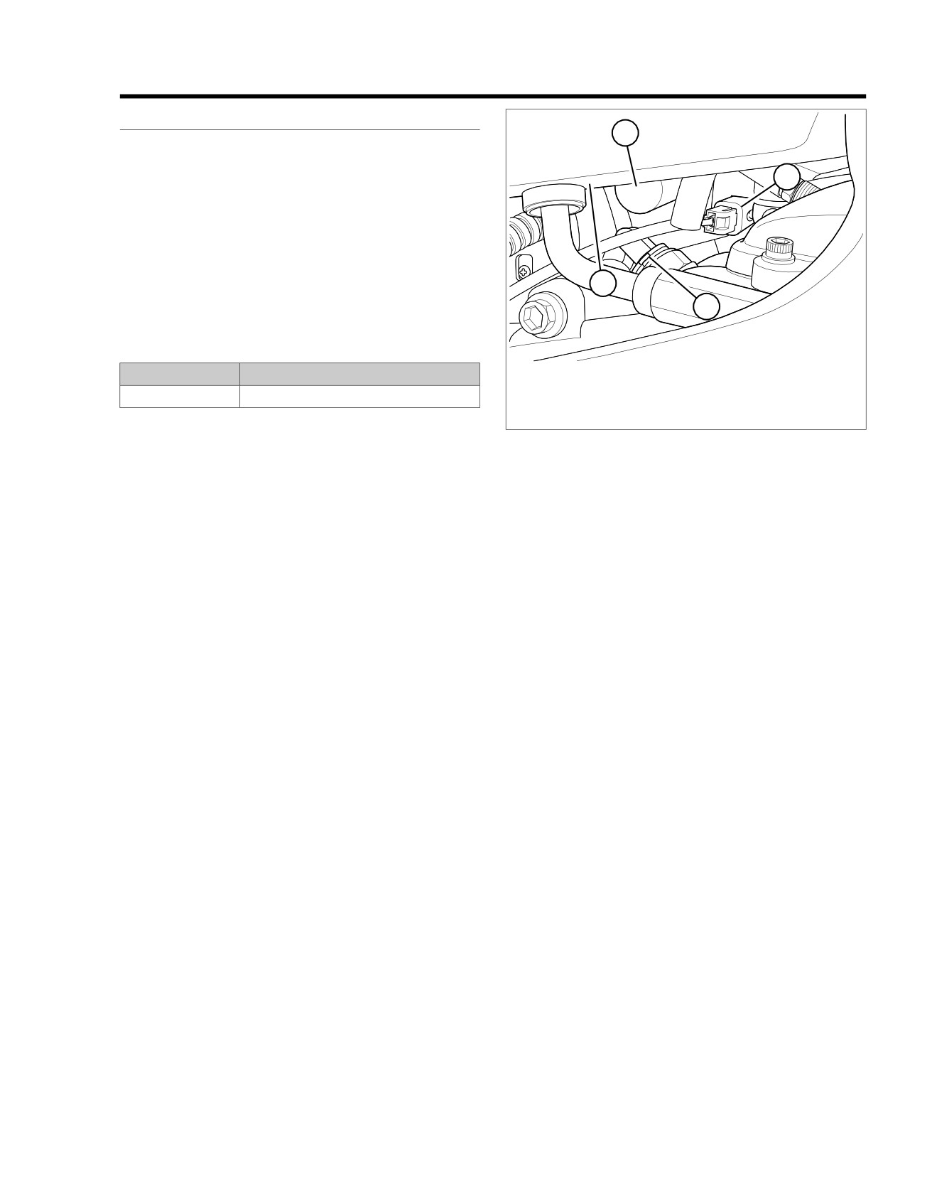
1. Starter
2. Starter solenoid [128]
B2218
Neutral switch shorted low
3. Neutral switch [131]
4. Oil tank
Connector Information
Figure 5-48. Under Oil Tank Right Side
For additional information about the connectors in the following
diagram(s) and diagnostic procedure(s), including the color of
the harness test kit terminal probes, see B.1 CONNECTORS.
2013 Softail Diagnostics: Accessories, Horn, Lighting and Security 5-73
HOME
em01524
Fuse
2
B
Block
BK
R
Battery
Main
15A
40A
1
A
Battery
[64B]
1
GND 1
[128B]
R/BK
[259B] [259A]
2
BCM
Starter
R
1
1
Battery Power
R/BK
L2
L2
Starter Solenoid Power
W/BE
C3
C3
Ignition Switch Input
Ignition
Switch
W
D3
D3
Neutral Switch Input
BCM Input
2
2
W/BE
5
5
W/BE
W/R
D2
D2
CAN High
(Except FXS/B)
Ground
1
1
BK/GN
2
2
BK/GN
W/BK
E2
E2
CAN Low
W/BE
BK/GN
G4
G4
Ground
[33A] [33B]
[20B] [20A]
BK/GN
W/GY
C4
C4
Engine Stop Switch Input
Ignition
Switch
BCM Input
2
2
W/BE
W/BE
[242B] [242A]
(FXS/B)
Ground
1
1
BK/GN
BK/GN
[22A-1] [22B-1]
[33A] [33B]
W/BK
4
4
W/BK
CAN Low
W/R
3
3
W/R
CAN High
Right
BK/GN
2
2
BK
Ground
Hand
R/O
1
1
R/O
Battery
Controls
W/GY
1
1
W/GY
Engine Stop Switch
[22A-2] [22B-2]
Neutral
[131A-1] [131B-1]
Switch
BCM Input
1
1
W
Ground
1
1
BK
R/O
1
1
R/O
Battery
[131A-2] [131B-2]
BK/GN
2
2
BK
Ground
Left
Hand
W/R
3
3
W/R
CAN High
Controls
W/BK
4
4
W/BK
CAN Low
[24A] [24B]
GND 2
GND 1
Figure 5-49. Starting Circuit
5-74 2013 Softail Diagnostics: Accessories, Horn, Lighting and Security
HOME
2. Is the neutral lamp illuminated?
DTC B2218
a. Yes. Go to Test 3.
PART NUMBER
TOOL NAME
b. No. Replace the neutral switch.
HD-41404
HARNESS CONNECTOR TEST KIT
3. Neutral Switch Short to Ground Test
HD-50390-1
BREAKOUT BOX
1. Turn IGN OFF.
HD-50390-2
BCM CABLE
HD-50390-2-P
BCM OVERLAY
2. Connect BREAKOUT BOX (Part No. HD-50390-1) and
BCM CABLE (Part No. HD-50390-2) to wire harness
[242B], leaving
[242A] disconnected. See
1.2 DIA-
Table 5-66. DTC B2218 Diagnostic Faults
GNOSTIC TOOLS.
POSSIBLE CAUSES
3. Verify BCM OVERLAY (Part No. HD-50390-2-P) is in
position on BOB.
Short to ground in neutral circuit
4. Using HARNESS CONNECTOR TEST KIT (Part No. HD-
Neutral switch malfunction
41404), test resistance between BOB terminal D3 and
ground.
NOTE
5. Is resistance less than 10 Ohms?
This DTC may occur if the vehicle is ridden in neutral at speeds
greater than 5 mph (8 km/h) for more than 60 seconds. For
a. Yes. Repair short to ground on (W) wire.
example, if coasting down a long mountain road with the
b. No. Go to Test 4.
transmission in neutral.
1. Neutral Circuit Short to Ground Test
4. DTC Test
1. Shift the transmission into 1st or 2nd gear.
1. Connect BCM [242] and neutral switch.
2. Turn IGN ON.
2. Clear DTC.
3. Is the neutral indicator illuminated?
3. Turn IGN ON.
a. Yes. Go to Test 2.
4. Operate vehicle above 5 mph (8 km/h) for at least two
minutes.
b. No. Verify neutral switch torque.
5. Did DTC return?
2. Neutral Switch Test
a. Yes. Replace BCM.
1. Disconnect the neutral switch [131-1].
b. No. Concern is intermittent. See 1.3 DIAGNOSTICS
AND TROUBLESHOOTING, Wiggle Test.
2013 Softail Diagnostics: Accessories, Horn, Lighting and Security 5-75
NOTES
5-76 2013 Softail Diagnostics: Accessories, Horn, Lighting and Security
TABLE OF CONTENTS
SUBJECT
PAGE NO.
6.1 EFI SYSTEM
6-1
6.2 ELECTRONIC CONTROL MODULE
6-3
6.3 SENSORS AND DRIVERS
6-5
6.4 DTC B2102, B2103, B2104
6-8
6.5 DTC B2116, B2117, B2118, B2119
6-13
6.6 DTC P0107, P0108
6-17
6.7 DTC P0112, P0113
6-21
6.8 DTC P0117, P0118
6-25
6.9 DTC P0122, P0123
6-29
6.10 DTC P0031, P0032, P0051, P0052, P0131, P0132, P0134, P0151, P0152, P0154
6-33
6.11 DTC P0261, P0262, P0264, P0265
6-41
6.12 DTC P0371, P0372, P0374
6-46
6.13 DTC P0444, P0445
6-49
6.14 DTC P0502, P0503
6-52
6.15 DTC P0506, P0507
6-56
6.16 DTC P0603, P0605
6-60
6.17 DTC P0641
6-61
6.18 DTC P0661, P0662
6-64
6.19 DTC P1009
6-67
6.20 DTC P1353, P1356
6-69
6.21 DTC P1475, P1478
6-72
6.22 DTC P1501, P1502
6-75
6.23 DTC P1632
6-79
6.24 DTC P1655, P1656
6-82
6.25 DTC P2300, P2301, P2303, P2304
6-86
6.26 ENGINE CRANKS, BUT WILL NOT START
6-90
6.27 HESITATION, LOSS OF POWER
6-92
6.28 STARTS, THEN STALLS
6-95
6.29 MISFIRE AT IDLE OR UNDER LOAD
6-98
NOTES
HOME
EFI SYSTEM
6.1
The ECM makes decisions for enabling ignition, starting, spark
GENERAL
and fuel delivery. Sensors include:
This chapter describes the operation of the Harley-Davidson
•
CKP sensor
EFI system. A good working knowledge of motorcycle com-
ponent is required for troubleshooting engine and EFI problems.
•
TPS
6.2 ELECTRONIC CONTROL MODULE and 6.3 SENSORS
•
JSS
AND DRIVERS briefly explain the operation of the ECM and
function of the various sensors and drivers. See 1.2 DIA-
•
BCM including an integrated accelerometer
GNOSTIC TOOLS for instructions on using the test equipment
•
Clutch switch
called out in the diagnostic test procedures in this chapter.
•
Neutral switch
The EFI system provides microprocessor-based electronic
engine management for the engine. The EFI system has the
•
ET sensor
following features:
•
VSS
•
Independently mapped spark and fuel control.
•
HO2 sensor
•
Compensated fuel delivery through engine temperature,
intake air temperature and manifold air pressure.
•
MAP
•
IAT sensor
•
Engine load measurement via throttle position sensing.
•
Single point spark delivery.
EFI Operation
•
Sequential port indirect (manifold) fuel injection.
The EFI system operates as an open or closed loop system,
allowing it to adjust for all possible operating conditions.
•
Open/closed loop air/fuel control.
•
During open loop operation, the system uses programmed
•
Automatic enrichment at start-up.
fuel and spark maps in the ECM providing easy cold
•
Engine speed and position determined by using a single
starting and maximum power at Wide Open Throttle
CKP sensor.
(WOT). The adaptive fuel value, learned during closed
loop operation, is applied to open loop operation to adjust
•
Engine idle speed electronically managed with an IAC
fuel and spark maps for optimal performance.
system.
•
During closed loop operation, the HO2 sensors provide
input for an optimal air/fuel mixture resulting in reduced
emissions, good fuel economy and smooth power. HO2
sensors must be at the normal operating temperature of
the engine.
By using both open and closed loop systems, engine perform-
ance is tuned. This compensates for change in conditions and
provides maximum performance. A simplified signal flow dia-
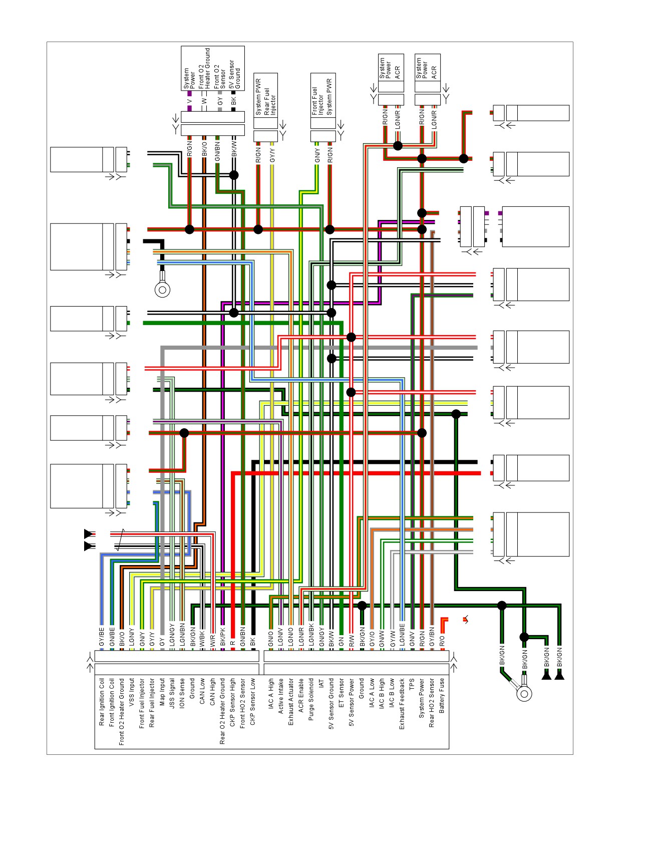
gram for the EFI system is shown in Figure 6-1.
Symptom Diagnostics
These sections contain diagnostic test procedures for DTCs
listed in 2.1 INITIAL DIAGNOSTICS. For symptoms of engine
malfunctions not specifically covered by DTCs, refer to
Table 6-1, Table 6-2 and Table 6-3.
2013 Softail Diagnostics: Engine Management 6-1
HOME
Front HO2
ACR
ACR
em00994
Sensor
Rear Fuel
Front Fuel
Injector
Injector
[203RA]
1
2
1
2
[203RA]
[203RB]
1
2
1
2
[203RB]
BCM
R/GN
L3
L3
System Power
[138A]
1
2
3
4
A
B
[85A]
B
A
[84A]
[138B]
1
2
3
4
A
B
[85B]
B
A
[84B]
[242B] [242A]
Purge
IAT
Solenoid
5V Sensor GND
2
2
BK/W
R/GN
A
A
System Power
IAT
1
1
GN/GY
LGN/BK
B
B
Purge Solenoid
[89A] [89B]
[95B] [95A]
Rear
HO2 Sensor
R/GN
1
1
V
System Power
Active Exhaust
BK/PK
2
2
W
Rear O2 Heater Ground
System Power
1
1
R/GN
3
3
GY/BN
GY
Rear O2 Sensor
Ground
2
2
BK
BK/W
4
4
BK
5V Sensor Ground
Exhaust Actuator
3
3
LGN/O
Exhaust
[137B] [137A]
4
4
LGN/BE
TPS
Feedback
R/W
1
1
5V Sensor PWR
[179A] [179B]
BK/W
2
2
5V Sensor GND
GN/V
3
3
TPS
ET Sensor
GND 2
5V Sensor GND
B
B
BK/W
[88B] [88A]
ET Sensor
A
A
GN
MAP Sensor
R/W
C
C
5V Sensor PWR
[90A] [90B]
GY
B
B
Map Input
JSS
BK/W
A
A
5V Sensor GND
5V Sensor PWR
1
1
R/W
[80B] [80A]
JSS Signal
2
2
LGN/GY
VSS
Ground
3
3
BK/GN
R/W
A
A
5V Sensor PWR
Active
LGN/Y
B
B
VSS Input
Intake
[133A] [133B]
BK/GN
C
C
Ground
Active Intake
2
2
LGN/V
System Power
1
1
R/GN
[65B] [65A]
CKP Sensor
Ignition
[178A] [178B]
Coil
BK
2
2
CKP Sensor Low
System Power
A
A
R/GN
CKP Sensor
R
1
1
High
ION Sense
B
B
LGN/BN
Rear Ignition Coil
C
C
GY/BE
[79B] [79A]
Front Ignition Coil
D
D
GN/BE
IAC
GN/O
D
D
IAC A High
[83A] [83B]
GY/O
C
C
IAC A Low
Main
W/R
GN/W
B
B
IAC B High
Harness
W/BK
GY/W
A
A
IAC B Low
[87B] [87A]
Battery
R/O
Fuse
[78B-1]
1
2
3
4
5
6
7
8
9
10 13 14 15 16 17 18
1
2
3
4
5
6
7
8
9
10 11 12 13 14 15 16 17 18
[78B-2]
[78A-1]
1
2
3
4
5
6
7
8
9
10 13 14 15 16 17 18
1
2
3
4
5
6
7
8
9
10 11 12 13 14 15 16 17 18
[78A-2]
Main
Harness
GND 1
ECM
Figure 6-1. EFI Simplified Schematic
6-2 2013 Softail Diagnostics: Engine Management
HOME
ELECTRONIC CONTROL MODULE
6.2
The front cylinder is fired every engine revolution. The ECM
GENERAL
monitors the power stroke after the fire event to determine if
See Figure 6-2 and Figure 6-3. The ECM receives and pro-
sufficient acceleration occurred to indicate the ECM fired on
cesses signals from the sensors and applies output signals to
the compression stroke. When two valid power strokes are
the drivers to crank, start, idle and run the engine. This section
detected, the ECM locks phase and resumes normal ignition
describes the configuration of the ECM.
events.
ECM
Engine Run Mode
The ECM is mounted under the seat. It computes the spark
Many functions of the EFI system require an engine run mode
advance for proper ignition timing and fuel control based on
determination. Engine run is determined by the level of engine
sensor inputs (from CKP, MAP and TPS sensors). The ECM
rpm. Generally, the engine is considered to be running when
controls the low-voltage circuits for the ignition coils and
engine rpm exceeds a minimum of 750 rpm.
injectors.
The ECM contains all of the components used in the ignition
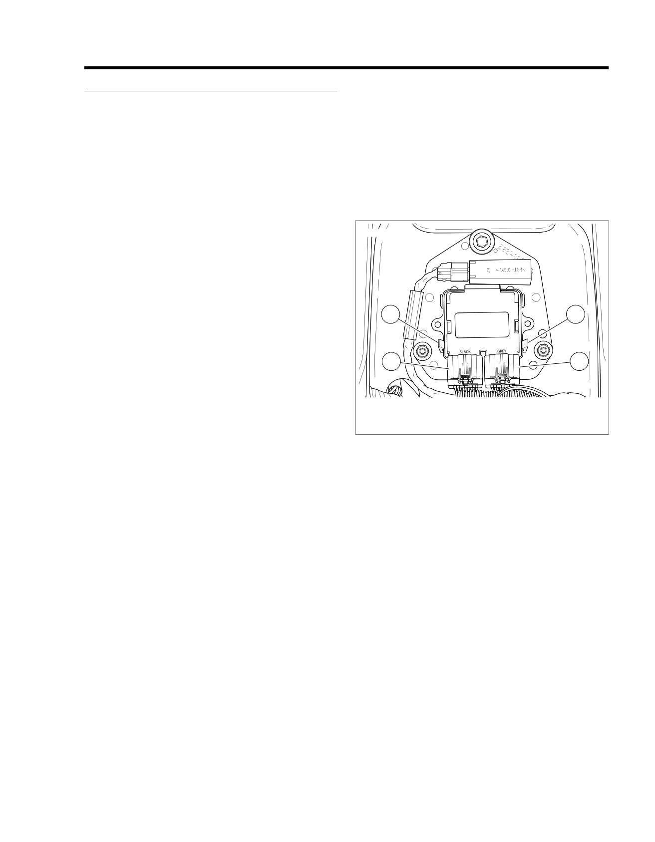
ed03469
system. The dwell time for the ignition coil is also calculated
in the microprocessor and is dependent upon battery voltage.
The programmed dwell provides adequate spark at all speeds.
(The ECM has protection against transient voltages, continuous
reverse voltage protection and damage due to jump starts.)
The ECM is fully enclosed to protect it from vibration, dust,
water or oil. This unit is a non-repairable item. If it fails, it must
3
3
be replaced.
32-2 Crankshaft
The crankshaft has 32 teeth evenly spaced around its circum-
1
2
ference with two consecutive teeth missing (sync gap). In this
configuration, the ECM determines engine position, engine
phase and engine speed from the CKP sensor input. Phase
(TDC compression) is determined by the ECM during startup
1. ECM [78-1]
and, when necessary, while running. No engine ignition events
2. ECM [78-2]
can occur until the ECM determines the relationship of piston
3. Retaining clips
position to crankshaft position. These continual ECM adjust-
Figure 6-2. ECM [78-1] and [78-2]: Except FXSB
ments allow smooth engine operation at all speeds.
Crank Position Signal Synchronization
In the 32-2 crank configuration, crankshaft position is determ-
ined by the ECM finding the two-tooth (sync gap) in the CKP
sensor signal. This is usually accomplished the first time the
sync gap is encountered. The ECM monitors the CKP signal
status every engine revolution. If the ECM determines synchron-
ization is lost, it immediately terminates ignition events and
synchronizes on the next occurrence of the sync gap.
Engine Phase
Phasing is accomplished by the ECM identifying a widening in
the CKP signal caused by the deceleration of the crankshaft,
as a piston approaches TDC on its compression stroke. Since
the rear cylinder approaches TDC earlier than the front cylinder,
engine phase can be readily discriminated. Phasing is normally
accomplished on the first TDC cycle after engine synchroniza-
tion. Once phased, the ECM can begin normal ignition events.
If the ECM experiences a system reset or loss of synchroniza-
tion while the engine is running it also loses phase.
When phase is lost one of the following occurs:
•
If an engine-not-running (crank mode) rpm is detected,
the ECM executes the normal start-up phasing process.
•
If engine run mode is detected, the ECM executes a run-
ning re-phase sequence.
2013 Softail Diagnostics: Engine Management 6-3
HOME
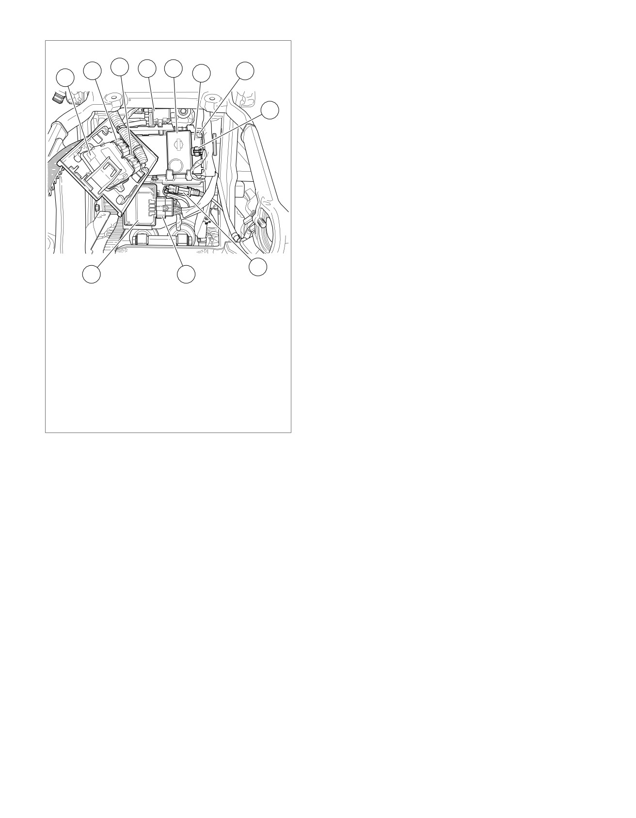
ed03462
3
4
5
2
7
6
1
8
9
11
10
1. ECM
2. ECM [78-2]
3. ECM [78-1]
4. Purge solenoid [95] (back side of purge
solenoid)
5. Security siren
6. BCM
7. BCM [242] (back side of BCM)
8. Security siren [142]
9. Rear WSS [168]
10. ABS [166]
11. ABS ECU
Figure 6-3. Electrical Panel: FXSB
6-4 2013 Softail Diagnostics: Engine Management
HOME
SENSORS AND DRIVERS
6.3
DESCRIPTION AND OPERATION
Neutral Switch
Sensors and drivers play an important part in the ECM's ability
The BCM provides voltage to the neutral switch, which is open
to provide the proper operational parameters for engine effi-
when the transmission is in gear. With the transmission in
ciency, emissions control and fuel economy. When a failure
neutral, the switch is closed, allowing current flow to ground.
occurs, a DTC is generated by, and stored in, the ECM or BCM.
The BCM will not allow the engine to start unless the transmis-
These codes help the technician diagnose engine trouble to
sion is in neutral or the clutch is pulled in.
the proper sensor or driver. See 2.1 INITIAL DIAGNOSTICS.
Engine Temperature (ET) Sensor
SENSORS
The ET sensor is a thermistor device. At a specific temperature
it has a specific resistance across its terminals. As this resist-
A failed CKP sensor completely disables the engine. Other
ance varies, so does the voltage.
sensor problems may cause engine performance issues or
complete engine shutdowns. The following are brief explana-
•
At high temperatures, the resistance of the sensor is very
tions of sensor types and their functions within the EFI system.
low. This effectively lowers the signal voltage on ECM [78-
2] terminal 8.
Crank Position (CKP) Sensor
•
At low temperatures, the resistance is very high, allowing
The CKP sensor, located on the left front of the lower crankcase
the voltage to rise close to 5V. The ECM monitors this
half, is a variable reluctance device that generates AC voltage
voltage to compensate for various operating conditions.
as the teeth on the crankshaft pass by the sensor. The signal
The ECM also uses the sensor input as a reference for
is routed to the ECM where it is used to determine crankshaft
determining Idle Air Control (IAC) pintle position.
position, engine speed (rpm) and engine phase (TDC compres-
sion). Without the presence of the CKP signal, the ECM will
Manifold Absolute Pressure (MAP) Sensor
not allow the ignition and fuel injection drivers to operate, and
thus the engine will not run. The ECM uses crankshaft com-
The MAP sensor is supplied 5V from the ECM and sends a
pression slow down events to determine engine phase.
signal back to the ECM. This signal changes with engine
Therefore, the spark plugs must be installed when checking
vacuum, intake air temperature and atmospheric barometric
for spark.
pressure. The MAP sensor monitors the intake manifold pres-
sure (vacuum) and sends the information to the ECM. The
Throttle Position Sensor (TPS)
ECM then adjusts the spark and fuel timing advance curves
for optimum performance. The sensor output determines if the
The TPS is a variable resistor (potentiometer) having a linear
engine is rotating when a fault with CKP sensor is present.
resistance range. It is mounted on the throttle plate. The output
of the sensor is a voltage dependent on the position of the
Intake Air Temperature (IAT) Sensor
throttle plate. The output is used by the ECM to determine
ignition timing and fuel required at any given rpm and engine
The IAT sensor is a thermistor device. At a specific temperature
load.
it has a specific resistance across its terminals. As the temper-
ature varies, the thermistor resistance varies and so does the
Jiffy Stand Sensor (JSS)
voltage on ECM [78-2] terminal 6.
The JSS uses a Hall-effect device to monitor jiffy stand position.
•
At high temperatures, the resistance of the sensor is very
When the jiffy stand is fully retracted, the sensor picks up the
low. This effectively lowers the signal voltage on ECM [78-
presence of a metal tab mounted to the jiffy stand. When
2] terminal 6.
extended, the engine only starts and runs if the ECM receives
•
At low temperatures, the resistance is very high, allowing
a signal from the neutral switch indicating the transmission is
the voltage to rise close to 5V. The ECM monitors this
in neutral, or a signal from the clutch switch indicating the clutch
voltage to compensate for various operating conditions.
is engaged. Otherwise, the engine stalls as the clutch is
released with the transmission in gear.
Vehicle Speed Sensor (VSS)
Accelerometer
The VSS is a Hall-effect device mounted close to the teeth of
the 5th gear in the transmission. The output signal frequency
The accelerometer is within the BCM. The BCM will shut the
varies with vehicle speed. The ECM processes the vehicle
engine down if the vehicle is tipped over. Once the sensor is
speed signal and transmits it via the CAN bus to the speedo-
tripped, the motorcycle must be righted, the ignition turned off
meter to indicate vehicle speed.
and then on again before the engine can be restarted. This is
communicated across the CAN communication.
Clutch Switch
The clutch switch is part of the left hand control module. Its
operation is communicated to the ECM and BCM over the CAN
communication circuits.
2013 Softail Diagnostics: Engine Management 6-5

HOME
See Figure 6-1. The BCM power a separate ignition coil for
HO2S: Front and Rear
each cylinder.
The HO2S detects unburned oxygen in the engine exhaust.
The output of the sensor is a voltage having a range of about
Fuel Injectors
0-1.0V.
The BCM provides battery power to the fuel injectors. The ECM
•
The normal output is 0.5V which represents a balance
provides the path to ground to trigger the injectors. The fuel
between a lean (not enough fuel) and rich (too much fuel)
injectors are pulse-width modulated solenoids for metering fuel
air/fuel mixture.
into the intake tract. The pulse-width of the ground path to the
injectors is varied by the ECM in response to inputs from the
•
An output less than 0.5V represents a lean mixture; greater
various sensors, thus varying the length of time the injector is
than 0.5V represents a rich mixture.
open.
•
The change in output level signals the ECM to modify the
Idle Air Control (IAC)
air/fuel ratio.
The IAC motor is a stepper-motor used to regulate the amount
The HO2S does not operate efficiently until the engine is at
of air entering the intake manifold during idle. The ECM controls
operating temperature. Always warm-up the vehicle prior to
engine idle speed by moving the IAC pintle to open or close a
troubleshooting the HO2S. The heater elements on the HO2S
passage around the throttle plate. It does this by sending
helps bring the HO2S up to operating temperature quicker.
voltage pulses to the proper motor winding of the IAC. This
Leaks in the exhaust system, leaky exhaust valves, misfires
causes the pintle to move in or out of the IAC a given distance
or any engine problem allowing unburned oxygen into the
for each pulse received.
exhaust stream could create a DTC indicating a bad sensor.
Look for problems related to an improper air/fuel mixture before
•
To increase idle speed, the ECM retracts the pintle,
replacing the sensor.
allowing more air to flow through the throttle body.
DRIVERS
•
To decrease idle speed, the ECM extends the pintle,
allowing less air to flow through the throttle body.
The ECM drivers are the output devices or system outputs of
the EFI system. Drivers are provided ground by the ECM to
Active Intake Solenoid (AIS): HDI Only
pump, inject and ignite the air/fuel mixture in the engine and
The AIS regulates the amount of air entering the air cleaner.
to activate relays.
The AIS opens when vehicle speed exceeds 45 mph (70 km/h)
Fuel Pump
with 50% or greater throttle opening. Once open, active intake
will close when vehicle speed falls below 40 mph (65 km/h).
The BCM provides battery voltage to the fuel pump which is
inside the fuel tank.
Active Exhaust Actuator: HDI Only
Ignition Coils and Spark Plugs
The active exhaust system utilizes an actuator valve located
in the rear exhaust pipe. This valve is connected to a servo
The ignition coils create the energy to fire the spark plugs and
motor via a cable. The valve position automatically adjusts to
ignite the air/fuel mixture in the cylinders. Advancing or
enhance engine performance.
retarding the spark is controlled by the ECM to suit load and
speed conditions of the engine.
Table 6-1. Engine Starts Hard
CAUSE
SOLUTION
Engine temperature circuit
Repair the circuit. If DTC P0117 or P0118 is present, diagnose and correct DTCs.
Fuel or Ignition system fault
Perform misfire diagnostics.
Battery discharged
Charge and test the battery. Perform charging system diagnosis if problem continues.
Crank position sensor circuit
Repair the circuit. If DTC P0371, P0372 or P0374 is present, diagnose and correct
DTC.
Manifold leak
Perform intake leak test.
Ignition coil circuit/spark plugs
Repair the circuit. If DTC P1353, P1356, P2300, P2301, P2303 or P2304 is present,
diagnose and correct DTCs.
Leaky injectors
Check for mechanical failures of the fuel injectors. If DTC P0261, P0262, P0264 or
P0265 is present, diagnose and correct them.
Valve sticking
Perform compression test.
6-6 2013 Softail Diagnostics: Engine Management

HOME
Table 6-2. Engine Performance Problems
CAUSE
SOLUTION
Engine temperature circuit
Repair the circuit. If DTC P0117 or P0118 are present, diagnose and correct DTCs.
Crank position sensor circuit
Repair the circuit. If DTC P0371, P0372 and P0374 are present, diagnose and correct
DTC.
Fuel or ignition system fault
Perform misfire diagnostics.
Manifold leak
Perform intake leak test.
Note: If manifold leak is large enough, the
IAC closes and sets a DTC.
Clogged fuel injectors
Clean or replace fuel injectors.
Throttle plates not opening fully
Perform throttle cable adjustment.
Fuel system contaminated
Drain and refill with fresh fuel.
Table 6-3. Engine Emits Black Exhaust or Fouls Plugs
CAUSE
SOLUTION
Engine temperature circuit
Repair the circuit. If DTC P0117 or P0118 are present, diagnose and correct DTCs.
Clogged air filter
Replace air filter.
Leaky injectors
Repair the circuit. If DTC P0261, P0262, P0264 or P0265 are present, diagnose and
correct DTCs.
IA
T sensor circuit
Repair the circuit. If DTC P0112 or P0113 are present, diagnose and correct DTCs.
2013 Softail Diagnostics: Engine Management 6-7