Harley Davidson Softail Delux FLSTN BIKE 2011-2015. Electrical Diagnostics - page 10
HOME
em01523
Front Left
Front Right
Running Light
Running Light
Left Turn
Right Turn
BCM
LHCM
Signal
Signal
RHCM
Switch
Switch
Not
[24B]
3
4
Used
D2
E2
J3
L4
M2
[242A]
3
4
[22B-1]
[24A]
3
4
3
4
[31A]
D2
E2
J3
L4
M2
[242B]
3
4
[22A-1]
R/Y
DLC
Resistor
BE
(HDI)
Assembly
Position
Lamp
BK
4
4
BK
1
1
BK
BE/BK
1
1
O/W
1
1
BK
[38A] [38B]
GND 2
1
4
[19A]
1
3
[40A]
1
4
[18A]
FXS/B
FLS
1
3
[40B]
FXS/B
FLS
1
4
[19B]
1
4
[19B]
1
4
[18B]
1
4
[18B]
Stop/Tail/
Rear Left
Rear Right
LP Lamp
STT
STT
(Canada)
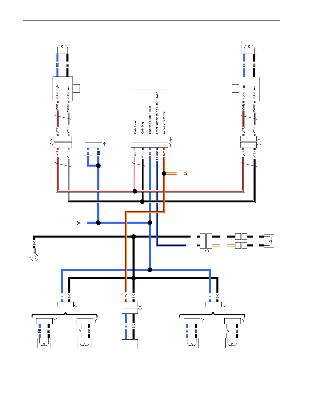
Figure 5-34. Running Lamps: FXS/B and FLS
5-46 2013 Softail Diagnostics: Accessories, Horn, Lighting and Security
HOME
FRONT RUNNING LAMPS INOPERATIVE
REAR RUNNING LAMPS INOPERATIVE:
EXCEPT FXS/B AND FLS
PART NUMBER
TOOL NAME
HD-41404
HARNESS CONNECTOR TEST KIT
PART NUMBER
TOOL NAME
HD-41404
HARNESS CONNECTOR TEST KIT
Table 5-42. Front Running Lamps Inoperative Diagnostic
Faults
Table 5-43. Rear Running Lamps Inoperative Diagnostic
Faults: Except FXS/B and FLS
POSSIBLE CAUSES
Open running lights circuit
POSSIBLE CAUSES
Lamp malfunction
Open running lights circuit
Open ground circuit
Lamp malfunction
Open ground circuit
NOTE
This test refers to domestic running lamps integrated with the
1. Running Lamps Configuration Test
front turn signals.
1. Inspect rear running lamps.
1. Domestic Running Lamp Configuration
2. Do rear turn signals also function as the brake lamps?
Test
a. Yes. Go to Test 4.
1. Inspect front running lamps.
b. No. Go to Test 2.
2. Are running lamps wired directly to the LHCM and RHCM?
2. Bulb Test
a. Yes. Go to Test 2.
1. Inspect inoperative bulb and socket.
b. No. Go to Test 3.
2. Is bulb and socket good?
2. Bulb Test
a. Yes. Go to Test 3.
1. Inspect inoperative bulb and socket.
b. No. Replace bulb. (6796)
2. Is bulb and socket good?
3. Ground Circuit Test
a. Yes. Replace LHCM or RHCM for the inoperative
1. Turn IGN OFF.
lamp. (6165) or (6166)
2. Using HARNESS CONNECTOR TEST KIT (Part No. HD-
b. No. Replace bulb. (6796)
41404), test continuity between tail lamp bulb socket ter-
minal ground and ground.
3. Running Lamp Test
1. Inspect inoperative bulb.
3. Is continuity present?
a. Yes. Repair open in running lamp power circuit.
2. Is bulb good?
(5041)
a. Yes. Go to Test 4.
b. No. Repair open in ground circuit (BK) wire. (5041)
b. No. Replace bulb. (6796)
4. Running Lamps Power Test
4. Ground Circuit Test
1. Disconnect rear lighting harness [7].
1. Turn IGN OFF.
2. Turn IGN ON.
2. Using HARNESS CONNECTOR TEST KIT (Part No. HD-
41404), test continuity between running lamp bulb socket
3. Using HARNESS CONNECTOR TEST KIT (Part No. HD-
ground and ground.
41404), test voltage between [7A] terminal 7 and ground.
3. Is continuity present?
4. Is voltage present?
a. Yes. Repair open in running lamp power circuit (BE)
a. Yes. Go to Test 5.
wire. (5041)
b. No. Repair open in (BE) wire. (5041)
b. No. Repair open in (BK) ground circuit. (5041)
5. Rear Running Lamps Ground Circuit Test
1. Turn IGN OFF.
2. Test continuity between ground and [7A] terminal 4, ter-
minal 5 and terminal 8.
2013 Softail Diagnostics: Accessories, Horn, Lighting and Security 5-47
HOME
3. Is continuity present on all three terminals?
2. Do rear turn signals function as brake lamps?
a. Yes. Replace rear lighting harness. (6823)
a. Yes. Go to Test 4.
b. No. Repair open in (BK) ground circuit. (5041)
b. No. Go to Test 2.
REAR RUNNING LAMPS INOPERATIVE:
2. Bulb Test
FXS/B AND FLS
1. Inspect inoperative bulb.
2. Is bulb good?
PART NUMBER
TOOL NAME
a. Yes. Go to Test 3.
HD-41404
HARNESS CONNECTOR TEST KIT
b. No. Replace bulb. (6796)
Table 5-44. Rear Running Lamps Inoperative Diagnostic
3. Ground Circuit Test
Faults: FXS/B and FLS
1. Turn IGN OFF.
POSSIBLE CAUSES
2. Using HARNESS CONNECTOR TEST KIT (Part No. HD-
Open running lights circuit
41404), test continuity between tail lamp bulb socket ter-
minal ground and ground.
Lamp malfunction
Open ground circuit
3. Is continuity present?
a. Yes. Repair open in running lamp power circuit.
1. Bulb Test
(5041)
1. Inspect inoperative bulb.
b. No. Repair open in ground circuit (BK) wire. (5041)
2. Is bulb good?
4. License Plate Lamps Power Test
a. Yes. Go to Test 2.
1. Turn IGN OFF.
b. No. Replace bulb. (6796)
2. Disconnect rear lighting harness [7].
2. Ground Circuit Test
3. Turn IGN ON.
1. Turn IGN OFF.
4. Using HARNESS CONNECTOR TEST KIT (Part No. HD-
2. Using HARNESS CONNECTOR TEST KIT (Part No. HD-
41404), test voltage between [7A] terminal 2 (R/Y) wire to
41404), test continuity between tail lamp bulb socket ter-
ground.
minal ground and ground.
5. Is battery voltage present?
3. Is continuity present?
a. Yes. Go to Test 5.
a. Yes. Repair open in running lamp power circuit.
b. No. Repair open in (R/Y) wire. (5041)
(5041)
b. No. Repair open in ground circuit (BK) wire. (5041)
5. License Plate Lamp Ground Circuit Test
1. Test for continuity between ground and [7A] terminal 5
LICENSE PLATE LAMP INOPERATIVE:
(BK) wire.
EXCEPT FXS/B AND FLS
2. Is continuity present?
a. Yes. Replace rear lighting harness. (6823)
PART NUMBER
TOOL NAME
HD-41404
HARNESS CONNECTOR TEST KIT
b. No. Repair open in (BK) ground circuit. (5041)
Table 5-45. License Plate Lamp Inoperative Diagnostic
Faults: Except FXS/B and FLS
POSSIBLE CAUSES
Open running lights circuit
Lamp malfunction
Open ground circuit
1. Running Lamps Configuration Test
1. Inspect rear running lamps.
5-48 2013 Softail Diagnostics: Accessories, Horn, Lighting and Security
HOME
3. Is continuity present?
LICENSE PLATE LAMP INOPERATIVE:
a. Yes. Replace LP LED light assembly.
FXS/B AND FLS
b. No. Repair open in (BK) wire. (5041)
PART NUMBER
TOOL NAME
DTC B2107
HD-41404
HARNESS CONNECTOR TEST KIT
PART NUMBER
TOOL NAME
Table 5-46. License Plate Lamp Inoperative Diagnostic
HD-50390-1
BREAKOUT BOX
Faults: FXS/B and FLS
HD-50390-2
BCM CABLE
POSSIBLE CAUSES
HD-50390-2-P
BCM OVERLAY
Open running lights circuit
HD-50424
1.5 MM TERMINAL EXTRACTOR
Lamp malfunction
TOOL
Open ground circuit
LED malfunction
Table 5-47. DTC B2107 Diagnostic Faults
1. Verify Test
POSSIBLE CAUSES
1. Verify LP lamp is a LED.
Short to power in front position/running circuit
2. Is LP lamp a LED?
1. Position Lamp Circuit Test
a. Yes. Go to Test 4.
1. Turn IGN OFF.
b. No. Go to Test 2.
2. Disconnect BCM [242].
2. Bulb Test
3. Using
1.5 MM TERMINAL EXTRACTOR TOOL (Part
No. HD-50424), remove terminal L4 from [242B].
1. Inspect license plate lamp.
4. Connect BREAKOUT BOX (Part No. HD-50390-1) and
2. Is bulb good?
BCM CABLE (Part No. HD-50390-2) between wire harness
a. Yes. Go to Test 3.
[242B] and [242A]. See 1.2 DIAGNOSTIC TOOLS.
b. No. Replace bulb. (6796)
5. Verify BCM OVERLAY (Part No. HD-50390-2-P) is in
position on BOB.
3. Ground Circuit Test
6. Turn IGN ON.
1. Turn IGN OFF.
7. Test voltage between extracted terminal L4 and ground.
2. Using HARNESS CONNECTOR TEST KIT (Part No. HD-
41404), test continuity between license plate lamp bulb
8. Is voltage present?
socket terminal ground and ground.
a. Yes. Repair short to voltage in the front position/run-
ning circuit.
3. Is continuity present?
a. Yes. Repair open in running lamp power circuit.
b. No. Go to Test 2.
(5041)
2. DTC Test
b. No. Repair open in ground circuit (BK) wire. (5041)
1. Connect [242].
4. LED + [40] Test
2. Clear DTC.
1. Turn IGN OFF.
3. Turn IGN ON.
2. Disconnect rear lighting [40].
4. Check DTCs.
3. Turn IGN ON.
5. Did DTC reset?
4. Using HARNESS CONNECTOR TEST KIT (Part No. HD-
a. Yes. Replace BCM.
41404), test voltage between [40A] terminal 1 and ground.
b. No. Concern is not currently present.
5. Is battery voltage present?
a. Yes. Go to Test 5.
b. No. Repair open in (R/Y) wire. (5041)
5. LED - [40] Test
1. Turn IGN OFF.
2. Test continuity between [40A] terminal 3 and ground.
2013 Softail Diagnostics: Accessories, Horn, Lighting and Security 5-49
HOME
DTC B2108, B2109
DTC B2166 (DOMESTIC ONLY)
PART NUMBER
TOOL NAME
PART NUMBER
TOOL NAME
HD-50390-1
BREAKOUT BOX
HD-41404
HARNESS CONNECTOR TEST KIT
HD-50390-2
BCM CABLE
HD-50390-1
BREAKOUT BOX
HD-50390-2-P
BCM OVERLAY
HD-50390-2
BCM CABLE
HD-50390-2-P
BCM OVERLAY
Table 5-48. DTC B2108, B2109 Diagnostic Faults
Table 5-49. DTC B2166 Diagnostic Faults (Domestic Only)
POSSIBLE CAUSES
Short to ground in front position/running circuit
POSSIBLE CAUSES
High current in front position/running circuit
Open in running lights ground circuit
Accessory lighting overloading circuit
Open in runnings lights power circuit
Incorrect configuration (HDI only)
1. Position Lamp Circuit Short to Ground
Test
1. Running Lamp Operation Test
1. Turn IGN OFF.
1. Verify tail lamp/license plate lamp, fuel gauge and fork
mounted front running lamps are operational.
2. Disconnect BCM [242].
2. Are all lights on?
3. Disconnect position lamp and fender tip lamp (if equipped).
a. Yes. Replace BCM.
4. Connect BREAKOUT BOX (Part No. HD-50390-1) and
BCM CABLE (Part No. HD-50390-2) to wire harness
b. No, some of the lights are on. Go to Test 3.
[242B], leaving
[242A] disconnected. See
1.2 DIA-
c. No, all lights are inoperative: except FXS/B. Go to
GNOSTIC TOOLS.
Test 4.
5. Verify BCM OVERLAY (Part No. HD-50390-2-P) is in
d. No, all lights are inoperative: FXS/B. Go to Test 5.
position on BOB.
6. Test for continuity between BOB terminal L4 and ground.
2. Running Lamps Circuit Test
7. Is continuity present?
1. Turn IGN OFF.
a. Yes. Repair short to ground in (BE/BK) wire.
2. Disconnect rear lighting harness [7].
b. No. Go to Test 2.
3. Turn IGN ON.
4. Using HARNESS CONNECTOR TEST KIT (Part No. HD-
2. Excessive Draw Test
41404), test voltage between [7A] terminal 7 and ground.
1. Remove accessory lighting (if equipped). Unplug one lamp
5. Is battery voltage present?
at a time on circuit and cycle IGN ON-OFF-ON.
a. Yes. Replace BCM.
2. Check DTCs after each lamp is removed.
b. No. Repair open in (BE) wire.
3. Does code clear?
a. Yes. Replace lamp that was causing issue.
3. Bulb Test
b. No. Go to Test 3.
1. Inspect inoperative bulb.
2. Is bulb good and the correct bulb?
3. DTC Test
a. Yes.
1. Turn IGN OFF.
b. No. Replace bulb.
2. Connect [242].
3. Clear DTC.
4. Running Lamp Open Circuit Test
1. Turn IGN OFF.
4. Turn IGN ON.
2. Disconnect BCM [242].
5. Check DTCs.
3. Connect BREAKOUT BOX (Part No. HD-50390-1) and
6. Did DTC reset?
BCM CABLE (Part No. HD-50390-2) to wire harness
a. Yes. Replace BCM.
[242B], leaving [242A] disconnected. See 2.1 INITIAL
b. No. Condition not currently present.
DIAGNOSTICS, Odometer Self-Diagnostics.
4. Verify BCM OVERLAY (Part No. HD-50390-2-P) is in
position on BOB.
5-50 2013 Softail Diagnostics: Accessories, Horn, Lighting and Security
HOME
5. Test continuity between BOB terminal J3 and inoperative
5. Did DTC return?
running lamp power circuit.
a. Yes, the front running lamps are wired to hand
control modules. Go to Test 4.
6. Is continuity present?
a. Yes. Replace bulb and socket.
b. Yes, the front running lamps are not wired to hand
control modules. Go to Test 3.
b. No. Repair open in running lamp circuit between
inoperative lamp and BCM.
c. No. Replace fuel gauge.
5. Running Lamps Circuit Test
3. Front Running Lamp Circuit Test
1. Turn IGN OFF.
1. Turn IGN OFF.
2. Disconnect left rear stop/tail/turn harness [19].
2. Disconnect front turn signal [31].
3. Turn IGN ON.
3. Clear DTC.
4. Using HARNESS CONNECTOR TEST KIT (Part No. HD-
4. Cycle IGN OFF-ON.
41404), test voltage between [19A] terminal 1 and ground.
5. Did DTC return?
5. Is battery voltage present?
a. Yes. Go to Test 4.
a. Yes. Replace BCM.
b. No. Repair short to ground in front running lamps
b. No. Repair open in (BE) wire.
harness.
DTC B2168, B2169
4. BCM Test
1. Turn IGN OFF.
PART NUMBER
TOOL NAME
2. Disconnect BCM [242].
HD-41404
HARNESS CONNECTOR TEST KIT
3. Connect BREAKOUT BOX (Part No. HD-50390-1) and
HD-50390-1
BREAKOUT BOX
BCM CABLE (Part No. HD-50390-2) to wire harness
HD-50390-2
BCM CABLE
[242B], leaving
[242A] disconnected. See
1.2 DIA-
GNOSTIC TOOLS.
HD-50390-2-P
BCM OVERLAY
4. Verify BCM OVERLAY (Part No. HD-50390-2-P) is in
position on BOB.
Table 5-50. DTC B2168, B2169 Diagnostic Faults
5. Using HARNESS CONNECTOR TEST KIT (Part No. HD-
POSSIBLE CAUSES
41404), test continuity between BOB terminal J3 and
Running lights circuit resistance too low
ground.
Short to ground in running lights power circuit
6. Is continuity present?
Accessory lighting overloading circuit
a. Yes. Repair short to ground in (BE) wire.
b. No. Replace BCM.
1. Rear Running Lamps Circuit Test
1. Turn IGN OFF.
DTC B2168, B2169: FXS/B AND FLS
2. Disconnect rear lighting [7].
PART NUMBER
TOOL NAME
3. Clear DTC.
HD-41404
HARNESS CONNECTOR TEST KIT
4. Cycle IGN OFF-ON.
HD-50390-1
BREAKOUT BOX
5. Did DTC return?
HD-50390-2
BCM CABLE
a. Yes. Go to Test 2.
HD-50390-2-P
BCM OVERLAY
b. No. Repair short to ground or high current draw in
rear lighting harness in the running lamp power cir-
cuits.
Table 5-51. DTC B2168, B2169 Diagnostic Faults: FXS/B
and FLS
2. Ground Circuit Open Test
POSSIBLE CAUSES
1. Turn IGN OFF.
Running lights circuit resistance too low
2. Disconnect fuel gauge [117].
Short to ground in running lights power circuit
3. Clear DTC.
Accessory lighting overloading circuit
4. Cycle IGN OFF-ON.
1. Right Rear Turn Lamp Circuit Test
1. Turn IGN OFF.
2013 Softail Diagnostics: Accessories, Horn, Lighting and Security 5-51
HOME
2. Disconnect right rear turn lamp [18].
5. Did DTC return?
a. Yes. Go to Test 4.
3. Clear DTC.
b. No. Repair short to ground or high current draw in tail
4. Cycle IGN OFF-ON.
lamp harness in the running lamp power circuits.
5. Did DTC return?
a. Yes. Go to Test 2.
4. Ground Circuit Open Test
b. No. Repair short to ground or high current draw in
1. Turn IGN OFF.
right rear turn signal harness in the running lamp
2. Disconnect the resistor assembly [200].
power circuits.
3. Clear DTC.
2. Left Rear Turn Lamp Circuit Test
4. Cycle IGN OFF-ON.
1. Turn IGN OFF.
5. Did DTC return?
2. Disconnect left rear turn lamp [19].
a. Yes. Go to Test 5.
3. Clear DTC.
b. No. Replace the resistor assembly.
4. Cycle IGN OFF-ON.
5. BCM Test
5. Did DTC return?
1. Turn IGN OFF.
a. Yes. Go to Test 3.
2. Disconnect BCM [242].
b. No. Repair short to ground or high current draw in left
rear turn signal harness in the running lamp power
3. Connect BREAKOUT BOX (Part No. HD-50390-1) and
circuits.
BCM CABLE (Part No. HD-50390-2) to wire harness
[242B], leaving
[242A] disconnected. See
1.2 DIA-
3. Tail Lamp Circuit Test
GNOSTIC TOOLS.
1. Turn IGN OFF.
4. Verify BCM OVERLAY (Part No. HD-50390-2-P) is in
position on BOB.
2. Disconnect tail lamp [40].
5. Using HARNESS CONNECTOR TEST KIT (Part No. HD-
3. Clear DTC.
41404), test continuity between BOB terminal J3 and
4. Cycle IGN OFF-ON.
ground.
6. Is continuity present?
a. Yes. Repair short to ground in (BE) wire.
b. No. Replace BCM.
5-52 2013 Softail Diagnostics: Accessories, Horn, Lighting and Security
HOME
SECURITY SYSTEM
5.11
ability to alternately flash the left and right turn signals and
SECURITY LAMP
sound a siren (if equipped) if a theft attempt is detected.
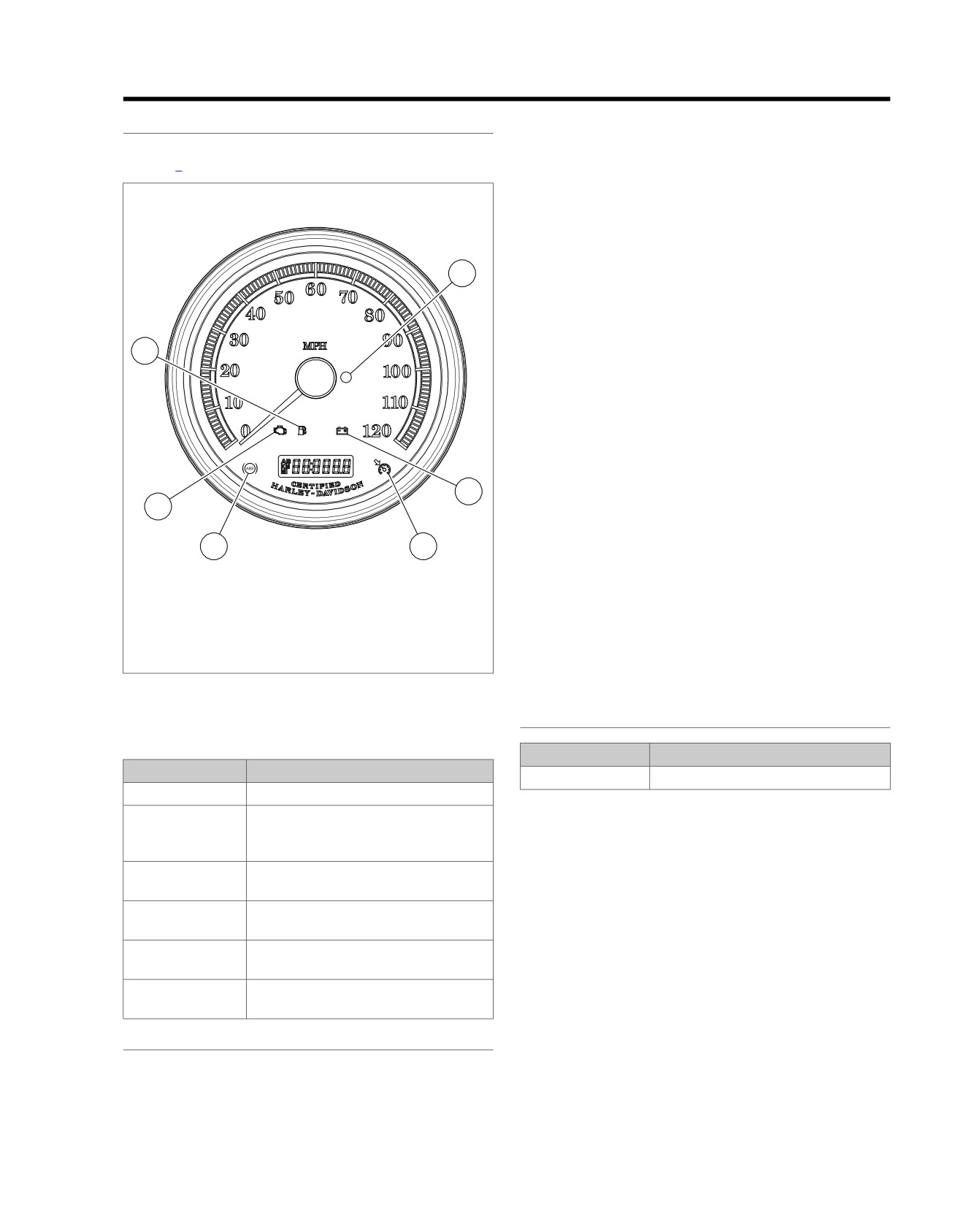
See Figure 5-35. The security lamp indicates system status.
NOTE
Refer to Table 5-52.
The siren must be in the chirp mode for the siren to chirp on
ed03268
arming or disarming. See 5.13 SIREN, Siren Chirp Mode
Confirmation.
Conditions that trigger a security event when system is armed
include:
4
•
Detecting tampering of the ignition circuit: Turn signals
flash three times, optional siren chirps once and then turns
off. If the tampering continues, a second warning will
activate after four seconds. Continued tampering will cause
the alarm to activate for 30 seconds and then turn off. The
3
two warnings/alarm cycle is repeated for each tampering
incident. The system will remain armed and the vehicle
will be immobilized.
•
Detecting vehicle movement: Turn signals flash three
times, optional siren chirps once and then turns off. If the
vehicle is not returned to its original position, a second
warning will activate after four seconds. If the vehicle is
5
not returned to its original position, the alarm activates for
2
30 seconds then turns off. The two warnings/alarm cycle
may repeat a maximum of 10 times with a 10 second
pause between cycles.
1
6
•
Detecting that a battery or ground disconnect has
1.
ABS lamp (if equipped)
occurred while armed: The optional siren activates its
2.
Check engine lamp
self-alarm mode. Turn signals will not flash.
3.
Low fuel lamp
4.
Security lamp
NOTE
5.
Battery
Always disarm the vehicle by turning the IGN ON with the fob
6.
Cruise enabled lamp (not used)
present before removing or disconnecting the battery. This
Figure 5-35. Indicator Lamps
prevents the siren (if installed) from activating.
SECURITY SYSTEM FEATURES
Table 5-52. Security Lamp Status
PART NUMBER
TOOL NAME
LAMP
MODE
HD-48650
DIGITAL TECHNICIAN II
Does not flash.
Security system not armed.
The following information applies only to vehicles equipped
Flashes every
Two minute timeout after failed PIN entry
second.
attempt or a battery reconnect has
with the security.
occurred while armed.
•
Personal code disarming: If the fob is not available or
Flashes every 2.5
Security system armed.
inoperative, the BCM allows the rider to disable the
seconds.
security alarm and immobilization functions with a five-
digit personal code.
Flashes 4 times a
PIN entry mode.
second.
•
Arming confirmation: When the security system is
armed, the system provides visual feedback (confirmation)
Stays on solid with
Arming is starting up. You have five
to the rider by flashing the turn signals and an audible
IGN OFF.
seconds before system is armed.
"chirp" if equipped with the optional smart siren and chirp
Stays on solid with
If solid for more than four seconds after
mode is enabled.
IGN ON.
IGN ON, a current DTC is present.
•
Disarming confirmation: When the security system is
SECURITY IMMOBILIZATION
disarmed, the system provides an audible "chirp" (confirm-
ation) if equipped with the optional smart siren and chirp
If the vehicle is equipped with the security system, the function-
mode is enabled.
ality is provided by a security BCM. The BCM will disable the
starter and ignition system. Additional functions include the
•
Transport mode: It is possible to arm the security system
without enabling the motion detector for one ignition cycle.
2013 Softail Diagnostics: Accessories, Horn, Lighting and Security 5-53
HOME
This allows the vehicle to be moved in an immobilized
On arming, the turn signals flash twice and the smart siren will
state.
"chirp" twice if chirp function is activated. While armed, the
security lamp will flash once every 2.5 seconds. Refer to
•
Starter/ignition disable: When armed the starter and
Table 5-52.
ignition system are disabled.
DISARMING
•
Security system alarm: See 5.13 SIREN. The system
will alternately flash the left and right turn signals and
There are two ways to disarm the H-DSSS:
sound an optional Smart Siren if a vehicle security condi-
•
Automatic disarming.
tion is detected while the system is armed.
•
Using the PIN.
•
Dealer service mode: This mode allows the dealer to
disable security system via DIGITAL TECHNICIAN II (Part
Automatic Disarming
No. HD-48650). Dealer service mode is exited when the
IGN is turned ON with the assigned fob in range.
Always have the fob present when riding, loading, fueling,
moving, parking or servicing the vehicle. Carry the fob in a
SECURITY SYSTEM WARNINGS
convenient pocket. The vehicle can be moved in an armed
state with the fob present without triggering the alarm. The H-
A warning consists of three alternate flashes of the turn signals
DSSS disarms automatically when the ignition switch is turned
and chirp from the optional smart siren. Warnings are issued
to ON.
from an armed security system in the following order:
On disarming, the smart siren will chirp once (if chirp function
1. First Warning: A warning is issued whenever a person
is activated) and the security lamp will turn ON solid for four
without a fob present or with the system armed attempts
seconds then go out. Refer to Table 5-52.
to move the vehicle or turns the ignition switch to IGN.
Disarming with a PIN
2. Second Warning: If the motion continues or the ignition
switch is not turned back to OFF, a second warning is
See 5.14 SERVICE AND EMERGENCY FUNCTIONS AND
issued within four seconds of the first.
CONFIGURATIONS to enter an initial PIN to enable the
system.
3. Alarm: If the motion continues or the ignition switch is not
turned to OFF past the second warning, the smart security
If you make an error while disarming the security system using
system will go into full alarm.
the PIN, the alarm will activate for 30 seconds after the last
digit is entered. After a failed attempt, the security lamp will
ARMING
flash once every second for two minutes. During this time,
the vehicle will not accept any attempt to enter a PIN. Refer
The H-DSSS automatically arms within five seconds when the
to Table 5-53.
vehicle is parked and the ignition switch is turned to OFF or
ACC and motion is not detected.
Table 5-53. Entering a PIN to Disarm Harley-Davidson Smart Security System
STEP
ACTION
WAIT FOR CONFIRMATION
NOTES
NO.
1
If necessary, verify the current 5-digit
Should be recorded on wallet card.
PIN.
2
Turn ignition to IGN.
If armed, the odometer window display
will read: ENTER PIN and the security
lamp will be flashing at a fast rate. The
headlight will not be on.
3
Press and release the left turn signal
In the odometer window, a flashing 1
switch.
will appear.
4
Increment the digit by tapping the left
The first digit in the odometer will be
turn signal until the odometer window
the first digit in the PIN.
displays the first digit of the PIN.
5
Press right turn switch 1 time.
The first digit is stored and the next
Serves as enter key.
digit will flash.
6
Increment the second digit using the
The second digit in the odometer will
left turn switch until the digit reaches
be the second digit in the PIN.
the second digit of the PIN.
7
Press right turn switch 1 time.
The second digit is stored and the
Serves as enter key.
next dash will flash.
8
Increment the third digit using the left
The third digit in the odometer will be
turn switch until it reaches the third
the third digit in the PIN.
digit of the PIN.
5-54 2013 Softail Diagnostics: Accessories, Horn, Lighting and Security
HOME
Table 5-53. Entering a PIN to Disarm Harley-Davidson Smart Security System
STEP
ACTION
WAIT FOR CONFIRMATION
NOTES
NO.
9
Press right turn switch 1 time.
The third digit is stored and the next
Serves as enter key.
dash will flash.
10
Increment the fourth digit using the
The fourth digit in the odometer will
left turn switch until it reaches the
be the fourth digit in the PIN.
fourth digit of the PIN.
11
Press right turn switch 1 time.
The fourth digit is stored and the next
Serves as enter key.
dash will flash.
12
Increment the fifth digit using the left
The fifth digit in the odometer will be
turn switch until it reaches the fifth
the fifth digit in the PIN.
digit of the PIN.
13
Press right turn switch 1 time.
The fifth digit is stored. The security
Smart Security System is disarmed.
system indicator lamp stops blinking.
If vehicle motion continues, the alarm will start again and con-
ALARM
tinue for another 30 seconds.
Activation
The security system will repeat the alarm cycles 10 times for
When the alarm system is activated:
a total of five minutes, with a 10-second pause between alarm
cycles.
•
Turn signals alternately flash.
During warnings and alarms, the starter motor and the ignition
•
Smart siren, if equipped, sounds.
remain disabled.
After 30 seconds of alarm, if no further vehicle motion is
Deactivation
detected, the alarm will stop.
Stop the alarm at any time by moving an assigned fob to the
NOTE
vehicle. The presence of the fob will terminate the alarm.
Vehicle must be returned to original parked position with ignition
switch turned to OFF.
2013 Softail Diagnostics: Accessories, Horn, Lighting and Security 5-55
HOME
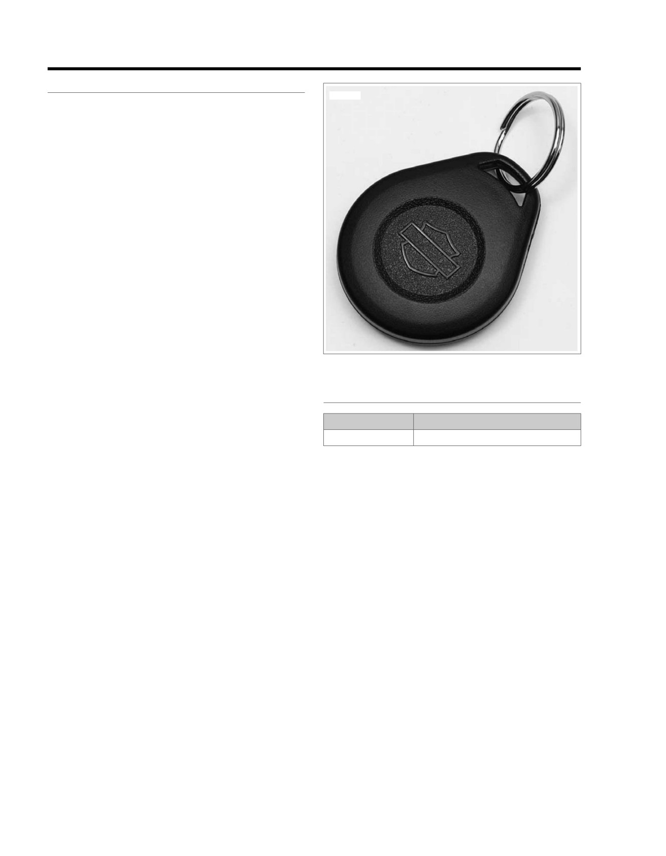
KEY FOB
5.12
DESCRIPTION AND OPERATION
ed02829
See Figure 5-36. The fob's reception range for the signal
depends on a specific receiver pattern. The typical range will
be an arm's length.
NOTES
•
Environmental and geographic conditions impact signal
range.
•
Always have the fob present whenever the vehicle is
operated.
•
Do not place fob in metal enclosure. Do not place it closer
than 3.0 in. (80.0 mm) to cellular phones, the handsfree
antenna, PDAs, displays and other electronic devices
while operating the vehicle. That may prevent the fob from
disarming the security system.
•
Replace the fob battery every year.
Figure 5-36. Hands-Free Fob
FOB ASSIGNMENT
PART NUMBER
TOOL NAME
HD-48650
DIGITAL TECHNICIAN II
Use DIGITAL TECHNICIAN II (Part No. HD-48650) to assign
both fobs to the H-DSSS. Follow the menu prompts in the
DIGITAL TECHNICIAN II (Part No. HD-48650) display and
scan the fob serial number with the bar code reader, or key-in
the number from the keyboard.
NOTE
Each fob has a unique serial number. Attach fob label to a
blank NOTES page in the owner's manual for reference.
5-56 2013 Softail Diagnostics: Accessories, Horn, Lighting and Security
HOME
SIREN
5.13
DESCRIPTION AND OPERATION
ed03462
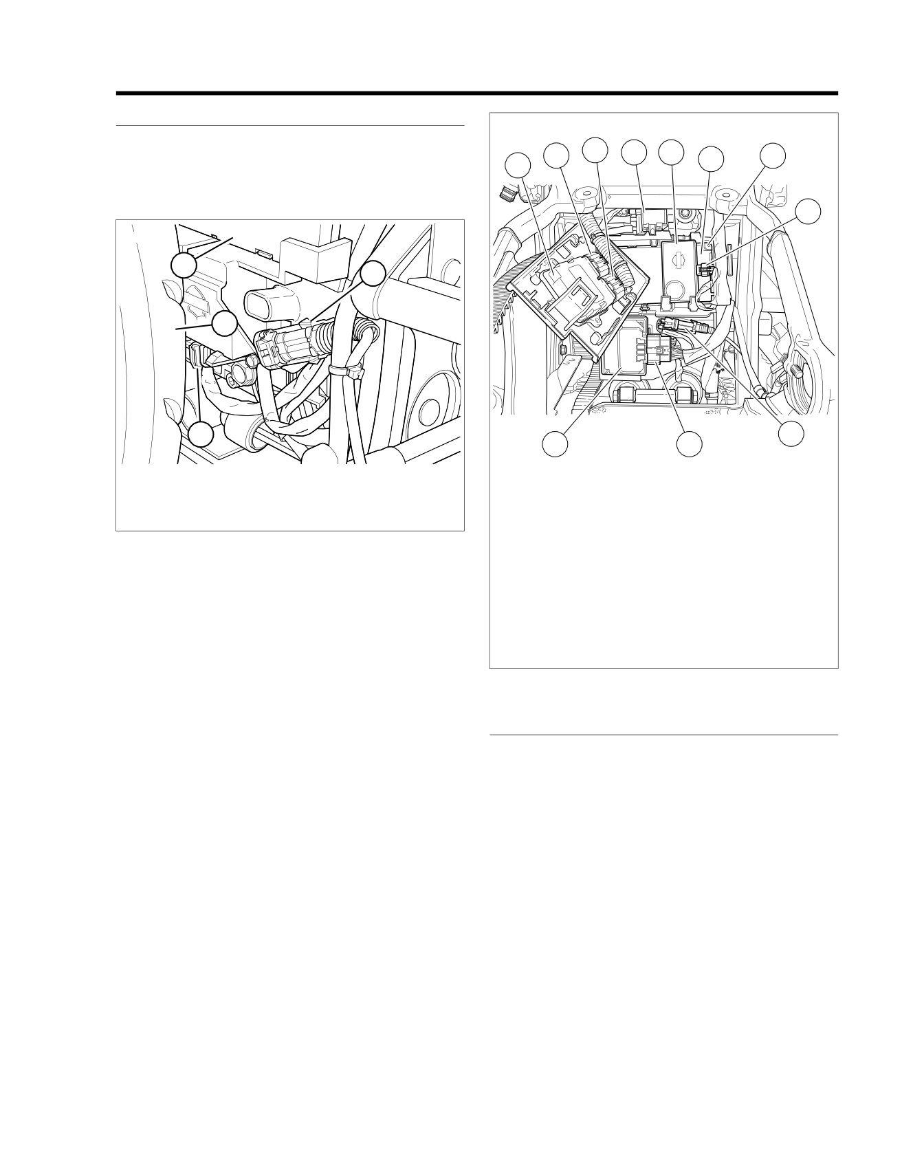
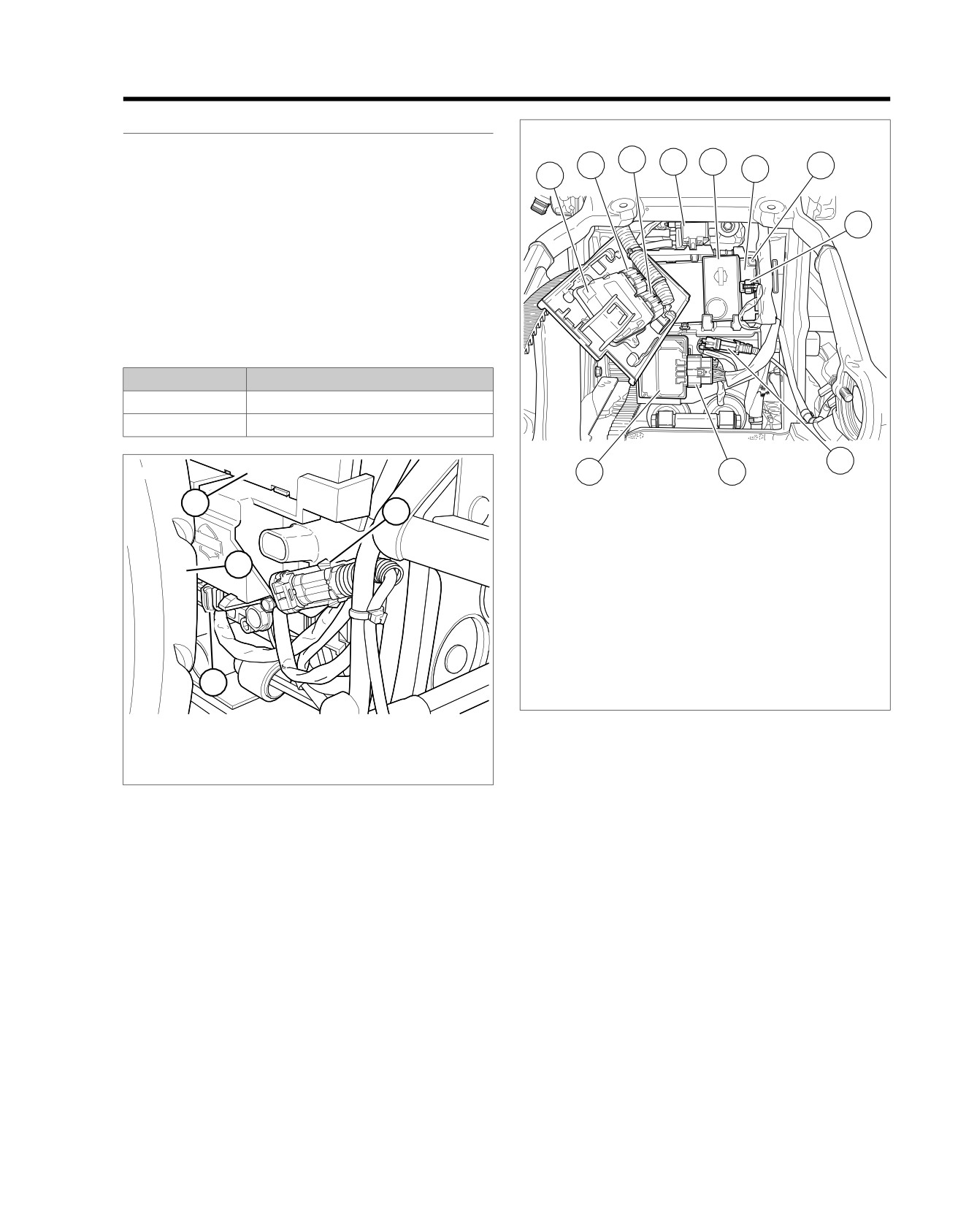
See Figure 5-37 and Figure 5-38. If equipped, the siren is
3
4
5
attached at [142] off the BCM. Through this connector it shares
2
6
7
1
the battery circuit, the ground circuit and the alarm signal circuit
with the BCM. The siren adds an audible warning to the visual
warnings that are a standard function of the security system.
8
ed03309
1
2
4
3
9
11
10
1.
BCM
1. ECM
2.
Rear WSS [168]
2. ECM [78-2]
3.
Security siren [142]
3. ECM [78-1]
4.
Rear tire
4. Purge solenoid [95] (back side of purge
Figure 5-37. BCM: Except FXSB
solenoid)
5. Security siren
6. BCM
7. BCM [242] (back side of BCM)
8. Security siren [142]
9. Rear WSS [168]
10. ABS [166]
11. ABS ECU
Figure 5-38. Electrical Panel: FXSB
SIREN CHIRP MODE CONFIRMATION
Chirpless Mode
In the chirpless mode, the siren does not chirp on arming or
disarming.
NOTE
Even when armed in the chirpless mode, the siren still chirps
warnings on movement and will activate the alarm through the
normal cycles.
Chirp Mode
On arming in the chirp mode, the siren responds with two
chirps. When disarming, the siren responds with a single chirp.
Switching Modes
Cycling quickly through three armings and disarmings will
switch chirp mode.
1. With the fob present, the IGN ON and the system dis-
armed, turn the IGN OFF.
2013 Softail Diagnostics: Accessories, Horn, Lighting and Security 5-57
HOME
2. When the security lamp turns off, immediately turn the
sequence and will have to be started over from the
IGN ON. If the turn signals flash twice before the IGN is
beginning.
turned ON, the system will drop out of the switching mode
5. Wait until the security lamp goes out, then immediately
sequence and will have to be started over from the
turn the IGN OFF.
beginning.
6. When the security lamp turns off, immediately turn the
3. Wait until the security lamp goes out, then immediately
IGN ON. If the turn signals flash twice before the IGN is
turn the IGN OFF.
turned ON, the system will drop out of the switching mode
4. When the security lamp turns off, immediately turn the
sequence and will have to be started over from the
IGN ON. If the turn signals flash twice before the IGN is
beginning.
turned ON, the system will drop out of the switching mode
5-58 2013 Softail Diagnostics: Accessories, Horn, Lighting and Security
HOME
SERVICE AND EMERGENCY FUNCTIONS AND
CONFIGURATIONS
5.14
GENERAL
INITIAL PIN ENTRY
Setting up a vehicle's security requires a BCM that is security
PART NUMBER
TOOL NAME
equipped.
HD-48650
DIGITAL TECHNICIAN II
ACTUATION
Actuation consists of assigning two fobs to the system and
The initial PIN entry should be performed using DIGITAL
entering an initial PIN. The PIN can be changed by the rider
TECHNICIAN II (Part No. HD-48650) in conjunction with fob
at any time.
assignment.
1. Configure vehicles by assigning both fobs to the vehicle.
CHANGING THE PIN
2. Configure vehicles by entering a PIN picked by the owner.
To change a PIN, refer to Table 5-54.
The personal code allows the owner to operate the system
If a PIN was previously entered, the odometer will display the
if the fob is lost or inoperable. Record the PIN in the
equivalent digit. To increment the digits, press the left turn
owner's manual wallet card. Instruct the customer to
signal switch. The first press selects the same value and then
always carry this card when riding the motorcycle.
each additional press of the left turn signal switch will increment
Once the system has been activated, it will always arm within
the digit by one.
five seconds of turning the ignition switch to OFF or ACC and
Examples:
no vehicle motion.
•
To advance from 5 to 6, press and release the left turn
SELECTING A PIN
switch twice.
The PIN consists of five digits. Each digit can be any number
•
To advance from 8 to 2, press and release the left turn
from 1-9. There can be no zeros (0) in the PIN. The PIN must
switch four times.
be used to disarm the security system in case the fob becomes
unavailable.
Table 5-54. Changing the PIN
STEP
ACTION
WAIT FOR CONFIRMATION
NOTES
NO.
1
Select a 5-digit (1 thru 9) PIN and
record on the wallet card from Owner's
Manual.
2
With an assigned fob present, turn the
OFF/RUN switch to OFF.
3
Turn the ignition switch to IGN.
4
Cycle the OFF/RUN switch twice: RUN
- OFF - RUN - OFF - RUN.
5
Press left turn signal switch 2 times.
ENTER PIN will scroll through the
odometer window.
6
Press right turn signal switch 1 time
Turn signals will flash 3 times. Current
and release.
PIN will appear in odometer. The first
digit will be flashing.
7
Enter first digit of new PIN by pressing
and releasing the left turn signal switch
until the selected digit appears.
8
Press right turn signal switch 1 time
The new digit will replace the current
and release.
in odometer window.
9
Enter second digit of selected PIN by
pressing and releasing the left turn
signal switch until the selected digit is
present.
10
Press right turn signal switch 1 time
The new digit will replace the current
and release.
in odometer window.
2013 Softail Diagnostics: Accessories, Horn, Lighting and Security 5-59
HOME
Table 5-54. Changing the PIN
STEP
ACTION
WAIT FOR CONFIRMATION
NOTES
NO.
11
Enter third digit of the selected PIN by
pressing and releasing the left turn
signal switch until the selected digit is
present.
12
Press right turn switch 1 time and
The new digit will replace the current
release.
in odometer window.
13
Enter fourth digit of new PIN by
pressing and releasing the left turn
signal switch until the selected digit is
present.
14
Press right turn switch 1 time and
The new digit will replace the current
release.
in odometer window.
15
Enter fifth digit of the new PIN by
pressing and releasing the left turn
signal switch until the selected digit is
present.
16
Press right turn switch 1 time and
The new digit will replace the current
release.
in odometer window.
17
Turn the OFF/RUN switch OFF, then
Pushing the OFF/RUN switch to OFF
turn the ignition switch to OFF.
stores the new PIN in the module.
TRANSPORT MODE
SERVICE MODE
When transporting the motorcycle, place the system in the
PART NUMBER
TOOL NAME
transport mode. Otherwise, the alarm activated by motion
detection can discharge the battery.
HD-48650
DIGITAL TECHNICIAN II
In the transport mode, the security system is armed without
With a fob present, the security system can be configured for
enabling the motion detector for one ignition cycle. This allows
service by disabling the security system with DIGITAL TECH-
the vehicle to be picked up and moved in an armed state,
NICIAN II (Part No. HD-48650).
however, any attempt to start the engine when the fob is not
within range will trigger the alarm.
Once disabled, the vehicle can be operated without an assigned
fob present. To maintain the Service Mode, the assigned fobs
To Enter Transport Mode
must be kept out of range. If the fob appears in range, the
1. With an assigned fob within range, turn the ignition switch
Service Mode will be exited.
to IGN.
FOUR-WAY FLASHING
2. Before the security system lamp goes out, turn the ignition
switch to OFF.
To Arm the Security System with the Hazard
Warning Flashers ON
3. Within three seconds, simultaneously press both the left
and the right turn signal switches.
If it is necessary to leave a vehicle parked along side the road,
the hazard warning four-way flashers can be turned ON with
4. After the turn signals flash once, the system enters the
the smart security system armed.
transport mode. With the fob removed, the motorcycle can
be moved without setting off the alarm.
1. Turn IGN ON or ACC.
To Exit Transport Mode
2. Press the hazard warning switch. The four-way flashers
will continue for two hours.
With the fob present, turn the ignition switch to IGN to disarm
the system.
3. Turn IGN OFF to arm the smart security system.
To Disarm the Security System and Turn
the Hazard Warning Flashers OFF
1. With a fob present, turn IGN to ON or ACC.
2. Press the hazard warning switch.
5-60 2013 Softail Diagnostics: Accessories, Horn, Lighting and Security
HOME
DTC B2172,
B2173
5.15
DESCRIPTION AND OPERATION
ed03462
NOTE
3
4
5
2
7
This section applies only to those vehicles equipped with the
6
1
optional security system.
See Figure 5-39 and Figure 5-40. An alarm cycle is activated
when the BCM is connected, the siren has been armed by the
8
BCM and a security event occurs. See 5.11 SECURITY
SYSTEM. Under normal armed operation, the siren input (ter-
minal 2) is driven low by the BCM to trigger the audible alarm.
When the siren input is driven high by the BCM the audible
alarm stops.
Table 5-55. Code Description
DTC
DESCRIPTION
B2172
Security siren output shorted high
B2173
Security siren output shorted low
9
ed03309
11
10
1
2
1.
ECM
2.
ECM [78-2]
3.
ECM [78-1]
4
4.
Purge solenoid [95] (back side of purge
solenoid)
5.
Security siren
6.
BCM
7.
BCM [242] (back side of BCM)
8.
Security siren [142]
9.
Rear WSS [168]
3
10. ABS [166]
11. ABS ECU
1.
BCM
Figure 5-40. Electrical Panel: FXSB
2.
Rear WSS [168]
3.
Security siren [142]
Diagnostic Tips
4.
Rear tire
•
If the siren is armed and the internal siren battery is dead,
Figure 5-39. BCM: Except FXSB
shorted, disconnected or has been charging for a period
longer than 24 hours, the siren will respond with three
chirps on arming instead of two.
•
The internal siren battery may not charge if the vehicle's
battery is less than 12.5V.
•
If the siren does not chirp two or three times on a valid
arming command from the BCM, the chirp function has
been disabled, the siren is either not connected, not
working or the siren wiring was opened or shorted while
the siren was disarmed.
•
If the siren enters the self-driven mode where it is powered
from the siren internal 9V battery, the turn-signal lamps
will not alternately flash. If the BCM activates the siren,
the turn-signal lamps will flash. If the siren has been armed
and a security event occurs, and the siren is in self-driven
mode, the siren will alarm for 20-30 seconds and then turn
2013 Softail Diagnostics: Accessories, Horn, Lighting and Security 5-61
HOME
off for 5-10 seconds. This alarm cycle will be repeated ten
event has occurred. See 5.11 SECURITY SYSTEM for a
times if the siren is in the self-driven mode.
description of alarm functions.
•
If the siren does not stop alarming after it has been armed,
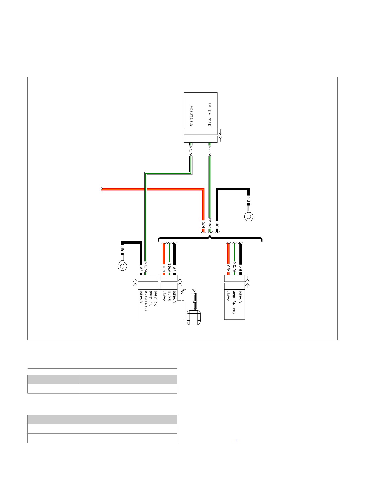
Connector Information
then either the BCM output or siren input may be shorted
For additional information about the connectors in the following
to ground, the siren vehicle battery connection is open or
diagram(s) and diagnostic procedure(s), including the color of
the siren vehicle ground connection is open or a security
the harness test kit terminal probes, see B.1 CONNECTORS.
em00878
BCM
A3
H2
[242A]
A3
H2
[242B]
Battery
Fuse
GND 2
(If
Equipped)
GND 3
[266B]
D C B A
1
2
3
[142B]
1
2
3
[142B]
[266A]
D C B A
1
2
3
[142A]
1
2
3
[142A]
Anti-theft
Security Siren
Tracking Module
(Optional)
Figure 5-41. Smart Siren Circuit
DTC B2172
1. Siren Circuit Short to Voltage Test
1. Disconnect siren [142] (if equipped).
PART NUMBER
TOOL NAME
2. Using HARNESS CONNECTOR TEST KIT (Part No. HD-
HD-41404
HARNESS CONNECTOR TEST KIT
41404), test voltage between [142] terminal 2 and ground.
NOTE
Table 5-56. DTC B2172 Diagnostic Faults
With fully charged battery normal circuit voltage is 9.0-10.5V.
POSSIBLE CAUSES
3. Is battery voltage present?
Short to voltage in alarm signal
a. Yes. Repair short to voltage in (W/GN) wire.
Siren malfunction
b. No. Go to Test 2.
5-62 2013 Softail Diagnostics: Accessories, Horn, Lighting and Security
HOME
2. DTC Test
1. Siren Signal Short to Ground Test
1. Clear DTCs.
1. Disconnect security siren [142] (if equipped).
2. Turn IGN OFF. Verify security activates.
2. Turn IGN OFF.
3. Check DTCs.
3. Connect BREAKOUT BOX (Part No. HD-50390-1) and
BCM CABLE (Part No. HD-50390-2) to wire harness
4. Did DTC reset?
[242B], leaving
[242A] disconnected. See
1.2 DIA-
a. Yes. Replace BCM.
GNOSTIC TOOLS.
b. No. Replace siren.
4. Verify BCM OVERLAY (Part No. HD-50390-2-P) is in
position on BOB.
DTC B2173
5. Using HARNESS CONNECTOR TEST KIT (Part No. HD-
41404), test continuity between BOB terminal H2 and
PART NUMBER
TOOL NAME
ground.
HD-41404
HARNESS CONNECTOR TEST KIT
6. Is continuity present?
HD-50390-1
BREAKOUT BOX
a. Yes. Go to Test 2.
HD-50390-2
BCM CABLE
b. No. Repair open in (W/GN) wire between [142B] and
HD-50390-2-P
BCM OVERLAY
[242B].
2. DTC Test
Table 5-57. DTC B2173 Diagnostic Faults
1. Connect [242].
POSSIBLE CAUSES
2. Clear DTCs.
Short to ground in alarm signal
3. Turn IGN ON.
Open ground circuit
4. Check DTCs.
Open alarm signal
Siren malfunction
5. Did DTC reset?
a. Yes. Replace BCM.
b. No. Replace security siren.
2013 Softail Diagnostics: Accessories, Horn, Lighting and Security 5-63
HOME
FAILS TO DISARM: DTC B2176, B2177, B2178
5.16
If the security system does not respond, responds with limited
DESCRIPTION AND OPERATION
range or will not consistently disarm with fob within normal
DTC B2176, B2177 or B2178 will set when a fault occurs to
range, follow the fails to disarm diagnostic procedure.
the security antenna circuit used to transmit to the fob. Refer
to Table 5-58.
ed03300
1
2
3
4
5
12
11
6
10
7
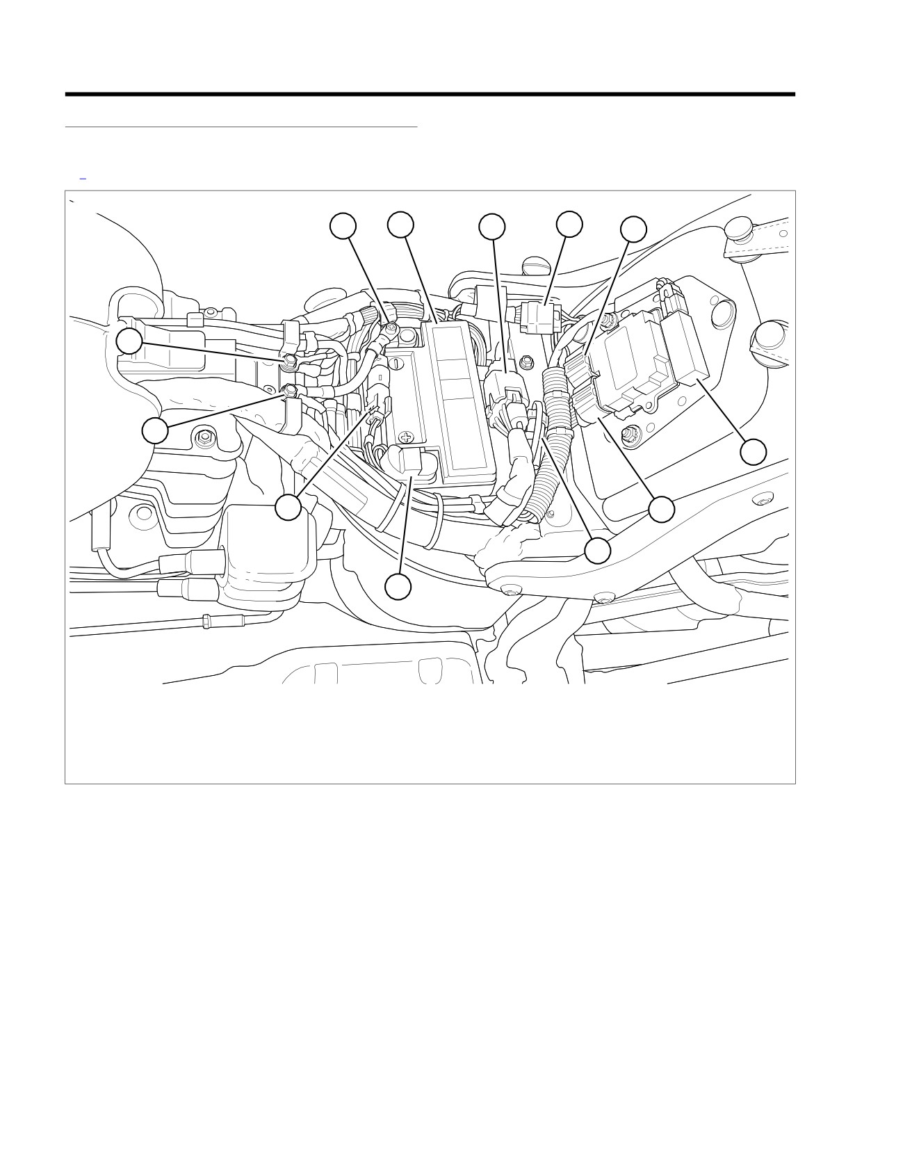
8
9
1. Battery negative
7. ECM [78B-2]
2. Battery
8. DLC [91]
3. Fuse block [64]
9. Battery positive
4. Tail lamp harness to main harness [7]
10.
Rear HO2 sensor [137]
5. ECM [78B-1]
11. Ground [GND1]
6. Security antenna [209]
12. Ground [GND2]
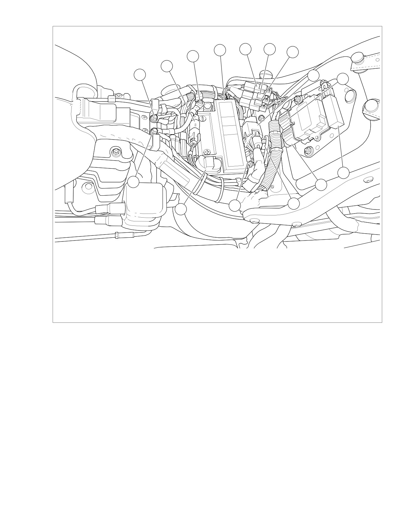
Figure 5-42. Under Seat: Except FXS/B and FLS
5-64 2013 Softail Diagnostics: Accessories, Horn, Lighting and Security
HOME
ed03468
2
3
4
5
1
15
14
6
7
8
13
9
10
11
12
1. Battery negative
9. ECM [78B-2]
2. Battery
10. DLC [91]
3. Tail lamp harness to main harness [40]
11. Fuel sender/pump jumper harness [13]
4. Left rear stop/tail/turn harness to main harness
12. Battery positive
[19]
13. Ground [GND1]
5. Right rear stop/tail/turn harness to main harness
14. Ground [GND2]
[18]
15. Rear HO2 sensor [137]
6. Fuse block [64]
7. ECM [78B-1]
8. Security antenna [209]
Figure 5-43. Under Seat: FXS and FLS
2013 Softail Diagnostics: Accessories, Horn, Lighting and Security 5-65