Harley Davidson Softail Delux FLSTN BIKE 2011-2015. Electrical Diagnostics - page 17
HOME
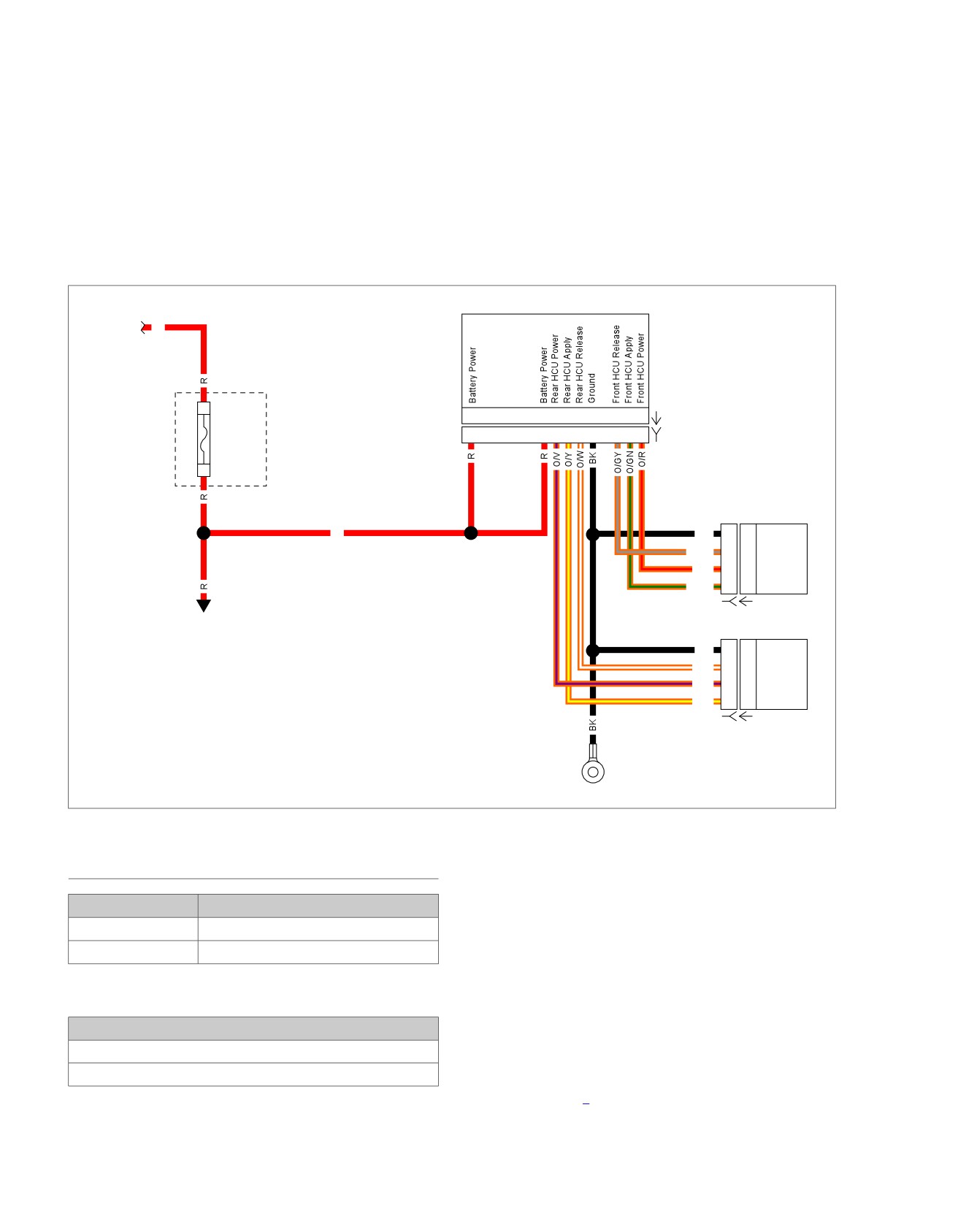
em00819
ABS Module
Battery
R
B
20
11 10 9
7
6
4
2
1
[166A]
Main
20
11 10 9
7
6
4
2
1
[166B]
40A
A
Fuse
[64B]
Block
Front HCU
R
BK
D
D
O/GY
C
C
O/R
B
B
O/GN
A
A
[254B] [254A]
Battery
Power
Rear HCU
BK
D
D
O/W
C
C
O/V
B
B
O/Y
A
A
[255B] [255A]
GND 2
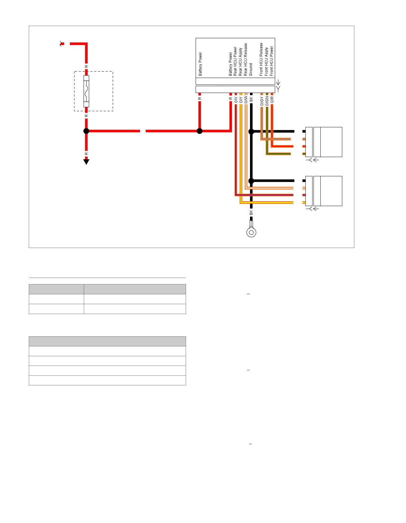
Figure 7-12. HCU Schematic
DTC C1018, C1042, C1224
5. Is continuity present?
a. Yes. Repair short to ground on (O/R) wire.
PART NUMBER
TOOL NAME
b. No. Go to Test 2.
HD-41404
HARNESS CONNECTOR TEST KIT
2. Internal Power Circuit Short to Voltage
HD-48642
ABS BREAKOUT BOX
Test
1. Turn IGN ON.
Table 7-2. DTC C1018, C1042, C1224 Diagnostic Faults
2. Test voltage between BOB terminal 1 and ground.
POSSIBLE CAUSES
3. Is battery voltage present?
Open or high resistance on the front HCU ground circuit
a. Yes. Repair short to voltage on (O/R) wire.
Open or high resistance on front HCU power circuit
b. No. Go to Test 3.
Short to ground on the front HCU power circuit
Short to power on HCU circuit
3. Ground Circuit Test
1. Front HCU Internal Power Circuit Short
1. Turn IGN OFF.
to Ground Test
2. Remove main fuse [64B].
1. Turn IGN OFF.
3. Test resistance between [254B] terminal D (BK) wire and
ground.
2. Disconnect front HCU [254].
4. Is resistance less than 0.5 Ohm?
3. Connect ABS BREAKOUT BOX (Part No. HD-48642) to
wire harness [166B], leaving ABS module [166A] discon-
a. Yes. Go to Test 4.
nected. See 1.2 DIAGNOSTIC TOOLS.
b. No. Repair open or high resistance in (BK) wire.
4. Using HARNESS CONNECTOR TEST KIT (Part No. HD-
41404), test continuity between BOB terminal 1 and
ground.
7-6 2013 Softail Diagnostics: ABS
HOME
4. Using HARNESS CONNECTOR TEST KIT (Part No. HD-
4. Power Circuit Test
41404), test continuity between BOB terminal 10 and
1. Test resistance between [254B] terminals B (O/R) wire
ground.
and BOB terminal 1.
5. Is continuity present?
2. Is resistance less than 0.5 Ohm?
a. Yes. Repair short to ground on (O/V).
a. Yes. Go to Test 5.
b. No. Go to Test 2.
b. No. Repair open or high resistance in (O/R) wire.
2. Internal Power Circuit Short to Voltage
5. Pump Motor Current Draw Test
Test
1. Connect [254].
1. Turn IGN ON.
2. Select DC Amp on DMM in range to handle 10A.
2. Test voltage between BOB terminal 10 and ground.
3. Connect red lead of DMM to battery and black lead of
3. Is battery voltage present?
DMM to BOB terminal 1.
a. Yes. Repair short to voltage on (O/V) wire.
4. Does HCU motor run drawing more than 0.5A?
b. No. Go to Test 3.
a. Yes. Go to Test 6.
b. No. Replace the HCU.
3. Ground Circuit Test
1. Remove main fuse [64B].
6. ABS ECU Test
2. Test resistance between [255B] terminal D (BK) wire and
1. Remove BOB and connect [166].
ground.
2. Clear DTCs.
3. Is resistance less than 0.5 Ohm?
3. Start vehicle. Operate in the parameters for ABS initializa-
a. Yes. Go to Test 4.
tion self-test. See 7.1 ANTI-LOCK BRAKE SYSTEM (ABS)
GENERAL INFORMATION.
b. No. Repair open or high resistance in (BK) wire.
4. Check DTCs.
4. Power Circuit Test
5. Did DTC reset?
1. Test resistance between [255B] terminal B (O/V) wire and
a. Yes. Replace ABS ECU.
BOB terminal 10.
b. No. Concern is intermittent. See 1.3 DIAGNOSTICS
2. Is resistance less than 0.5 Ohms?
AND TROUBLESHOOTING, Wiggle Test.
a. Yes. Go to Test 5.
DTC C1041, C1044, C1225
b. No. Repair open or high resistance in (O/V) wire.
5. Pump Motor Current Draw Test
PART NUMBER
TOOL NAME
1. Connect [255].
HD-41404
HARNESS CONNECTOR TEST KIT
HD-48642
ABS BREAKOUT BOX
2. Select DC Amp on DMM in range to handle 10A.
3. Connect red lead of DMM to battery and black lead of
DMM to BOB terminal 10.
Table 7-3. DTC C1041, C1044, C1225 Diagnostic Faults
4. Does HCU motor run drawing more than 0.5A?
POSSIBLE CAUSES
a. Yes. Go to Test 6.
Open or high resistance on the rear HCU ground circuit
b. No. Replace HCU.
Open or high resistance on rear HCU power circuit
Short to ground on the rear HCU power circuit
6. ABS ECU Test
Short to power on HCU circuit
1. Remove BOB and connect [166].
1. Rear HCU Internal Power Circuit Short to
2. Clear DTCs.
Ground Test
3. Start vehicle. Operate in the parameters for initialization
self-test. See 7.1 ANTI-LOCK BRAKE SYSTEM (ABS)
1. Turn IGN OFF.
GENERAL INFORMATION.
2. Disconnect rear HCU [255].
4. Check DTCs.
3. Connect ABS BREAKOUT BOX (Part No. HD-48642) to
wire harness [166B], leaving ABS module [166A] discon-
nected. See 1.2 DIAGNOSTIC TOOLS.
2013 Softail Diagnostics: ABS 7-7
HOME
5. Did DTC reset?
b.
No. Concern is intermittent. See 1.3 DIAGNOSTICS
AND TROUBLESHOOTING, Wiggle Test.
a. Yes. Replace ABS ECU.
7-8 2013 Softail Diagnostics: ABS
HOME
DTC C1021,
C1023
7.3
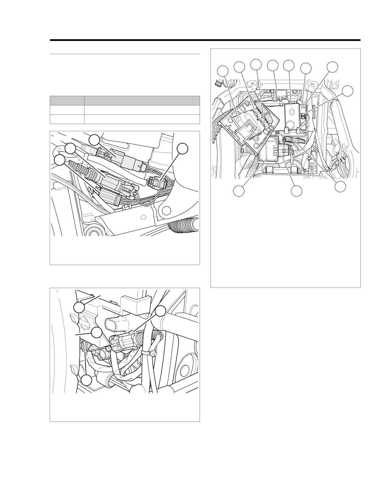
DESCRIPTION AND OPERATION
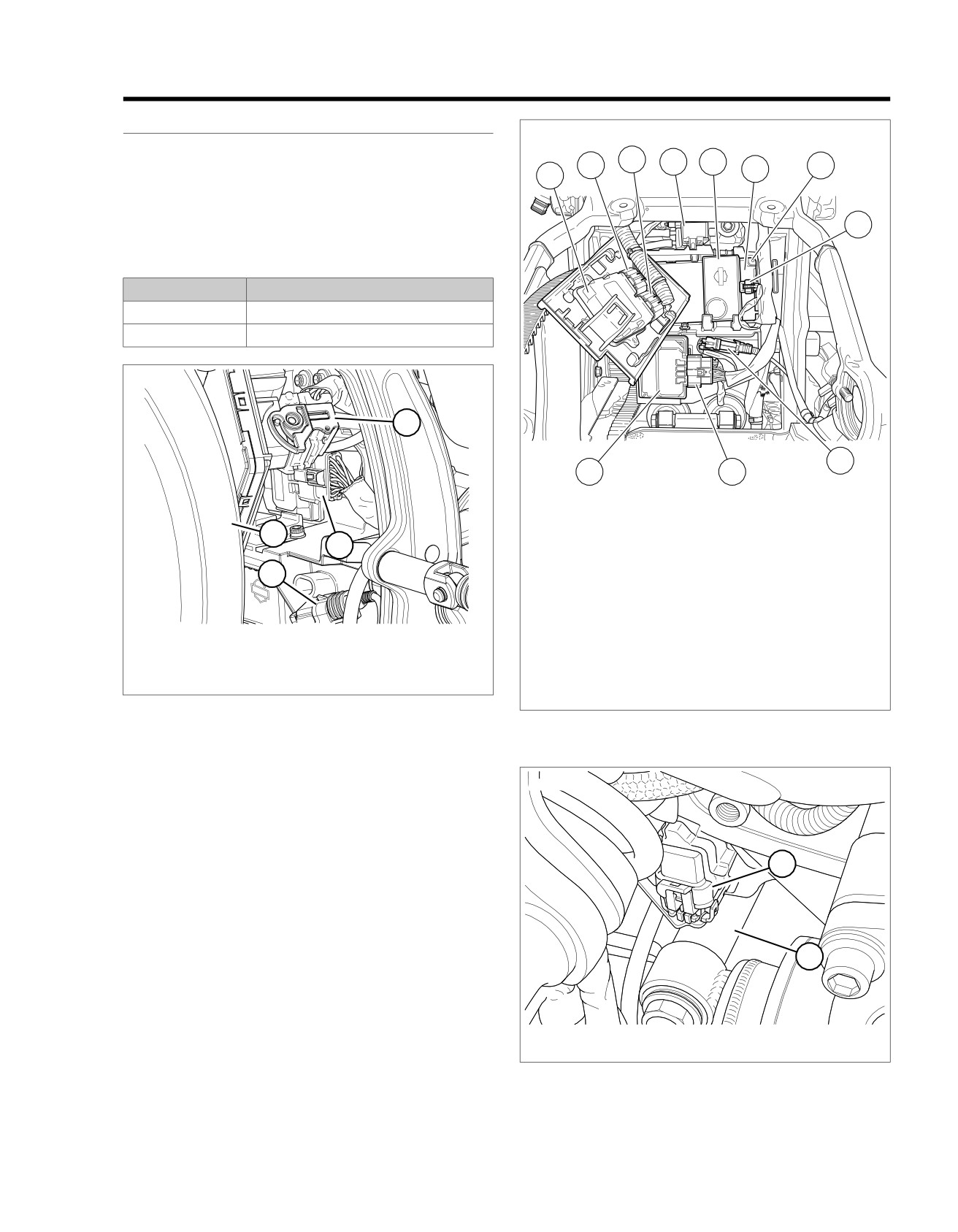
ed03462
The active WSS is supplied system voltage from the ABS
3
4
5
module. The sensor then returns a 7 mA or 14 mA signal back
2
6
7
1
to the ABS module.
Table 7-4. Code Description
8
DTC
DESCRIPTION
C1021
Front wheel speed sensor always = 0
C1023
Rear wheel speed sensor always = 0
ed03294
3
2
4
1
9
11
10
1. ECM
2. ECM [78-2]
3. ECM [78-1]
4. Purge solenoid [95] (back side of purge
solenoid)
1. Head lamp [38]
5. Security siren
2. Front WSS [167]
6. BCM
3. Instruments [20]
7. BCM [242] (back side of BCM)
4. Left hand control [24]
8. Security siren [142]
Figure 7-13. Under Fuel Tank Left Side
9. Rear WSS [168]
10. ABS [166]
11. ABS ECU
ed03309
Figure 7-15. Electrical Panel: FXSB
1
2
Conditions for Setting the DTC
The DTC will set if the frequency of the wheel speed input goes
above 2.5kHz for 20 milliseconds.
4
DTC C1021 or C1023 can set if the following conditions exist
in the low WSS circuit:
•
The wheel speed of one wheel is greater than 5 mph (8
km/h) for 2.5 seconds while the other wheel is 0 mph (0
km/h) with no brake switch input.
•
Dynamometer testing.
3
•
WSS fault or malfunction.
1. BCM
•
ABS ECU fault or malfunction.
2. Rear WSS [168]
•
Incorrect or worn bearing assembly.
3. Security siren [142]
4. Rear tire
Action Taken When the DTC Sets
Figure 7-14. BCM: Except FXSB
•
The ABS module disables the ABS.
•
The ABS indicator is illuminated.
2013 Softail Diagnostics: ABS 7-9
HOME
Diagnostic Tips
Connector Information
A correctly installed ABS wheel bearing will have a tan seal
For additional information about the connectors in the following
facing outward. If the red seal is showing, the bearing is
diagram(s) and diagnostic procedure(s), including the color of
installed backward. If the seal is black, it is a non-ABS bearing
the harness test kit terminal probes, see B.1 CONNECTORS.
and should be replaced with the correct bearing
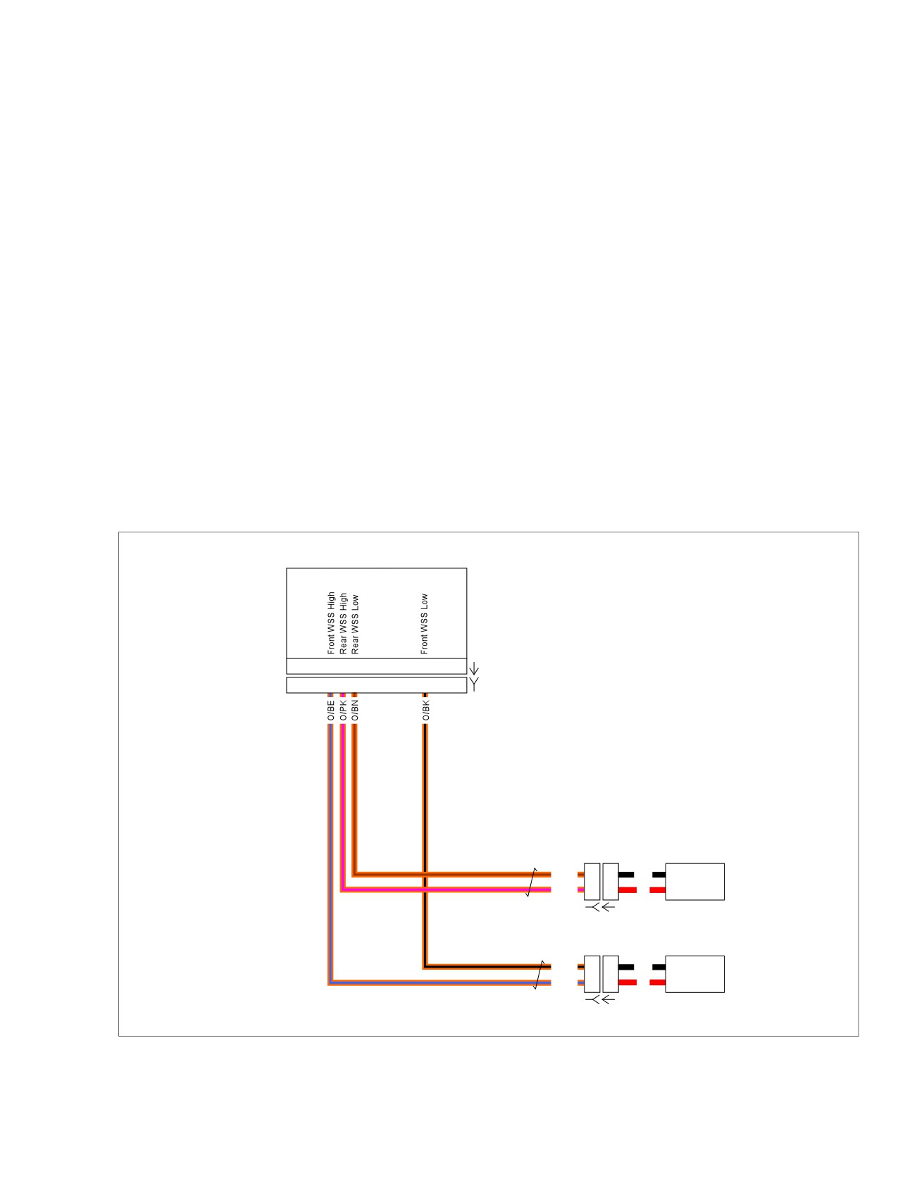
em00817
ABS Module
15 13 12
5
[166A]
15
13 12
5
[166B]
Rear WSS
O/BN
B
B
BK
O/PK
A
A
R
[168B] [168A]
Front WSS
O/BK
B
B
BK
O/BE
A
A
R
[167B] [167A]
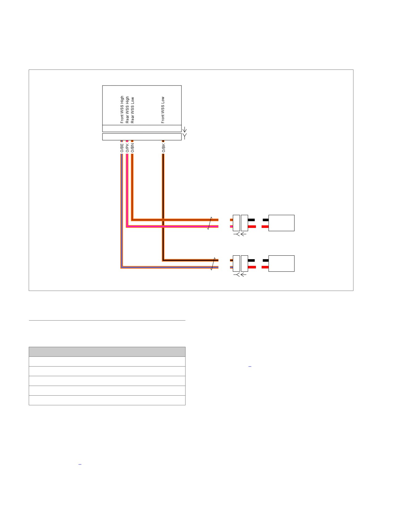
Figure 7-16. Wheel Speed Sensor Circuits
DTC C1021 (FRONT), C1023 (REAR)
2. Validation of Current DTC Test
1. Clear DTC.
Table 7-5. DTC C1021 (Front), C1023 (Rear) Diagnostic
2.
Operate vehicle above 5 mph (8 km/h) for at least 30
Faults
seconds.
POSSIBLE CAUSES
3.
Did DTC reset?
Electrical interference
a. Yes. Go to Test 3.
Poor connections
b. No. See diagnostic tips.
Intermittent open in WSS circuits
Faulty WSS
3. Worn or Damaged Components Test
Worn bearing assembly
1.
Inspect for worn, damaged or incorrect bearing assembly.
NOTES
1. Electrical Interference Test
Check ABS bearing seal color to determine if bearing is prop-
1. Inspect vehicle for accessories that may cause electrical
erly installed.
interference with the wheel speed sensors.
•
Tan seal faces outward when properly installed.
2. Electrical interference present?
•
Red seal visible indicates bearing is installed backward.
a. Yes. Remove or relocate interference.
•
Black seal visible indicates non-ABS bearings. Replace
b. No. Go to Test 2.
with correct ABS bearing.
7-10 2013 Softail Diagnostics: ABS
HOME
2. Were worn, damaged or incorrect components found?
b.
No. Replace with appropriate bearing assembly and
WSS and retest.
a. Yes. Repair as needed.
2013 Softail Diagnostics: ABS 7-11
HOME
DTC C1025,
C1032, C1206
7.4
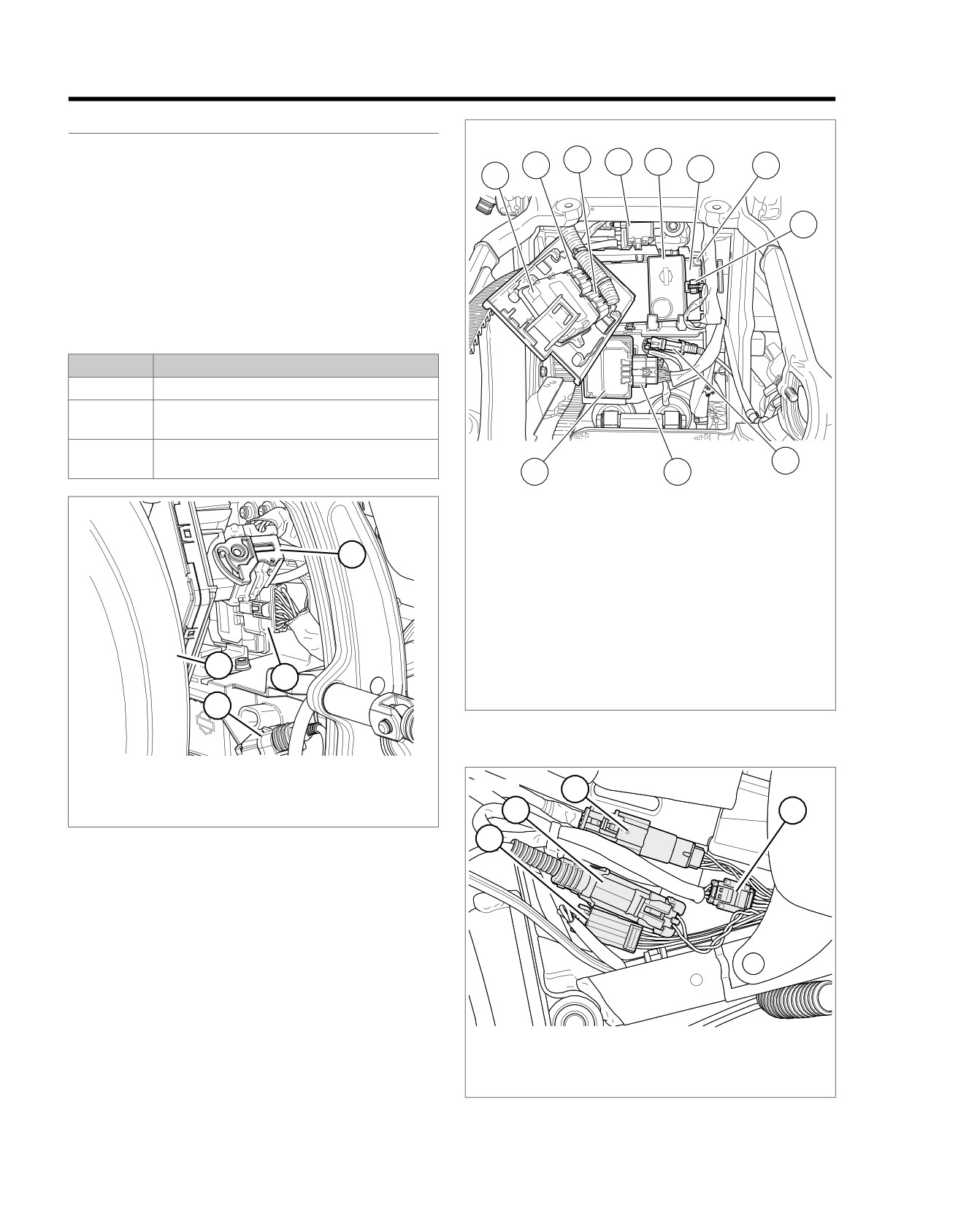
DESCRIPTION AND OPERATION
ed03462
See Figure 7-17 and Figure 7-19. The active WSS is supplied
3
4
5
system voltage from the ABS ECU. The sensor returns a 7mA
2
6
7
1
or 14mA signal back to the ABS ECU.
•
Front WSS high circuit: The ABS ECU module monitors
ignition voltage from terminal 15 of the ABS ECU through
8
terminal A of the front WSS.
•
Front WSS low circuit: The ABS ECU monitors the signal
from terminal B of the front WSS through terminal 5 of the
ABS ECU.
Table 7-6. Code Description
DTC
DESCRIPTION
C1025
Front wheel speed signal intermittent
C1032
Front wheel speed sensor circuit open or
shorted
C1206
Front wheel speed sensor frequency out of
9
range
11
10
ed03311
1.
ECM
2.
ECM [78-2]
3.
ECM [78-1]
1
4.
Purge solenoid [95] (back side of purge
solenoid)
5.
Security siren
6.
BCM
7.
BCM [242] (back side of BCM)
8.
Security siren [142]
4
9.
Rear WSS [168]
2
10. ABS [166]
11. ABS ECU
3
Figure 7-18. Electrical Panel: FXSB
1. BCM [242]
2. ABS ECU [166]
ed03294
3
3. Rear WSS [168]
2
4
4. Rear tire
Figure 7-17. ABS [166]: Except FXSB
1
1. Head lamp [38]
2. Front WSS [167]
3. Instruments [20]
4. Left hand control [24]
Figure 7-19. Under Fuel Tank Left Side
7-12 2013 Softail Diagnostics: ABS
HOME
Conditions for Setting the DTC
Action Taken When the DTC Sets
DTC C1025 can set if the following conditions exist in the front
•
ABS is disabled.
WSS low circuit:
•
The ABS indicator is illuminated.
•
One of the WSS sends a signal to the ABS ECU that the
Diagnostic Tips
wheel speed has increased or decreased at a rate that is
faster than physically possible without a brake switch input.
All the DTCs that set in this diagnostic are related to terminals
A and B of the front WSS, either internally in the ABS ECU or
•
ABS ECU fault or malfunction.
WSS, or externally in the wire or connectors. If a DTC is inter-
•
Intermittent open in the front high or low WSS circuits.
mittent, it may be a connection problem from terminal A or B
of the WSS to the ABS ECU.
•
ABS ECU fault or malfunction.
The following issues could affect the setting of these codes
•
Incorrect or worn bearing assembly.
and should be inspected before part replacement.
•
Electrical interference.
•
Mismatched or improperly sized tires.
DTC C1032 can set if one of the following conditions exist in
•
Worn suspension components.
the front high or low WSS circuit for longer than 0.02 seconds:
•
Riding over rough terrain.
•
Short to ground, short to battery, open or high resistance
in the front high or low WSS circuits.
•
External or internal wheel speed circuit intermittent open.
•
WSS fault or malfunction.
•
Electrical noise on the WSS wires.
•
ABS ECU fault or malfunction.
Connector Information
DTC C1206 can set due to the following conditions:
For additional information about the connectors in the following
•
Electrical noise on the WSS circuit.
diagram(s) and diagnostic procedure(s), including the color of
the harness test kit terminal probes, see B.1 CONNECTORS.
•
Faulty WSS and bearing assembly.
•
Faulty ABS ECU.
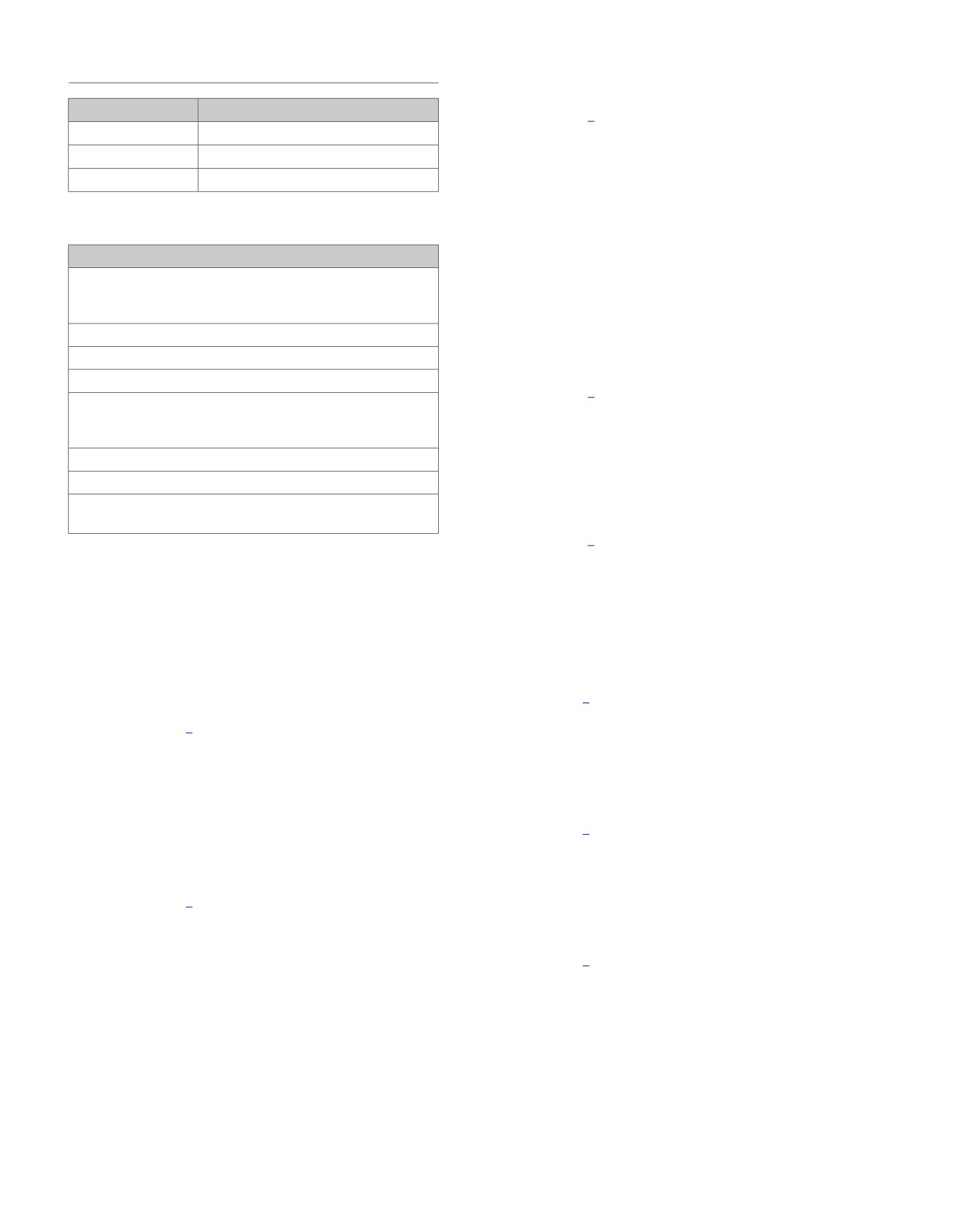
em00817
ABS Module
15 13 12
5
[166A]
15
13 12
5
[166B]
Rear WSS
O/BN
B
B
BK
O/PK
A
A
R
[168B] [168A]
Front WSS
O/BK
B
B
BK
O/BE
A
A
R
[167B] [167A]
Figure 7-20. Wheel Speed Sensor Circuits
2013 Softail Diagnostics: ABS 7-13
HOME
6. Check DTCs.
DTC C1025, C1032, C1206
7. Did DTC reset?
PART NUMBER
TOOL NAME
a. Yes. Go to Test 4.
HD-41404
HARNESS CONNECTOR TEST KIT
b. No. Replace front WSS.
HD-48642
ABS BREAKOUT BOX
HD-50341
WHEEL SPEED SENSOR TEST LEAD
4. (O/BK) Open Test
1. Turn IGN OFF.
Table 7-7. DTC C1025, C1032, C1206 Diagnostic Faults
2. Connect ABS BREAKOUT BOX (Part No. HD-48642)
between wire harness [166B] , leaving ABS module [166A]
POSSIBLE CAUSES
disconnected. See 1.2 DIAGNOSTIC TOOLS.
The wheel speed of one wheel is greater than 5 mph (8 km/h)
3. Remove sensor test lead.
for 2.5 seconds while the other wheel is 0 mph (0 km/h) with
no brake switch input
4. Using HARNESS CONNECTOR TEST KIT (Part No. HD-
41404), test continuity between BOB terminal 5 and [167B]
Dynamometer testing
terminal B (O/BK) wire.
WSS fault or malfunction
5. Is continuity present?
Worn bearing assembly
a. Yes. Go to Test 5.
One of the WSSs sends a signal to the ABS ECU that the
wheel speed has increased or decreased at a rate that is
b. No. Repair open in (O/BK) wire.
faster than physically possible without a brake switch input
5. (O/BE) Open Test
Intermittent open in the front high or low WSS circuits
1. Test continuity between BOB terminal 15 and [167B] ter-
Electrical interference
minal A (O/BE) wire.
Short to ground, short to battery, open or high resistance in
the front high or low WSS circuits
2. Is continuity present?
a. Yes. Go to Test 6.
1. Electrical Interference Test
b. No. Repair open in (O/BE) wire.
1. Inspect vehicle for accessories that may cause electrical
interference with the WSS.
6. Shorted Wires Test
2. Inspect the front wheel bearing.
1. Test continuity between BOB terminals 5 and 15.
3. Is electrical interference or wheel bearing malfunction
2. Is continuity present?
present?
a. Yes. Repair short between (O/BE) and (O/BK) wires.
a. Yes. Remove or relocate interference or correct wheel
b. No. Go to Test 7.
bearing issues.
b. No. Go to Test 2.
7. (O/BK) Ground Test
1. Test continuity between BOB terminal 5 and ground.
2. Loose or Damaged Connections Test
2. Is continuity present?
1. Turn IGN OFF.
a. Yes. Repair short to ground on (O/BK) wire.
2. See Figure 7-2 and Figure 7-3. Inspect for loose or dam-
aged connections on WSS circuits.
b. No. Go to Test 8.
3. Were poor connections found?
8. (O/BE) Ground Test
a. Yes. Repair connections and circuits.
1. Test continuity between BOB terminal 15 and ground.
b. No. Go to Test 3.
2. Is continuity present?
3. Front WSS Test
a. Yes. Repair short to ground on (O/BE) wire.
1. Turn IGN OFF.
b. No. Go to Test 9.
2. Disconnect front WSS [167].
9. (O/BK) Voltage Test
3. Connect WHEEL SPEED SENSOR TEST LEAD (Part
1. Turn IGN ON.
No. HD-50341) between [167B] terminals A and B. See
1.2 DIAGNOSTIC TOOLS.
2. Test voltage between BOB terminal 5 and ground.
4. Clear DTCs.
3. Is voltage present?
a. Yes. Repair short to voltage on (O/BK) wire.
5. Cycle IGN OFF, ON, wait 10 seconds for ABS to complete
initialization test.
b. No. Replace ABS module.
7-14 2013 Softail Diagnostics: ABS
HOME
DTC C1027,
C1034, C1208
7.5
DESCRIPTION AND OPERATION
ed03462
See Figure 7-21. The active WSS is supplied system voltage
3
4
5
from the ABS ECU. The sensor returns a 7mA or 14mA signal
2
6
7
1
back to the ABS ECU.
•
Rear WSS high circuit: The ABS ECU monitors ignition
voltage from terminal 13 of the ABS ECU through terminal
8
A of the rear WSS.
•
Rear WSS low circuit: The ABS ECU monitors the fre-
quency signal from terminal B of the rear WSS through
terminal 12 of the ABS ECU.
Table 7-8. Code Description
DTC
DESCRIPTION
C1027
Rear wheel speed signal intermittent
C1034
Rear wheel speed sensor circuit open or
shorted
C1208
Rear wheel speed sensor frequency out of
9
range
11
10
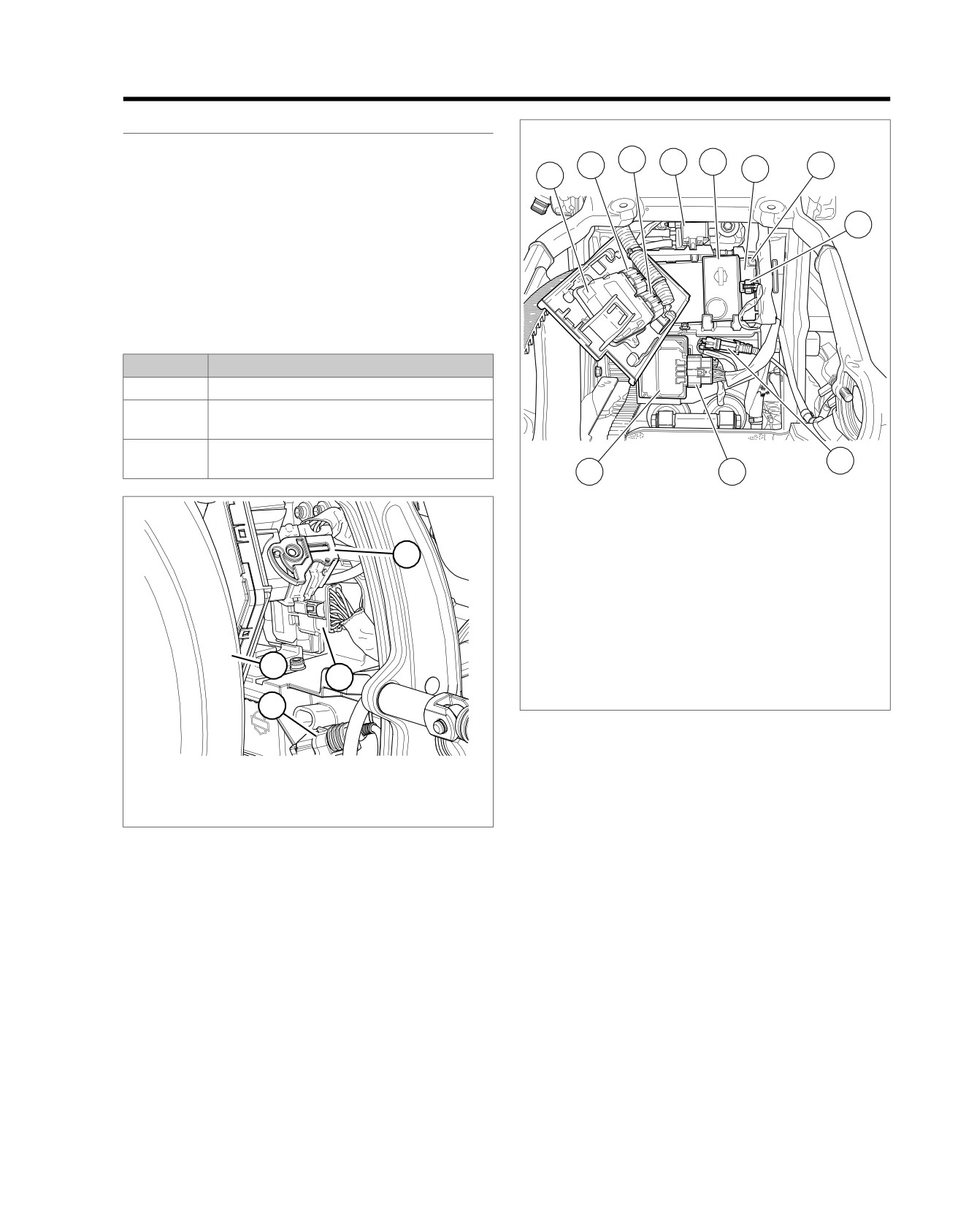
ed03311
1.
ECM
2.
ECM [78-2]
3.
ECM [78-1]
1
4.
Purge solenoid [95] (back side of purge
solenoid)
5.
Security siren
6.
BCM
7.
BCM [242] (back side of BCM)
8.
Security siren [142]
4
9.
Rear WSS [168]
2
10. ABS [166]
11. ABS ECU
3
Figure 7-22. Electrical Panel: FXSB
1.
BCM [242]
Conditions for Setting the DTC
2.
ABS ECU [166]
DTC C1027 can set if the following conditions exist in the rear
3.
Rear WSS [168]
WSS low circuit:
4.
Rear tire
•
One of the WSSs sends a signal to the ABS ECU that the
Figure 7-21. ABS [166]: Except FXSB
wheel speed has increased or decreased at a rate that is
faster than physically possible without a brake switch input.
•
ABS ECU fault or malfunction.
•
Intermittent open in the rear high or low WSS circuits.
•
Incorrect or worn bearing assembly.
•
Electrical interference.
DTC C1034 can set if one of the following conditions exist in
the rear high or low WSS circuit for longer than 0.02 seconds:
•
Short to ground, short to battery, open or high resistance
in the rear high or low WSS circuits.
•
WSS fault or malfunction.
•
ABS ECU fault or malfunction.
2013 Softail Diagnostics: ABS 7-15
HOME
DTC C1208 can set due to the following conditions:
WSS, or externally in the wire or connectors. If a DTC is inter-
mittent, it may be a connection problem from terminal A or B
•
Electrical noise on the WSS circuit.
of the WSS to the ABS ECU.
•
Faulty WSS and bearing assembly.
The following issues could affect the setting of these codes
•
Faulty ABS ECU.
and should be inspected before part replacement.
•
Mismatched or improperly sized tires.
Action Taken When the DTC Sets
•
ABS is disabled.
•
Worn suspension components.
•
Riding over rough terrain.
•
The ABS indicator is illuminated.
Connector Information
Diagnostic Tips
For additional information about the connectors in the following
All the DTCs that set in this diagnostic are related to terminals
diagram(s) and diagnostic procedure(s), including the color of
A and B of the rear WSS either internally in the ABS ECU or
the harness test kit terminal probes, see B.1 CONNECTORS.
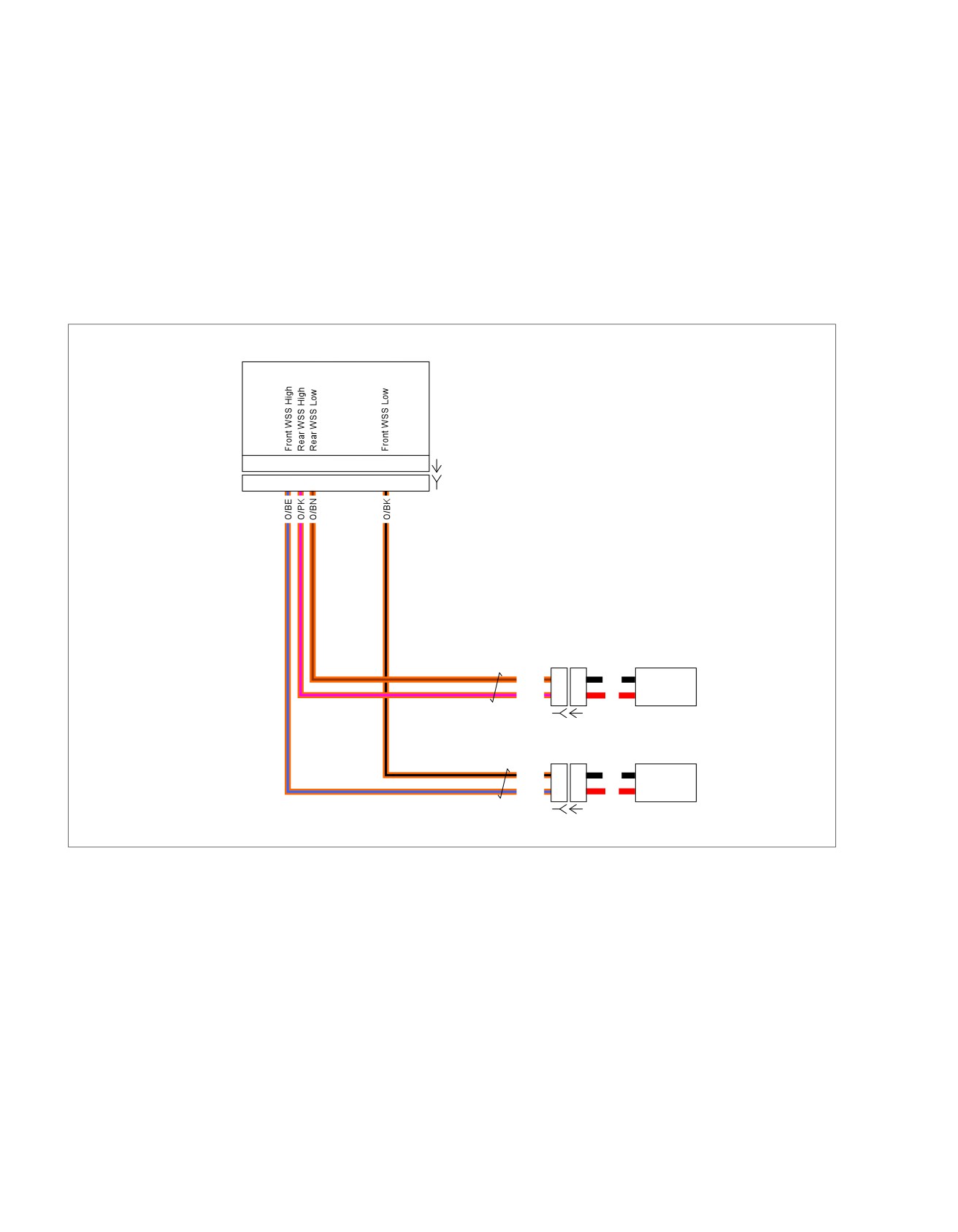
em00817
ABS Module
15 13 12
5
[166A]
15
13 12
5
[166B]
Rear WSS
O/BN
B
B
BK
O/PK
A
A
R
[168B] [168A]
Front WSS
O/BK
B
B
BK
O/BE
A
A
R
[167B] [167A]
Figure 7-23. Wheel Speed Sensor Circuits
7-16 2013 Softail Diagnostics: ABS

HOME
5. Cycle IGN OFF, ON, wait 10 seconds for ABS to complete
DTC C1027, C1034, C1208
initialization test.
PART NUMBER
TOOL NAME
6. Check DTCs.
HD-41404
HARNESS CONNECTOR TEST KIT
7. Did DTC reset?
HD-48642
ABS BREAKOUT BOX
a. Yes. Go to Test 4.
HD-50341
WHEEL SPEED SENSOR TEST LEAD
b. No. Replace front WSS.
4. (O/BN) Open Test
Table 7-9. DTC C1027, C1034, C1208 Diagnostic Faults
1. Turn IGN OFF.
POSSIBLE CAUSES
2. Connect ABS BREAKOUT BOX (Part No. HD-48642)
The wheel speed of one wheel is greater than 5 mph (8 km/h)
between wire harness [166B] , leaving ABS module [166A]
for 2.5 seconds while the other wheel is 0 mph (0 km/h) with
disconnected. See 1.2 DIAGNOSTIC TOOLS.
no brake switch input
3. Remove sensor test lead.
Dynamometer testing
WSS fault or malfunction
4. Using HARNESS CONNECTOR TEST KIT (Part No. HD-
41404), test continuity between BOB terminal 12 and
Worn bearing assembly
[168B] terminal B (O/BN) wire.
One of the wheel speed sensors sends a signal to the ABS
5. Is continuity present?
ECU that the wheel speed has increased or decreased at a
rate that is faster than physically possible without a brake
a. Yes. Go to Test 5.
switch input
b. No. Repair open in (O/BN) wire.
Intermittent open in the rear high or low WSS circuits
5. (O/PK) Open Test
Electrical interference
Short to ground, short to battery, open or high resistance in
1. Test continuity between BOB terminal 13 and [168B] ter-
the rear high or low WSS circuits
minal A (O/PK) wire.
2. Is continuity present?
1. Electrical Interference Test
a. Yes. Go to Test 6.
1. Inspect vehicle for accessories that may cause electrical
interference with the WSS.
b. No. Repair open in (O/PK) wire.
2. Inspect the rear wheel bearing.
6. Shorted Wires Test
3. Is electrical interference or wheel bearing malfunction
1. Test continuity between BOB terminals 12 and 13.
present?
2. Is continuity present?
a. Yes. Remove or relocate interference or correct wheel
a. Yes. Repair short between (O/BN) and (O/PK) wires.
bearing issues.
b. No. Go to Test 7.
b. No. Go to Test 2.
2. Loose or Damaged Connections Test
7. (O/BN) Ground Test
1. Turn IGN OFF.
1. Test continuity between BOB terminal 12 and ground.
2. See Figure 7-2 or Figure 7-3. Inspect for loose or damaged
2. Is continuity present?
connections on WSS circuits.
a. Yes. Repair short to ground on (O/BN) wire.
3. Were poor connections found?
b. No. Go to Test 8.
a. Yes. Repair connections and circuits.
8. (O/PK) Ground Test
b. No. Go to Test 3.
1. Test continuity between BOB terminal 13 and ground.
3. Rear WSS Test
2. Is continuity present?
1. Turn IGN OFF.
a. Yes. Repair short to ground on (O/PK) wire.
2. Disconnect rear WSS [168].
b. No. Go to Test 9.
3. Connect WHEEL SPEED SENSOR TEST LEAD (Part
9. (O/BN) Voltage Test
No. HD-50341) between [168B] terminals A and B. See
1.2 DIAGNOSTIC TOOLS.
1. Turn IGN ON.
4. Clear DTCs.
2. Test voltage between BOB terminal 12 and ground.
2013 Softail Diagnostics: ABS 7-17
HOME
3. Is voltage present?
b. No. Replace ABS module.
a. Yes. Repair short to voltage on (O/BN) wire.
7-18 2013 Softail Diagnostics: ABS
HOME
DTC C1052,
C1102
7.6
DESCRIPTION AND OPERATION
ed03462
See Figure 7-24 and Figure 7-26.
3
4
5
2
6
7
The ABS ECU monitors current flowing through terminal B of
1
the rear HCU power circuit. This circuit supplies the power to
the pump motor in the HCU. The ABS ECU controls the pump
by turning on and off the power circuit to the pump motor.
8
Table 7-10. Code Description
DTC
DESCRIPTION
C1052
Rear actuator circuit high
C1102
Rear acutator motor stalled
ed03311
1
9
11
10
1.
ECM
4
2.
ECM [78-2]
2
3.
ECM [78-1]
4.
Purge solenoid [95] (back side of purge
3
solenoid)
5.
Security siren
6.
BCM
1. BCM [242]
7.
BCM [242] (back side of BCM)
2. ABS ECU [166]
8.
Security siren [142]
3. Rear WSS [168]
9.
Rear WSS [168]
4. Rear tire
10. ABS [166]
11. ABS ECU
Figure 7-24. ABS [166]: Except FXSB
Figure 7-25. Electrical Panel: FXSB
ed03306
1
2
1. Rear HCU [255]
2. Rear fork
Figure 7-26. Rear HCU [255]
2013 Softail Diagnostics: ABS 7-19
HOME
Conditions for Setting the DTC
Diagnostic Tips
DTC C1052 and C1102 can set if one of the following condi-
All the DTCs that set in this diagnostic are related to terminal
tions exists in the rear HCU power circuit:
B of the rear HCU, either internally in the ABS ECU or HCU,
or externally in the wire or connectors. If a DTC is intermittent,
•
Short to ground on the rear HCU power circuit.
it may be a connection problem from terminal B of the rear
•
HCU fault or malfunction.
HCU to the ABS ECU.
•
ABS ECU fault or malfunction.
Connector Information
Action Taken When the DTC Sets
For additional information about the connectors in the following
diagram(s) and diagnostic procedure(s), including the color of
•
ABS is disabled.
the harness test kit terminal probes, see B.1 CONNECTORS.
•
The ABS indicator is illuminated.
em00819
ABS Module
Battery
R
B
20
11 10 9
7
6
4
2
1
[166A]
Main
20
11 10 9
7
6
4
2
1
[166B]
40A
A
Fuse
[64B]
Block
Front HCU
R
BK
D
D
O/GY
C
C
O/R
B
B
O/GN
A
A
[254B] [254A]
Battery
Power
Rear HCU
BK
D
D
O/W
C
C
O/V
B
B
O/Y
A
A
[255B] [255A]
GND 2
Figure 7-27. HCU Schematic
DTC C1052, C1102
1. Rear HCU Internal Power Circuit Short to
Ground Test
PART NUMBER
TOOL NAME
1. Turn IGN OFF.
HD-39617
FLUKE AC/DC CURRENT PROBE
2. Disconnect rear HCU [255].
HD-48642
ABS BREAKOUT BOX
3. Connect ABS BREAKOUT BOX (Part No. HD-48642) to
wire harness [166B], leaving ABS module [166A] discon-
Table 7-11. DTC C1052, C1102 Diagnostic Faults
nected. See 1.2 DIAGNOSTIC TOOLS.
POSSIBLE CAUSES
4. Test continuity between BOB terminal 10 and ground.
HCU fault or malfunction
5. Is continuity present?
Short to ground on the rear HCU power circuit
a. Yes. Repair short to ground on (O/V).
b. No. Go to Test 2.
7-20 2013 Softail Diagnostics: ABS
HOME
2. Pump Motor Current Draw Test
3. ABS ECU Test
1. Connect [255].
1. Remove BOB and connect [166].
2. Connect jumper wire to BOB terminal 10.
2. Clear DTCs.
3. Using FLUKE AC/DC CURRENT PROBE (Part No. HD-
3. Start vehicle. Operate in the parameters for initialization
39617) or equivalent, install clamp around jumper.
self-test. See 7.1 ANTI-LOCK BRAKE SYSTEM (ABS)
GENERAL INFORMATION.
4. Connect other end of jumper to battery positive terminal.
4. Check DTCs.
5. Does HCU motor draw more than 7A?
5. Did the DTC reset?
a. Yes. Replace HCU.
a. Yes. Replace ABS ECU.
b. No. Go to Test 3.
b. No. Concern is intermittent. See 1.3 DIAGNOSTICS
AND TROUBLESHOOTING, Wiggle Test.
2013 Softail Diagnostics: ABS 7-21
HOME
DTC C1055
7.7
DESCRIPTION AND OPERATION
ed03462
Circuit Description
3
4
5
2
6
7
The ABS module monitors the voltage level available for system
1
operation. A low voltage condition prevents the system from
operating properly. The ABS module also performs several
self-tests for internal problems which may affect proper opera-
8
tion.
Table 7-12. Code Description
DTC
DESCRIPTION
C1055
ABS ECU internal fault
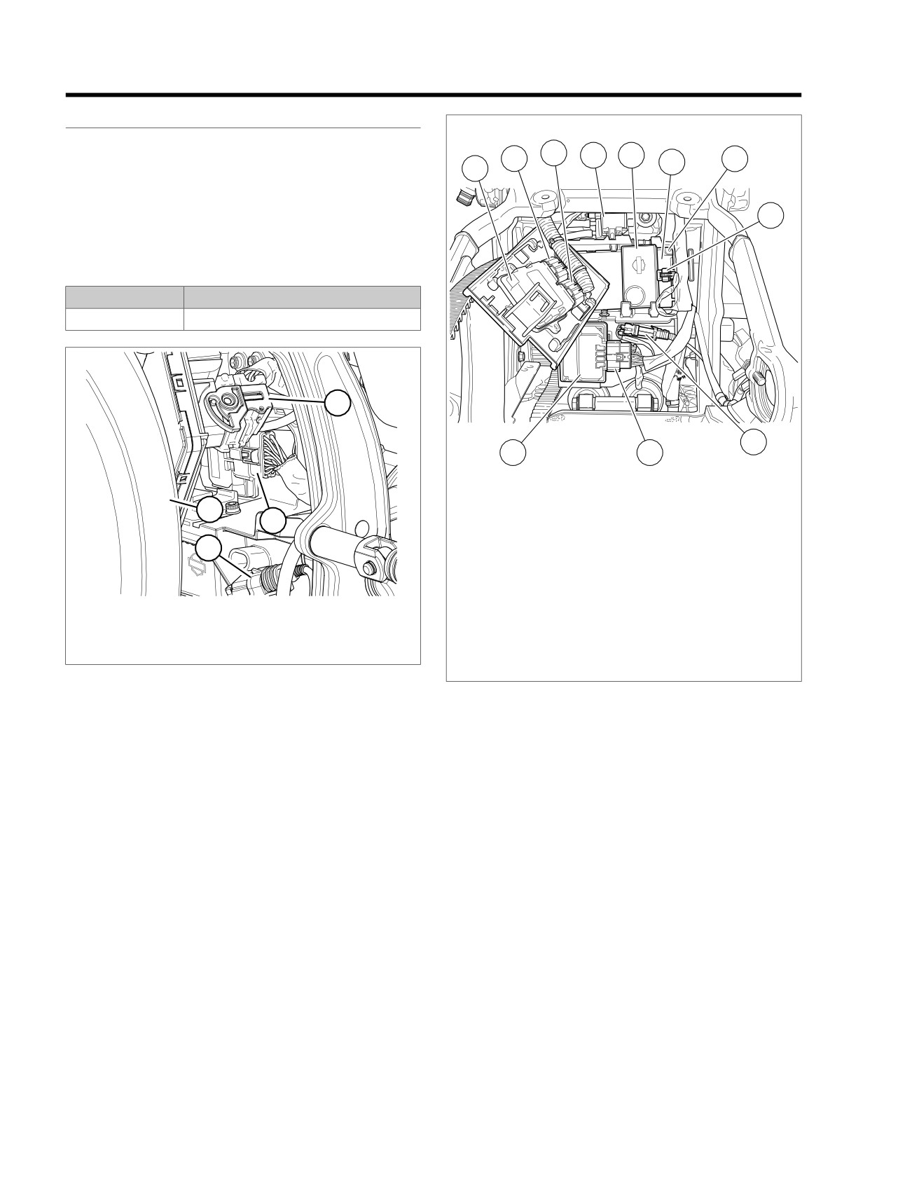
ed03311
1
9
11
10
1.
ECM
4
2.
ECM [78-2]
2
3.
ECM [78-1]
4.
Purge solenoid [95] (back side of purge
3
solenoid)
5.
Security siren
6.
BCM
1.
BCM [242]
7.
BCM [242] (back side of BCM)
2.
ABS ECU [166]
8.
Security siren [142]
3.
Rear WSS [168]
9.
Rear WSS [168]
4.
Rear tire
10. ABS [166]
11. ABS ECU
Figure 7-28. ABS [166]: Except FXSB
Figure 7-29. Electrical Panel: FXSB
Conditions for Setting the DTC
The ABS module detects an internal malfunction.
Action Taken When the DTC Sets
•
ABS is disabled.
•
The ABS indicator is illuminated.
Diagnostic Tips
If improper voltage is supplied to the ABS ECU, this code may
set. Using an improper or high voltage charger on the vehicle
may cause this code to inadvertently set when there is nothing
wrong with the ABS system.
Connector Information
For additional information about the connectors in the following
diagram(s) and diagnostic procedure(s), including the color of
the harness test kit terminal probes, see B.1 CONNECTORS.
7-22 2013 Softail Diagnostics: ABS
HOME
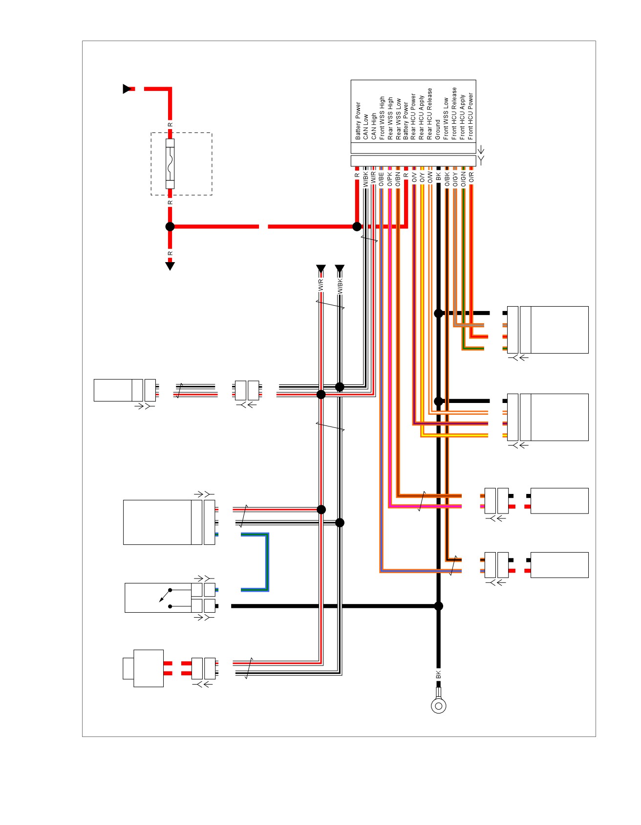
em00992
ABS Module
Battery
R
B
20 19 18 15 13 12 11 10
9
7
6
5
4
2
1
[166A]
Main
20 19 18 15 13 12 11 10
9
7
6
5
4
2
1
[166B]
40A
A
Fuse
[64B]
Block
R
CAN
Communication
Battery
Power
Front HCU
BK
D
D
Ground
O/GY
C
C
Front HCU Release
O/R
B
B
Front HCU Power
O/GN
A
A
Front HCU Apply
[254B] [254A]
Speedometer
CAN Low
8
8
W/BK
W/BK
3
3
W/BK
Rear HCU
CAN High
2
2
W/R
W/R
1
1
W/R
BK
D
D
Ground
[20B] [20A]
O/W
C
C
Rear HCU Release
[39A] [39B]
O/V
B
B
Rear HCU Power
O/Y
A
A
Rear HCU Apply
[255B] [255A]
Rear WSS
[242A] [242B]
O/BN
B
B
BK
Rear WSS Low
O/PK
A
A
R
Rear WSS High
CAN High
D2
D2
W/R
BCM
CAN Low
E2
E2
W/BK
[168B] [168A]
Brake Switch Input
F3
F3
BE/GN
Front WSS
O/BK
B
B
BK
Front WSS Low
[121A-1] [121B-1]
O/BE
A
A
R
Front WSS High
Rear
1
1
BE/GN
[167B] [167A]
Brake
Switch
1
1
BK
[121A-2] [121B-2]
Front
R
3
3
W/R
Brake
R
4
4
W/BK
Switch
[22B-1] [22A-1]
Right
Hand
Control
Module
GND 2
Figure 7-30. ABS Schematic
2013 Softail Diagnostics: ABS 7-23
HOME
5. Is voltage between 10.5-17V?
DTC C1055
a. Yes. Go to Test 3.
PART NUMBER
TOOL NAME
b. No. Go to Test 2.
HD-41404
HARNESS CONNECTOR TEST KIT
2. Battery Power Circuit Resistance Test
HD-48642
ABS BREAKOUT BOX
1. Turn IGN OFF.
2. Disconnect main fuse [64B].
Table 7-13. DTC C1055 Diagnostic Faults
3. Test resistance between BOB terminals 11 and 20, and
POSSIBLE CAUSES
[64B] socket terminal A.
Internal system malfunction
4. Is resistance greater than 1 Ohm?
A faulty system voltage supply to the module
a. Yes. Repair circuit.
A faulty system ground
b. No. Inspect battery and charging system. See
1. Battery Circuit Voltage Test
3.6 CHARGING SYSTEM.
1. Turn IGN OFF.
3. Ground Circuit Resistance Test
2. Connect ABS BREAKOUT BOX (Part No. HD-48642)
1. Test resistance between BOB terminal 6 and ground.
between wire harness [166B] and ABS module [166A].
See 1.2 DIAGNOSTIC TOOLS.
2. Is high resistance or open present?
a. Yes. Repair high resistance or open condition on
3. Turn IGN ON.
ground circuit.
4. Using HARNESS CONNECTOR TEST KIT (Part No. HD-
b. No. Replace ABS ECU module.
41404), test voltage between BOB terminals 20 and 11
and ground.
7-24 2013 Softail Diagnostics: ABS
HOME
DTC C1094
7.8
DESCRIPTION AND OPERATION
Action Taken When the DTC Sets
The ABS module monitors the brake switch inputs. When the
No action is taken when this code is set. The ABS indicator
front brake is applied, the ABS module receives a CAN signal
does not illuminate and the ABS is still active.
from the RHCM.
Diagnostic Tips
When the rear brake is applied, the BCM receives input from
The following conditions are possible causes for this fault:
the rear brake switch and sends a CAN signal to the ABS
module. The ABS uses these brake signals to enhance the
•
Front brake switch stuck closed or applied during acceler-
ABS performance and operation.
ation.
•
Rear brake switch stuck closed or applied during acceler-
Table 7-14. Code Description
ation.
DTC
DESCRIPTION
•
Brake switches may be applied when unintended.
C1094
Brake switch always on
Connector Information
Conditions for Setting the DTC
For additional information about the connectors in the following
diagram(s) and diagnostic procedure(s), including the color of
The DTC will set if all of the following conditions exist for 2
the harness test kit terminal probes, see B.1 CONNECTORS.
seconds:
•
The ABS ECU sees a front or rear brake input.
•
The vehicle speed exceeds 25 mph (40 km/h).
•
The vehicle acceleration exceeds 5 mph (8 km/h) per
second.
2013 Softail Diagnostics: ABS 7-25