Harley Davidson 1986-2003 XL/XLH Sportster. Service Manual - page 20
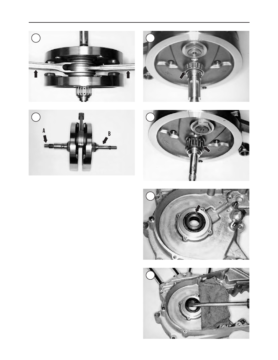
4. Inspect the sprocket shaft (A, Figure 136) and pinion
shaft (B) for severe wear or damage. If damaged, refer re-
placement to a dealership.
NOTE
If still in place, do not lose the shim (8,
Figure
128
) when performing Step 5.
5. Inspect the sprocket shaft bearing (Figure 137) for se-
vere wear or damage. If damaged, replace the bearing and
races as described in the
Sprocket Shaft Main Bearing As-
sembly Replacement
section.
6. Inspect the pinion shaft needle bearing (Figure 138) for
severe wear or damage. If the bearing is worn or damaged,
refer replacement to a dealership.
7. Support the crankshaft on a truing stand or in a lathe and
check runout at the shaft with a dial indicator and compare
it to the runout limit in Table 1. If not within specification,
refer service to a dealership.
8. Remove the left crankcase oil seal as follows:
a. On 1991-2003 models, remove the spacer (Figure
139).
b. Pry the oil seal out of the crankcase with a wide-blade
screwdriver (Figure 140). Pad the screwdrive to
avoid damaging the case.
9. Remove the left sprocket bearing (Figure 141). If dam-
aged, replace the bearing and races as described in the
Sprocket Shaft Main Bearing Assembly Replacement
sec-
tion.
238
CHAPTER FIVE
135
136
137
138
139
140