Harley Davidson 1986-2003 XL/XLH Sportster. Service Manual - page 19
and a scavenger pump, which returns oil to the oil tank from
the engine.
Removal/Installation
The gearcase cover is shown removed in this procedure
for clarity.
1. Place a drip pan underneath the engine.
2. Drain the engine oil tank (Chapter Three).
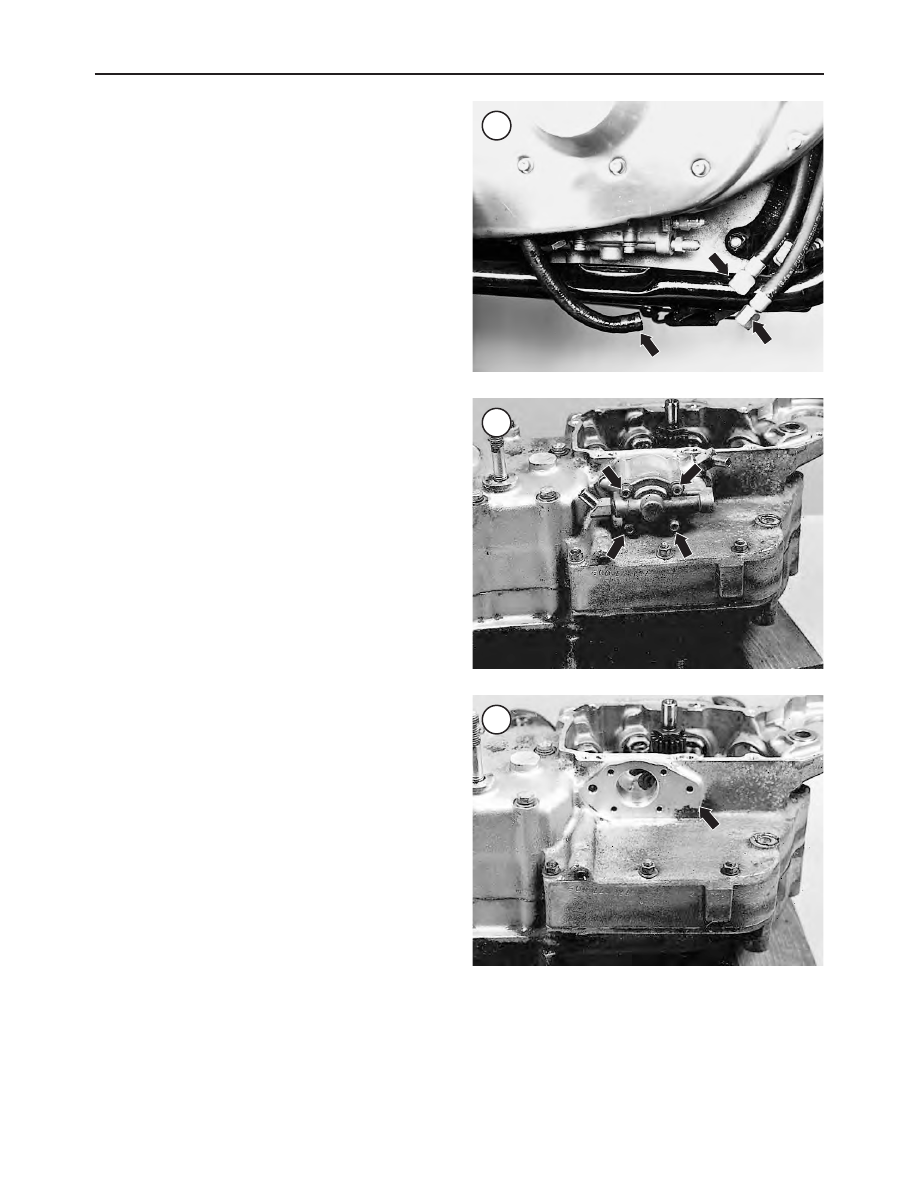
3. Disconnect the oil lines from the pump (Figure 72).
Plug the lines to prevent leaks and contamination.
4. Unscrew the bolts (Figure 73) that attach the pump to
the bottom of the crankcase and remove the pump.
5. Install by reversing these steps, noting the following:
a. Clean the crankcase oil pump machined surface (Fig-
ure 74) of all gasket residue.
b. Install a new oil pump gasket.
c. Install the bolts (Figure 73) and tighten them to
90-110 in.-lb. (10-12 N•m).
6. After installing the oil pump, refill the engine oil and
prime the pump as described in
Periodic Lubricaton
in
Chapter Three.
Disassembly
Refer to Figure 75.
1. Remove the oil pump bolts.
2. Remove the cover (Figure 76) from the pump body and
remove the O-ring (Figure 77) from the groove in the
cover.
3. Remove the outer (Figure 78) and inner (Figure 79)
feed gerotor set from the shaft. Pull the pin (Figure 80) out
of the shaft.
4. Remove the outer plate (Figure 81), spring washer (Fig-
ure 82) and the inner plate (Figure 83).
5. Remove the outer scanvenger gerotor (Figure 84).
6. Remove the circlip (Figure 85) from the gear shaft.
7. Remove the scavenger inner gerotor (Figure 86).
8. Remove the pin (Figure 87) from the shaft and remove
the gearshaft (Figure 88) from the pump body.
Cleaning/Inspection
Refer to Figure 75. Replace components not within spec-
ification as noted in Table 1.
1. Clean all of the parts with solvent and blow dry with
compressed air. Blow out all of the ports and passages to
ensure no sludge or solvent remains.
2. Replace deformed or damaged O-rings .
3. If the outer plate seal (Figure 89) is worn or damaged,
carefully pry it out of the outer plate. Tap a new seal in place.
4. Inspect the spring washer (Figure 90) for damage and
replace it if any of the fingers are broken.
5. Check the gerotor sets (Figure 91) for scoring and dam-
age. Assemble the inner and outer rotors of each set. See
Figure 92 and Figure 93. Measure the assembled clearance
with a flat feeler gauge as shown in Figure 94.
6. Measure the thickness of the inner and outer feed
gerotors (Figure 95). If both pieces are not the same thick-
ness, replace them as a set.
7. Assemble the feed gerotor assembly into the cover (Fig-
ure 96). Perform the following:
222
CHAPTER FIVE
72
73
74