Harley Davidson 1986-2003 XL/XLH Sportster. Service Manual - page 12
is in the diagnostic mode. All codes will be cleared whether
they have been displayed or not.
8. To exit the diagnostic mode, turn the ignition switch
from on to off and then to on again. Do not press the reset
switch while doing so. Diagnostic codes are also cleared
when the vehicle speed reaches 5 mph.
Speedometer/Tachometer Troubleshooting
(1995-1998 Models, Except 1998 883 Models)
Find the symptom that best describes the condition in
Figure 93 or Figure 94 and perform the indicated test pro-
cedures. Some test procedures, however, require the use of
the speedometer tester (part No. HD-41354). Take the mo-
torcycle to a dealership when indicated to do so in the trou-
bleshooting chart.
TURN SIGNAL MODULE
(1991-1996 MODELS)
Performance Test
(1991-1993 Models)
If the turn signals are not working properly, perform the
following performance test. A jumper wire, ohmmeter and
voltmeter will be required.
1. Remove the turn signal module as described in Chapter
Twelve.
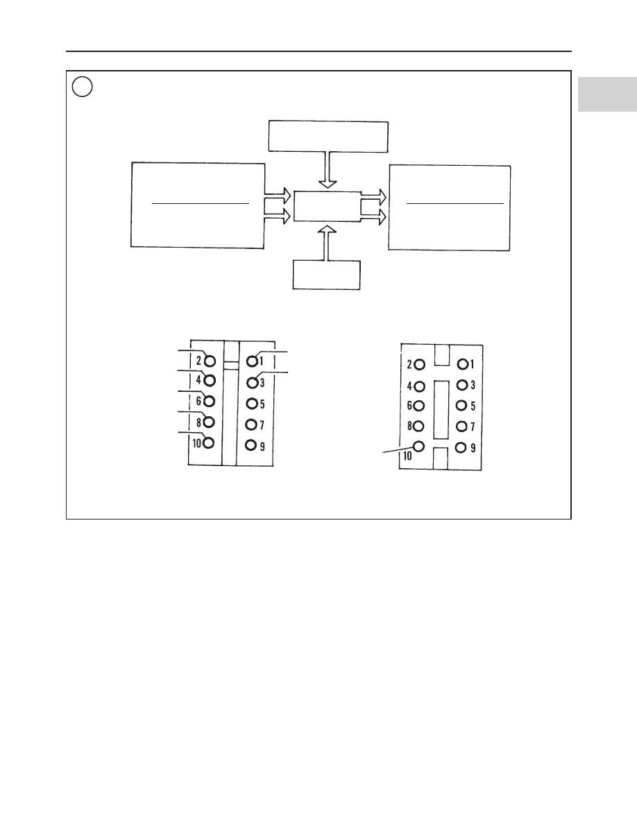
2. After removing the module, identify the socket connec-
tor and module pin connectors using the diagram in Figure
98.
3. With ignition switch off, check for ground at pin No. 1.
4. Turn the ignition switch on.
5. Check for voltage at pin No. 2. Voltmeter should read 12
volts.
6. Connect a jumper wire between pins No. 2 and No. 4.
The right front and rear turn signal lights should illuminate.
TROUBLESHOOTING
101
2
98
TURN SIGNAL MODULE CONNECTORS
(1991-1993 MODELS)
Speedometer
Left turn
signal switch
Right turn
signal switch
Left turn
signal light
Right turn
signal light
Module
Power
Orange
Brown
Violet
White/
brown
White/
violet
Black
White/
green
Socket connector
Pin
Module pin
connector